

Data sheet
Upgradable balancing valves
USV
Application / Description
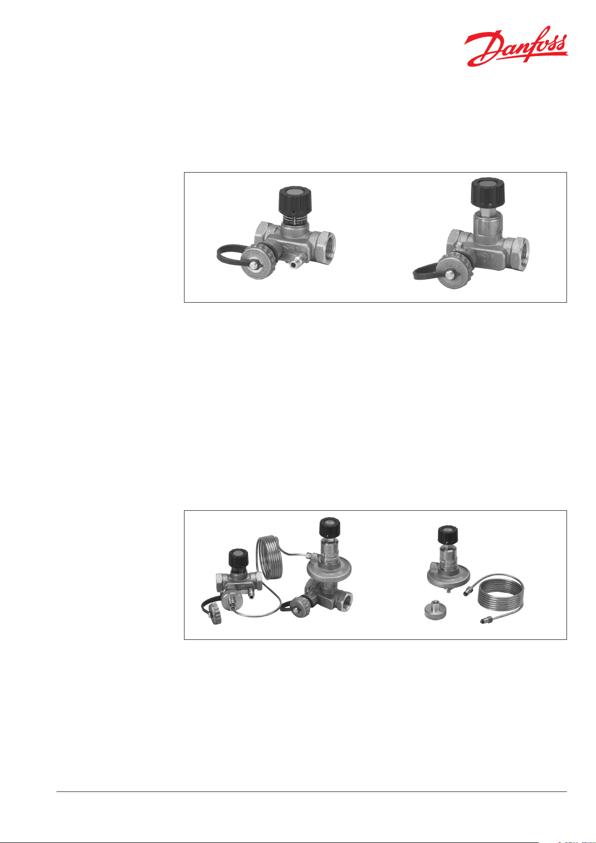
USV-I
USV valves are designed for manual hydronic
balancing of heating and cooling systems.
USV-I (red knob) is used together with USV-M to
limit the flow in heating or cooling installation
or can work separately as manual balancing
valves for flow limitation. If certain pipe sectors
do not require a control of differental pressure,
USV-I and USV-M can be used as shut-off- and
measuring valve.
USV-M (blue knob) valve can be upgraded into
an automatic USV-PV balancing valve. USV-M is
designed for installation in the return pipe.
Upgrading from manual to automatic balancing
is done by mounting PV-controller to an USV-M
valve.
USV-M
System does not need to be depressurized
during the upgrade and the kV-values does not
change. USV-PV maintains constant differential
pressure across a riser.
Due to its special design USV-PV has a firm
connection between diaphragm housing and
valve cone. Diaphragm controller thus acts only
against the force of reference spring. Excelent
control of differential pressure is achieved by the
following design characteristics:
• pressure released cone.
• adapted membrane for every valve
dimension which provides constant quality of
performances for all sizes.
DEN-SMT/SI
USV-PV / I Upgrading of PV-controller from USV-M to USV-PV
USV-PV (blue knob) is designed to maintain
a constant set dierential pressure across a
riser. Eventual operating noise caused by high
dierential pressure induced by changes in the
system can be avoided by upgrading the manual
valve to the dierential pressure controller.
USV-PV can be set to control the dierential
pressure between 0,05 bar to 0,25 bar (5 kPa
to 25 kPa). The PV controller is factory pre-set
to 0,1 bar (10 kPa). PV-controller upgrading
set includes an impulse tube and a threaded
connector for the drain connection of USV-I.
VD.C 1.F3.02 © Danfoss 10/2015
USV-M (PV) and USV-I are compact valves in
which the operating elements and connections
are placed within an arc of 90o, so that in spite
of small valve dimensions, access for installation
and operation is optimal. Insulation caps for
temperature up to 80 oC or 120 oC are available as
accessory.
USV-M and USV-I are supplied in a set-pack with
internal or external thread. If an external thread
is chosen, a threaded or welded plug can be
supplied as an accessory.
1
USV-PV
Data sheet Upgradable balancing valves USV
Application / Description
(continued)
Before upgrading After upgrading
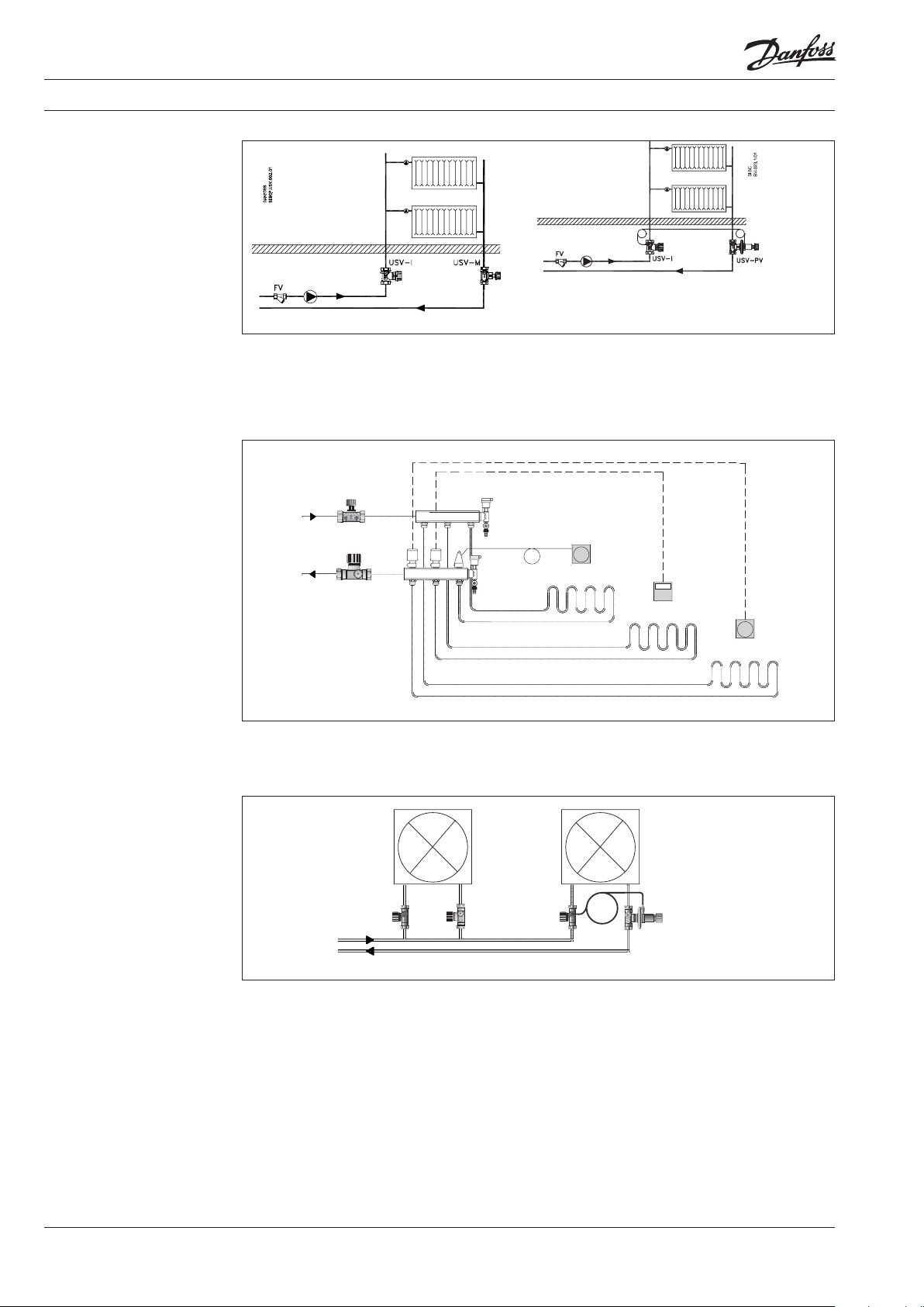
Upgradable USV valves are to be used for
manual as well as automatic balancing of
heating systems. If system has to be fitted with
differential pressure controller, USV can be
upgraded with PV controller.
USV-I
USV-M
TWA
CFD
CFE
CFE
USV in oor heating systems
Upgradable control valves are to be used for
manual balancing of a floor system manifold.
USV-I
USV-M
RA5062
TP5000
RET
USV-I
USV iin cooling systems
Upgradable USV control valves are to be used
for manual or automatic hydronic balancing of
cooling devices i.e. as fan coils or chilled ceilings.
2
VD.C1.F3 .02 © Danfoss 10/2015
DEN-SMT/SI
Data sheet Upgradable balancing valves USV
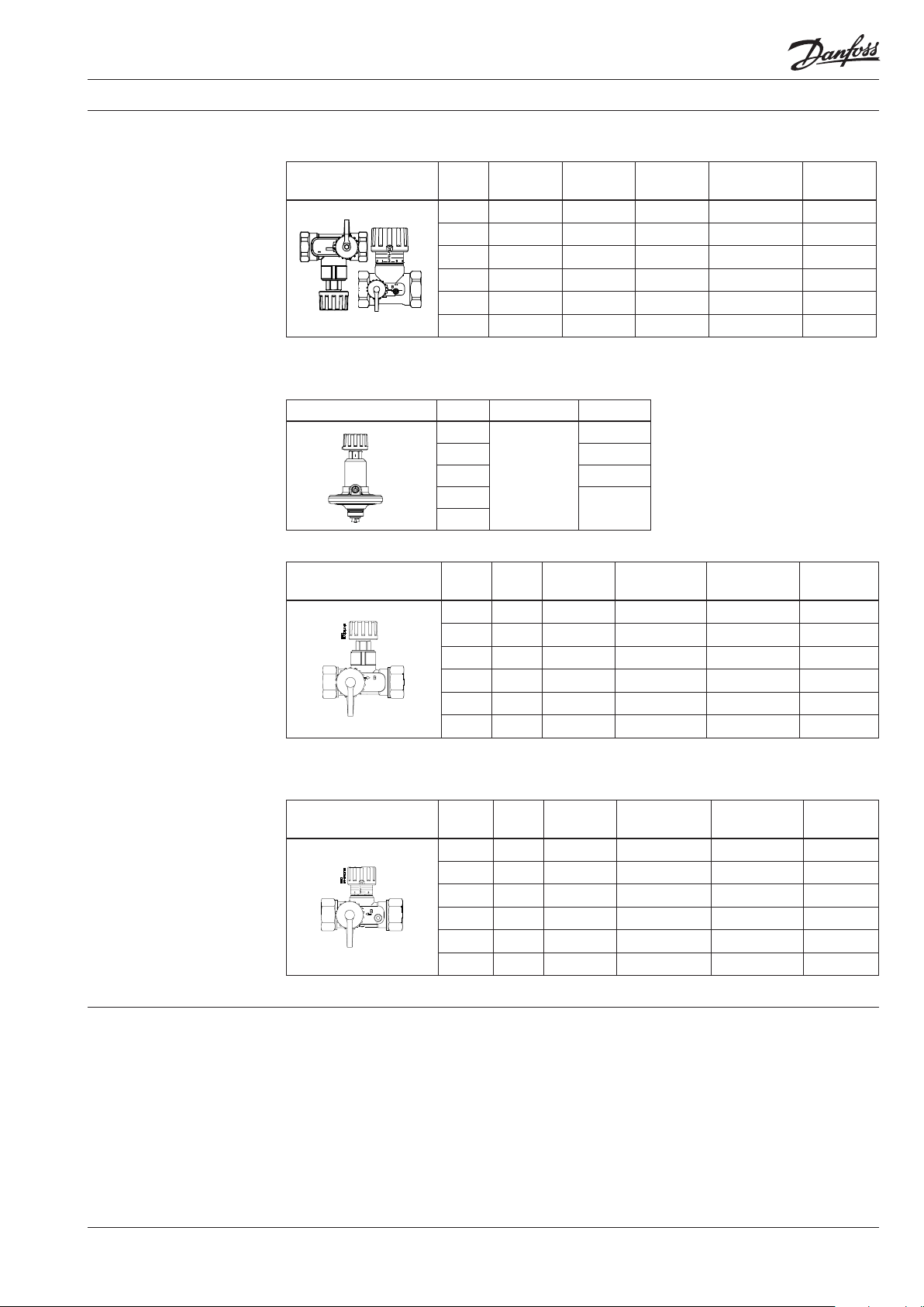
Ordering
USV set-pack (containing one USV-M and one USV-I)
Typ e DN
k
[m3/h]
VS
Int. thread
ISO 7/1
15 1,6 Rp ½
20 2,5 Rp ¾
25 4,0 Rp 1
32 6,3 Rp 1¼
40 10 Rp 1½
50* 16 Rp 2
* DN 50 is not upgrada ble
PV controller for upgrading USV-M valve
Typ e DN Comments Code No.
15 Include:
impulse
20 003Z2157
tube1,5 m
and threaded
25 003 Z2158
connector
32
40
003Z2156
003Z2159
USV-M valve
k
Int. thread
Typ e DN
VS
[m3/h]
ISO 7/1
15 1,6 Rp ½
20 2,5 Rp ¾
25 4,0 Rp 1
32 6,3 Rp 1¼
40 10 Rp 1½
50* 16 Rp 2
* DN 50 is not upgrada ble
Code No.
003Z 2141
003Z 2142
003Z 2143
003Z 2144
003Z 2145
003Z2155
Ext. thread
ISO 228/1
G ¾ A
G 1 A
G 1¼ A
G 1½ A
G 1¾ A
G 2¼ A
It is not neccessary to depressurize
the system in order to upgrade into
dierential pressure controller.
Kv value does not change.
Code No.
003Z2121
003Z 2122
003Z 2123
003Z 2124
003Z 2125
003Z2153
Ext. thread
ISO 228/1
G ¾ A
G 1 A
G 1¼ A
G 1½ A
G 1 ¾ A
G 2¼ A
Code No.
003Z 2146
003Z 2147
003Z 2148
003Z 2149
003Z2150
003Z2160
Code No.
003Z 2126
003Z 2127
003Z 2128
003Z 2129
003Z 2130
003Z2154
Technical data
USV-I valve
k
Int. thread
Typ e DN
VS
[m3/h]
15 1,6 Rp ½
20 2,5 Rp ¾
25 4 Rp 1
32 6,3 Rp 1¼
40 10 Rp 1½
50 16 Rp 2
Max. working pressure ........................................ 16 bar
Test pressure ...........................................................25 bar
Max. dierential pressure across
the valve (USV-M/PV) ....................... 0,8 bar (80 kPa)
Max. dierential pressure across
the valve (USV-I) ............................... 1,5 bar (150 kPa)
Flow temperature ...................... -20 to 120 °C
Ext. thread
ISO 228/1
G ¾ A
G 1 A
G 1¼ A
G 1½ A
G 1 ¾ A
G 2¼ A
ISO 7/1
Code No.
003Z 2131
003Z 2132
003Z 2133
003Z 2134
003Z 2135
003Z2151
Material of parts in contact with water:
Valve body, spindle, etc. ....................................... Brass
Cone (USV-M/PV) ..........................................DZR Brass
Diaphragm and O-rings ...................................... EPDM
Spring ...................................................................Stainless
steel ........................................................................................
Code No.
003Z 2136
003Z 2137
003Z 2138
003Z2139
003Z 2140
003Z2152
DEN-SMT/SI
VD.C1.F3 .02 © Danfoss 10/2015
3
Data sheet Upgradable balancing valves USV
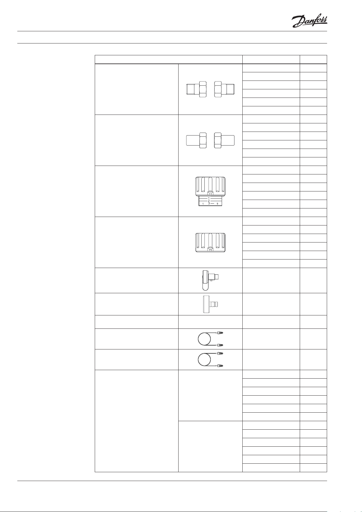
Accessories and spare
parts
Typ e Comments/connection Code No.
Tailpiece threaded
(for external thread only)
Tailpiece welding
(for external thread only)
Shut-o knob for USV-I
(black)
Shut-o knob for USV-M
(black)
DN 15, G ¾ A
DN 20, G 1 A
DN 25, G 1¼ A
DN 32, G 1½ A
DN 40, G 1¾ A 065F6060
DN 50, G 2¼ A 003L8162
DN 15, G ¾ A
DN 20, G 1 A
DN 25, G 1¼ A
DN 32, G 1½ A
DN 40, G 1 ¾ A 065F6080
DN 50, G 2¼ A 003L8163
DN 15 003L 8155
DN 20 003L 8156
DN 25 003L 8157
DN 32 0 03L8158
DN 40 003L8158
DN 50 003L8158
DN 15 003L 8146
DN 20 00 3L8147
DN 25 003L 8148
DN 32 0 03L8149
DN 40 003L 8149
DN 50 003L 8149
003N5070
003N5071
003N5072
003N5073
003N5090
003N5091
003N5092
003N5093
Drain connection 003L 8141
Masuring connector For drain connection 003L8143
Connection plug for impulse tube
(spare part)
Impulse tube 1,5 m 003L8152
Impulse tube 5 m 003L 8153
Insulation cap
up to 80 °C DN 15 003L8165
up to 120 ° C DN 15 00 3L8170
For drain connection 003Z0109
DN 20 003L8166
DN 25 003 L8167
DN 32 003L816 8
DN 40 003L8169
DN 50 003L8164
DN 20 003L8171
DN 25 00 3L817 2
DN 32 0 03L 8173
DN 40 003L 8139
DN 50 003L 8138
4
VD.C1.F3 .02 © Danfoss 10/2015
DEN-SMT/SI

Data sheet Upgradable balancing valves USV
S
E
B
C
P
.A
L
L
E
N
K
E
Y
.
00
1
.0
1
Design
1. Shut-off knob
2. Shut-off spindle
3. Setting spindle
4. Scale disc
5. O-rings
6. Valve cone
7. Valve body
DN
S
S
O
F
N
A
D
15 2,5
20 3
25 4
32 5
40 5
Fig. 8 USV-I
USV-I incorporates a double cone (3,6) able to
give maximum stroke limitation, thus achieving
ow limitation. It also incorporates shut o
function. ASV-I is equipped with the plugs for
the ow measurement and a connection for the
USV-P/PV impulse tube.
Use the following procedure to limit the ow:
turn the valve knob (1) fully counter clockwise to
open the valve. The mark on the knob will now
be opposite »0« on the scale (4). Turn the valve
knob (1) clockwise to the required setting (e.g.
for setting 2,2 the knob must be rotated two full
turns and then forward to »2« on the scale. Hold
USV-M
Port A Port B
the knob (1) to keep the setting (e.g. 2,2) and
using a hexagon socket key turn the spindle (3)
fully counter clockwise (until a stop can be felt).
Turn the valve knob (1) fully counter clockwise
so that the mark on the knob is opposite »0«
on the scale (4). The valve is now open as many
turns from the closed position (2,2) as indicated
by the convertion from required ow. To annul
the setting, turn the hexagon socket key fully
clockwise (until a stop can be felt).
Remember, at the same time the knob must be
held on its »0« setting.
DEN-SMT/SI
DN 15 - 40 DN 50
USV-M can be upgraded to USV-PV automatic
USV-M dimension DN 50 is not upgradable.
balancing valve. The system does not need to be
depressurized during the upgrade.
VD.C1.F3 .02 © Danfoss 10/2015
5

Data sheet Upgradable balancing valves USV
S
E
B
C
P
.A
L
L
E
N
K
E
Y
.
00
1
.0
1
Design (continued)
1. Shut-off knob
2. Differential pressure setting
spindle
3. O-ring
4. Reference spring
5. Impulse tube connection
6. Diaphragm element
7. Control diaphragm
8. Pressure-relieved valve cone
9. Valve body
USV-PV valve
DN
15
20
25
32
40
2,5
Tur ns
(n)
S
S
O
F
N
A
D
0 0,25
bar
1 0,24
3
4
5
5
2 0,23
3 0,22
4 0, 21
5 0,2
6 0,19
7 0 ,18
8 0,17
9 0 ,16
10 0,15
11 0 ,14
12 0,13
13 0,12
14 0 ,11
15 * 0,1
16 0,09
17 0,08
18 0,07
19 0,06
20 0,05
* Factory se tting
USV-PV is designed to maintain a constant set
dierential pressure. Via an internal connection
- trough the cone (8) and together with the
reference spring (4), pressure in the return pipe
acts on the underside of the control diaphragm
(7) while via an impulse tube (5), pressure in the
ow pipe acts on the top of the diaphragm. In
this way the balancing valve maintains adjusted
dierential pressure in the riser.
USV-PV is factory-set on 0,1 bar (10 kPa). The
dierential pressure can be varied between
0,05bar and 0,25 bar (5 kPa and
25 kPa).
6
VD.C1.F3 .02 © Danfoss 10/2015
DEN-SMT/SI

Data sheet Upgradable balancing valves USV
Sizing Required:
A. Correct valve size USV-M / I
B. Correct USV-I presetting
Given:
1. Required max. flow in the riser
Q = 0,80 [m3/h]
2. Pressure drop across riser
Δps = 15 [kPa]
3. Available pump pressure
Δpo = 45 [kPa]
Solution:
A) Correct valve size :
Pipe size and low pressure drop (fully opened
valve) can be criterions for valve selection.
The example selects USV-M 20 valve. Pressure
drop is read from sizing diagram (page 8) by
taking a horizontal line from DN 20 valve with
presetting 3,2 (fully opened valve) to intersect
kV-axis at 2,5 [m3/h].
Δpo = Δpv(USV-I) + Δps + Δpv (USV-M)
B) Correct valve size and presetting of USV-I:
The differential pressure across USV-I can be
calculated as follows:
Δpv (USV-I) = Δpo – Δps – Δpv(USV-M)
Δpv = 45 [kPa] – 15 [kPa] – 10 [kPa] = 20 [kPa]
The example selects USV-I 20. Presetting is
read from the sizing diagram (page 7) by
taking a straight line from from max. flow
Q = 0,80 [m3/h] to the differential pressure Δpv
(USV-I)= 20 [kPa] and to the intersection with
kV-axis at kV = 1,8 [m3/h].
A straight line conecting this point and
Q = 0,80 [m3/h] intersects the differential
pressure bar at Dpv (USV-M) = 10 [kPa].
Draw a horizontal line from this point to the
adjustment curve of the chosen valve
(DN 20). Starting from closed valve, the
presetting of 1,6 turns is required.
USV-PV
Required:
Diff. pressure setting of USV-PV
Given:
1. Required max. flow in the riser
Q = 0,80 [m3/h]
2. Pressure drop across riser
3. Δps = 15 [kPa]
4. Available pump pressure
Δpo = 45 [kPa]
Solution:
Δpa = Δpv (USV-I) - Δpo - Δpv (USV-PV)
USV-M is upgraded to USV-PV by mounting the
PV controler to the USV-M valve and connecting
it to the USV-I by the means of impulse tube.
USV-PV maintains constant differential pressure
Δpa (pressure drop across riser - see fig.). USV-PV
is to be set at Δpa = 15 [kPa].
kV-values [m3/h] for various presettings:
Size
0,20 0,60 1,00 1,40 1,80 2,20 2,70 3,20
Number of turns
DN 15 0,2 0,5 0,8 1,1 1,2 1,4 1,6 1,6
DN 20 0,3 0,8 1,3 1,6 1,9 2,1 2,4 2,5
DN 25 0,4 1,3 1,9 2,6 3 ,1 3,4 3,7 4,0
DN 32 0,7 2,0 3,1 4,1 4,9 5,4 5,9 6,3
DN 40 1,1 3,1 4,9 6,4 7,6 8,5 9,1 10,0
DN 50 1,7 4,9 7,6 10,0 11,9 13, 3 14,4 16,0
DEN-SMT/SI
VD.C1.F3 .02 © Danfoss 10/2015
7

Data sheet Upgradable balancing valves USV
Q x1 0
Sizing (continued)
A straight line connecting the bars of flow,
differential pressure and kV value shows the
relationship between these three variables.
k
=
v
p
Δ
A horizontal line from the intersection with the
kV bar shows the presetting value for each valve
size.
Q [m3/h]
Δp [kPa]
8
VD.C1.F3 .02 © Danfoss 10/2015
DEN-SMT/SI

Data sheet Upgradable balancing valves USV
Measurement of flow and
differential pressure
Installation
Pressure testing
USV-I is tted with a test plug and a drain
connection and the pressure drop across valve
can be measured with Danfoss measuring device
PFM 3000 or other standard devices.
Using the pressure drop characteristics of USV-I
and dierential pressure of the fully opened
valve, actual ow can be obtained.
USV-I must be instaled in the ow pipe.
USV-M must be installed in the returned pipe.The
direction of the ow must follow the direction of
the arrow on the valve body.
USV-M and USV-I can be installed in any
positions if installation instructions are being
observed. t is recommended that a lter i.e.
Danfoss Typ FV is installed in the supply pipe.
After upgrading USV-M to USV-PV the impulse
tube between USV-I and USV-PV must be ushed
through before installation.
Max. test pressure ............................................... 25 bar
When pressure testing the system you must
secure that both sides of the membrane have the
same static pressure to prevent damage of the
pressure controller. That means the impulse tube
must be connected and any needle valves must
be open.
Note:
When measuring the pre-set ow all radiator
valves must be set for the nominal ow.
Dierential pressure [Δpr ] measuring in the
riserdes.
Drain connection of the USV-I and USV-M is to be
tted wit a measuring connector (Danfoss Code
No. 003L8143) .
A 90° angle between service features (shut-o
on the one side, measuring and draining on the
other), allow upside down installation and easy
measuring, shut-o and draining of the system.
If USV-PV is installed in combination with USV-I,
both valves can be open or closed (both valves
must be in the same position!).
DEN-SMT/SI
VD.C1.F3 .02 © Danfoss 10/2015
9

Data sheet Upgradable balancing valves USV
Dimensions
Ext. thread Int. thread
With tailpiece welding With tailpiece threaded
L
L
L
1
Typ e
[mm]
[mm]
2
[mm]
US V-I 15 65 131 139 48 15 28 27 Rp ½ G ¾ A 0, 31
USV-I 20 75 147 159 60 18 35 32 Rp ¾ G 1 A 0,4
USV-I 25 85 169 169 75 23 45 41 Rp 1 G 1¼ A 0,67
USV-I 32 95 191 179 95 29 55 50 Rp 1¼ G 1½ A 1,1
USV-I 40 10 0 202 18 4 100 31 55 55 Rp 1½ G 1¾ A 1,22
USV-I 50 130 246 214 106 38 55 67 Rp 2 G 2¼ A 2
H
3
[mm]
H
1
[mm]
D
2
1
[mm]S[mm]aIS O 7/1bISO 228/1
Weight
[kg]
Ext. thread Int. thread
With tailpiece welding With tailpiece threaded
L
L
L
H
H
Typ e
[mm]
1
2
3
[mm]
[mm]
[mm]
1
D
2
[mm]
1
[mm]S[mm]aIS O 7/1bISO 228/1
US V-M 15 65 131 139 61 15 28 27 Rp ½ G ¾ A 0,28
USV-M 20 75 147 159 76 18 35 32 Rp ¾ G 1 A 0,4
USV-M 25 85 169 169 96 23 45 41 Rp 1 G 1¼ A 0,73
USV-M 32 95 191 179 121 29 55 50 Rp 1¼ G 1½ A 1,28
USV-M 40 100 202 184 126 31 55 55 Rp 1½ G 1¾ A 1,35
USV-M 50 130 246 214 106 38 55 67 Rp 2 G 2¼ A 2
Weight
[kg]
10
VD.C1.F3 .02 © Danfoss 10/2015
DEN-SMT/SI

Data sheet Upgradable balancing valves USV
Dimensions (continued)
L
L
L
1
Typ e
[mm]
[mm]
2
US V-PV 15 65 131 139 115 15 28 61 27 Rp ½ G ¾ A 0,55
USV-PV 20 75 147 159 14 4 18 35 76 32 Rp ¾ G 1 A 0,9
USV-PV 25 85 169 169 184 23 45 98 41 Rp 1 G 1¼ A 1,8
USV-PV 32 95 191 179 230 29 55 122 50 R p 1¼ G 1½ A 3,35
USV-PV 40 100 202 184 235 31 55 122 55 Rp 1½ G 1¾ A 3,45
3
[mm]
H
[mm]
1
H
[mm]
D
2
D
1
[mm]
2
mmS[mm]aIS O 7/1bISO 228/1
Weight
[kg]
DEN-SMT/SI
VD.C1.F3 .02 © Danfoss 10/2015
h
[mm]
DN 15 150
DN 20 200
DN 25 250
DN 32/4 0 320
min
11

Data sheet Upgradable balancing valves USV
12
VD.C1.F3 .02
Produce d by Danfoss A/S © 10/2015
 Loading...