

Page 1
Data sheet
UnoFloor Mixing
General description
and application
Ordering
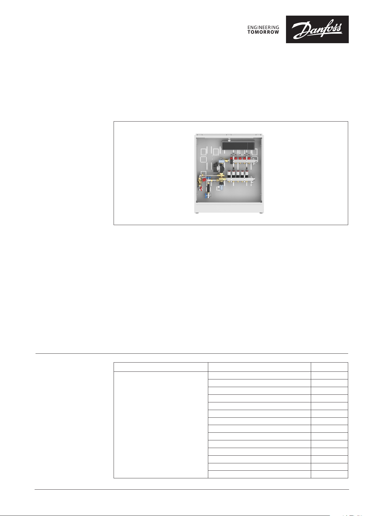
The Danfoss UnoFloor Mixing is a preassembled
pressure independent underfloor heating
balancing and control distribution unit. UnoFloor
comes wired and premounted. UnoFloor Mixing
includes Danfoss Icon™ 230V Wiring Center or
Danfoss Icon™ 24V Master Controller.
The SSM stainless-steel manifold is used for
controlling water flow. Each tube of the floor
heating system is connected to the manifold,
thus making it possible to control water flow
or heat supply to each room in the building
individually.
The AB-PM set ensures optimal hydronic balance.
Flow limitation independent of differential
pressure is now guaranteed.
The Danfoss compact mixing shunt is used for
regulation of flow and supply temperature in
hydronic floor heating systems.
Description Typ e Code no.
Pressure independent underfloor
heating balancing and control
distribution unit includes:
• Danfoss Icon 230V Wiring Center
or Danfoss Icon™ 24V
Master Controller.
• Actuators
• Stainless steel manifold
• AB-PM set
• FHM-C1 Mixing shunt
• Cabinet
• Nominal pressure PN 6
• Max. Temperature 90 °C
• G ¾” internal thread
Use heating water according VDI 2035
or ONORM H 5195.
Unofloor Mixing 4 Loops Left Icon 230V 088X4604
Unofloor Mixing 5 Loops Left Icon 230V 088X4605
Unofloor Mixing 6 Loops Left Icon 230V 088X4606
Unofloor Mixing 7 Loops Left Icon 230V 088X4607
Unofloor Mixing 8 Loops Left Icon 230V 088X4608
Unofloor Mixing 10 Loops Left Icon 230V 088X4610
Unofloor Mixing 12 Loops Left Icon 230V 088X4612
Unofloor Mixing 4 Loops Right Icon 230V 088X4624
Unofloor Mixing 5 Loops Right Icon 230V 088X4625
Unofloor Mixing 6 Loops Right Icon 230V 088X4626
Unofloor Mixing 7 Loops Right Icon 230V 088X4627
Unofloor Mixing 8 Loops Right Icon 230V 088X4628
Unofloor Mixing 10 Loops Right Icon 230V 088X4630
Unofloor Mixing 12 Loops Right Icon 230V 088X4632
Features:
• Compact design - fits in even
the smallest places
• In-wall cabinet ensures flush installation
• Pre-mounted - minimal risk
of installation faults
• Easy ordering - only one number necessary
• Short installation time
• Correct heat distribution, even
under partial load
• Reliable hydronic balancing
for lower heating costs
• Energy-saving
• Pressure-independent AB-PM valve integrated
• Integrated mixing shunt with safety
thermostat and self-acting thermostatic sensor
© Danfoss | 2022.03
AI405949559758en-010201 | 1
Page 2
Data sheet UnoFloor Mixing
Accessories
SSM
Floor Heating Manifold
Description Code no.
Danfoss Icon™ Dial,
In-wall
Danfoss Icon™
Display, In-wall
Danfoss Icon™
Programmable,
In-wall
Floor sensor 088U1110
088U1000
088U1010
088U1020
Description Code no.
Danfoss Icon™ Dial,
On-wall
Danfoss Icon™
Display, On-wall
Danfoss Icon™
Programmable,
On-wall
The SSM manifold is used for controlling water
flow in under floor heating systems. Each tube of
the floor heating system is connected to the
manifold, thus making it possible to control water
flow or heat supply to each room in the building
individually.
088U1005
088U1015
088U1025
Part of assembly
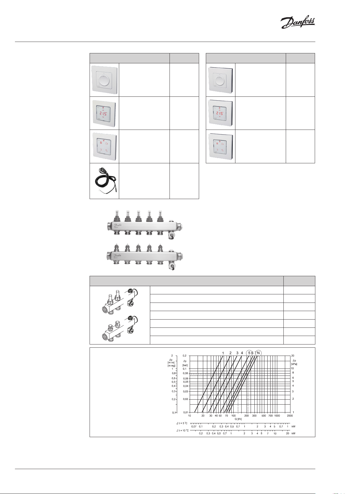
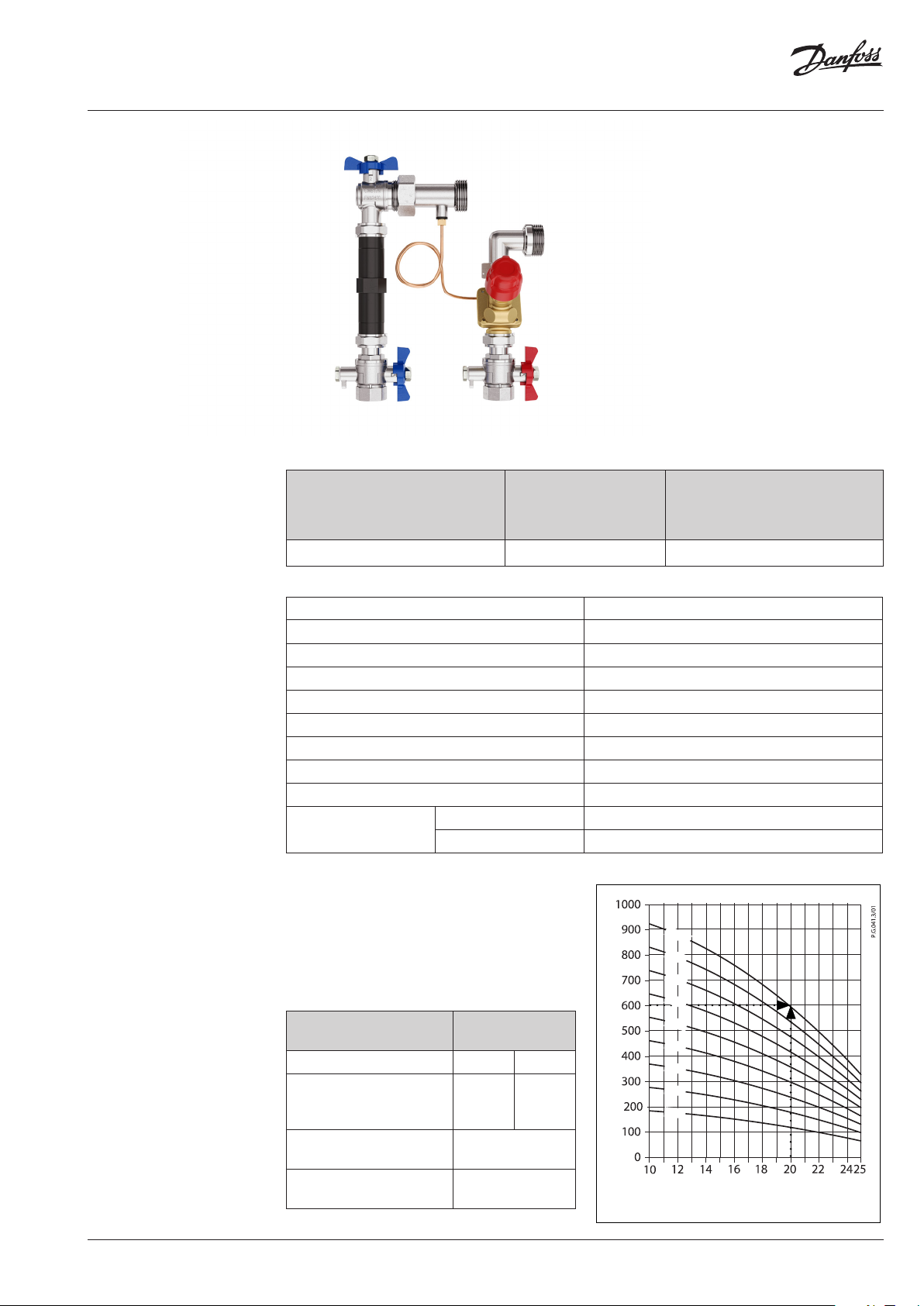
Pre-setting diagram
Presetting the manifold
valves
Description Type
Manifold set 4+4, with flowmeter SSM-4F
Manifold set 5+5, with flowmeter SSM-5F
Manifold set 6+6, with flowmeter SSM-6F
Manifold set 7+7, with flowmeter SSM-7F
Manifold set 8+8, with flowmeter SSM-8F
Manifold set 10+10, with flowmeter SSM-10F
Manifold set 12+12, with flowmeter SSM-12F
Manifold,
with flowmeter
The diagram shows the capacities for each
heating circuit at different presettings of the
manifold valves.
Based on the above calculations and capacity diagram each manifold valve is preset by rotating
the red ring until the correct value on the ring is
in-line with the sight mark on the valve.
2 | © Danfoss | 2022.03
AI405949559758en-010201
Page 3
Data sheet UnoFloor Mixing
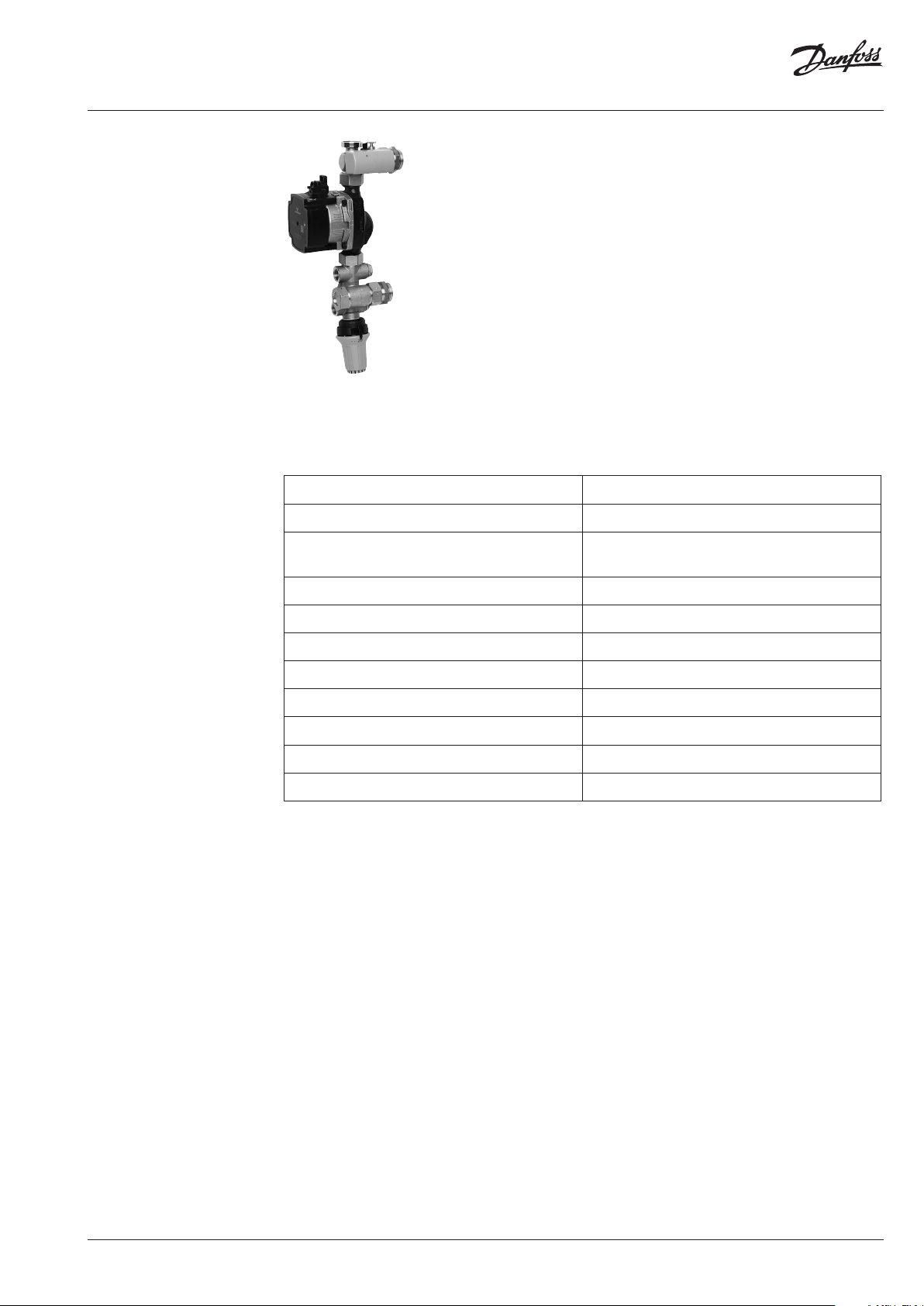
FHM-C1 Mixing shunt
Mixing shunt
FHM-C1
Technical specifications
Supply voltage 230 V AC
Primary connection ½” (DN15)
Max. differential pressure with Danfoss Floor
Heating manifolds
Max. working pressure PN10
Max. flow temperature 90 °C
FTC flow temperature control 18 °C to 50 °C
FH-DT supply flow thermometer 0 °C to 60 °C
Integrated check valve POM / Stainless steel
Body, unions and other metal parts Brass / Stainless steel
O-rings and seals EPDM
Weight approx. 3,5 kg to 4 kg (depending on model)
0,6 bar
AI405949559758en-010201
© Danfoss | 2022.03 | 3
Page 4
Data sheet UnoFloor Mixing
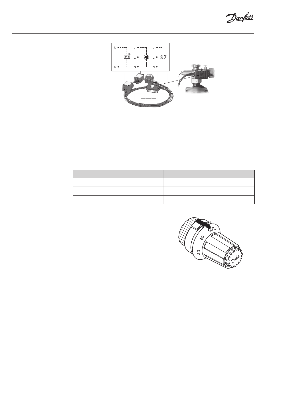
FH-ST55
Safety thermostat
230V / 16A
55°C
T
S
Electrical connection
FTC
Temperature controller
The FH-ST safety thermostat is fixed on the tube
and protects floor and system against too high
temperatures, especially important for wooden
floors. The FH-ST thermostat switches off the pow-
automatically and the floor heating system is protected.
The FH-ST55 can also be connected to a pump or
a zone valve.
er supply of the floor heating base unit, when the
temperature reaches 55 °C.
By switching off the power supply of the floor
Note! The electrical installation must be carried out
by an authorized installer only (230 V DC).
heating base unit, the actuators (NC) will close
Code no. 088U0301
Shut-off temperature 55 °C
Switch difference 4 K
Classification IP 40 (mounted)
FTC is a self-acting thermostatic sensor used for
flow temperature control of floor heating.
The water temperature is measured by a surface
sensor. The snap-lock connector of the sensor element secures a firm connection to the valve.
Features:
• Closes on rising sensor temperature.
• Temperature range: 15 °C to 50 °C
4 | © Danfoss | 2022.03
AI405949559758en-010201
Page 5
Data sheet UnoFloor Mixing
AB-PM DN20 HP set
vertical
Part of assembly
The AB-PM connection set is an compact and time
saving configuration — designed for creating optimal hydronic balance in horizontal loops — radiator and underfloor heating applications. Flow limitation independent of differential pressure is now
guaranteed. It can be combined with most types
of manifolds, heat meters and manifold cabinets.
One packing unit contains the following products:
• AB-PM valve;
• Impulse tube, 1,5 m, R 1/16;
•
Adapter R 1/16 for AB-PM impulse tube connection;
•
3-piece ball valve with connection for impulse
tube heat meter;
• Adapter for heat meter;
•
Connector/bracket for underfloor heating distributor G 1 A.
External thread
connection to underfloor
heating distributor
(ISO 228/1)
Typ e
External thread
AB-PM
(ISO 228/1)
AB-PM DN20 HP set vertical G 1 A G 1 A
Technical data
Nominal diameter DN 20 HP
Qmax (at ∆pr = 20 kPa) 600 l/h (at 100 % setting)
Upper limit of pressure controller at zero flow 35 kPa
Differential pressure (p for the valve + circuit) 28–400 kPa
Nominal maximal pressure 16 bar (PN 16)
Control valves characteristic Linear
Shut-off leakage rate Acc. to ISO 5208 class A — no visible leakage
Medium temperature −10 °C to +120 °C
CV stroke 2,25 mm
Connection Ext. thread ISO 228/1 G 1 A
Actuator M 30 × 1,5
Sizing AB-PM is to be sized based on manifold’s needed
flow (Q) [l/h], and needed differential pressure
drop for the loop (∆pr). Manifold pre-setting data
are presented on page 4. Max AB-PM flow data are
presented in table 1.
For any other Q and ∆pr needed, AB-PM size and
setting can be indetified based on Fig. 1.
Typ e
DN 20 HP at
100% setting
Q max. 600 l/h 915 l/ h
Maximum pressure drop
available for system at
20 kPa 10 kPa
max flow
Upper limit of pressure
controller at zero flow
Start required differential
pressure (for the valve)
35 kPa
8 kPa
DN 20 HP
100 %
90 %
80 %
70 %
60 %
50 %
40 %
30 %
20 %
flow [l/h]
∆pr [kPa]
Fig. 1
AI405949559758en-010201
© Danfoss | 2022.03 | 5
Page 6

Data sheet UnoFloor Mixing
TWA
Thermal Wax Actuator
Part of assembly
Technical specifications
The TWA is a small actuator for electrical on/off
controls to activate several types of valves and
floor heating manifolds.
Actuator Connection type Supply Voltage
TWA-A RA 230 V AC or 24 V AC/DC
Supply voltage 230 V (3 A pre-fuse) or 24 V (Class II (SELV))
Max. inrush current 230 V: 250 mA or 24 V: 250 mA
Frequency 50- 60 Hz
Running power consumption 2 W
Spindle travel time ~3 min.
Ambient temperature 0 °C to 60 ° C
Enclosure IP 41
Cable length 950 m m
kvs (m³/H) 0,10 to 1,10
Max. ∆p (Bar) 0,6
Danfoss Icon 230V
Wiring Center
Danfoss Icon™ 230V Wiring Center is a connection
box for use in hydronic floor heating using 230V
thermostats and actuators.
The Icon™ 230V Wiring Center can connect up
to 14 thermal actuators from up to 8 room thermostats. It is provided with 230V Live circulation
pump output and a voltage-free relays for controlling a boiler. The relays are activated when one or
more thermostats require heat.
The Wiring Center also supports away and cooling
mode which can be controlled by a 230 V signal as
well as LED’s to indicate when outputs are active.
Mounting is made easy due to a simple layout of
the terminals and clear marking on the screw terminals. Mounting can be done by using screws.
6 | © Danfoss | 2022.03
AI405949559758en-010201
Page 7
Data sheet UnoFloor Mixing
Technical data
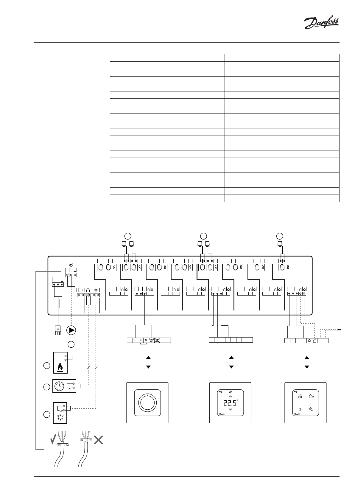
Wiring
Max. number of thermostats 8
Max number of actuators 14
Supported actuator types Normally closed (NC)
Internal fuse 3 A
Conforms with diectives LVD, EMC, RoHs, WEEE
Supply voltage 220-240 V AC
Supply frequency 50/60 Hz
Output voltage, actuators 230 V AC
Ambient temp. range, operation 0 °C to 50 °C
Storage temp. range −20 °C to +60 °C
Output relay, pump 230 V Max. 100 W
Output relay, boiler Voltage-free Max. 2 A
Output cooling 230 V when active
Output Setback 230 V when active
Input Cooling External switch input (230 V rating)
Input setback External switch input (230 V rating)
Rated impulse voltage 4 kV
Temperature for ball pressure test 75 °C
Control pollution degree Pollution degree 2
Disposal instructions As electronic waste
Icon™ 230V Wiring Center
MAX. 100 W
L N
L N
3A
Mains
Option
220 -240 VAC
Option
2
Option
3
50/60 Hz
HE AT!
1
2× ≤ 1,5 mm
5 5 5
1 1 2 2 3 3 4 4 5 5 6 6 7 8
THE RMO STAT 1 THE RMOS TAT 2 THE RMOS TAT 3 THER MOS TAT 4 THER MOST AT 5 THER MOSTAT 6 THER MOSTAT 7 THERM OSTAT 8
SWITCH
EXTERNAL
L N
2× ≤ 1,5 mm
L N
LOAD
≤ 1,5 mm ≤ 1,5 mm ≤ 1,5 mm
L N
LOAD
L N
LOAD
L N
LOAD
L NN
L N
LOAD
Load
L
L N
LOAD
L N
LOAD
L N N NTC
Example: Icon™ ProgrammableExample: Icon™ DisplayExample: Icon™ Dial
LOAD
Options
Option
Load
L
Sensor
Option
4
AI405949559758en-010201
© Danfoss | 2022.03 | 7
Page 8

Data sheet UnoFloor Mixing
Danfoss Icon™
Master Controller 24V
Technical data
Master Controller 24V and
Expansion Module (optional)
Danfoss Icon™ is a modular heating system for
individual room control. It can be configured as
a wired or wireless system or as a combination, if
required.
For all applications please see Installation guide for Expansion Module.
Supply voltage 220-240 V AC
Supply frequency 50/60 Hz
Output voltage, actuators 24 V DC
Max. power consumption per actuator output 2 W
Number of actuator outputs
(1 actuator per output terminal)
Output voltage, thermostats 24 V DC
Max. number of thermostats 10
Dimensions W: 370 mm, H: 100 mm, D: 53 mm
Encapsulation (IP Class) IP 20
The center of the system is the Danfoss Icon™
Master Controller 24 V, which configures and ties
the system together.
Installation and set-up of the Danfoss Icon™
Master Controller 24 V is made easy by using the
pre-defined application and intuitive touch user
interface.
10
8 | © Danfoss | 2022.03
AI405949559758en-010201
Page 9

Data sheet UnoFloor Mixing
Dimensions
C
B
110
B
A
number of
circuits
A B C
4, 5, 6 753 mm 790 mm 939 mm
7, 8 864 mm 940 mm 939 mm
10, 12 1057 mm 114 0 mm 939 mm
159
AI405949559758en-010201
© Danfoss | 2022.03 | 9
Page 10

Data sheet UnoFloor Mixing
Tender text
Pre-assembled underfloor heating balancing and
control distribution unit must come wired and
pre-mounted, suitable for left- and right-hand
side connection to the manifold, fitted in in-wall
cabinet. Cabinet must be painted in white (RAL
9016), 939 mm in height, up to 1140 in width and
110 in depth.
The manifold is used for heat regulation in floor
heating systems. Each circuit in the floor heating
system is connected to the manifold, which
makes it possible to regulate the heat supply to
each room in the building independently.
The manifold shall consist of a flow and return
manifold where the flow manifold must be able
to close each circuit independently. The return
manifold must be equipped with presetting
valves, ensuring optimal balancing of the system.
Balancing of the floor heating system shall be
done on a swivel scale ranging from 1-7 and
N so that the value can be read and checked
after commissioning. Valves shall be controlled
electronically by thermal actuators installed
without adapters.
The manifold must be provided in modules of up
to 12 outlets with air vent and drain / fill function
valve. Ball valves must be available as an option
for positive shut-off between manifold and
system.
The manifold must be made of stainless steel
and have the following specifications:
• Maximum flow temperature : 90 °C
• Maximum differential pressure: 0,6 bar
• Maximum operating pressure with
flow meter: 6 bar
• Max Kv setting of the valve (N): 0,97 m
The mixing shunt shall be compact, has a flexible
design, which allows mounting directly to the
manifold on both left and right side. Primary
pipe connection must be from the side or below.
Mixing shunt must have a possibility to
regulate the supply temperature by self-acting
proportional regulator. The regulator ensures
that the desired supply temperature to the
floor heating system always remains constant
and can be set from 15°C to 50°C. Mixing shunt
must be equipped with a built-in check valve,
which ensures correct flow direction. An air-vent
on top and a thermometer shall complete the
mixing shunt. Mixing shunt must be equipped
with a low-energy, variable speed pump 130mm
mounting length.
The mixing shunt must be made of brass and
stainless-steel components and have the
following specifications:
• Supply voltage: 230V
• Primary connection: G ½ “
• Manifold connection: G 1”
• Maximum flow temperature: 90°C
• Flow temperature control: 15°C to 50°C
• Maximum different pressure: 0.6 bar
• Maximum working pressure: 10 bar
• Pump type: low-energy, variable speed,
130mm mounting length
• Weight: 3.5 - 4 kg
Icon 230V wiring center:
It must be possible to connect the room
thermostats to the NC actuators via a connection
box.
The connection box must have not less
8 channels and 14 actuator outputs, have two
potential free relays: one for the pump and one
for the boiler. Distribution voltage: 230 V AC.
Voltage: 230 V AC, max. power per output: 3 W.
The actuator must be premounted on a valve.
The actuator receives a signal from the room
thermostat. Based on the signal, it opens and
closes the valve which makes it possible to
regulate the energy supply to each room in the
building independently. For easy and secure
installation, the actuator must be delivered
as one part (no adapter) and mounted on the
manifold by use of an Allen screw.
Icon 24V master controller:
It must be possible to connect the room
thermostats to the NC/NO actuators via
a connection box.
The connection box must have not less
10 channels and 10 actuator outputs, have
potential-free relay, one micro disconnection
output and permanent 230 V (max 50W) output.
Supply voltage: 230 V AC. Output voltage for
actuators: 24 V DC, max. power per output: 2 W.
It must be possible to set up to 10 actuators for
1 room thermostat. It must be possible to control
system by smartphone app and have pre-set
work profiles with applications. Connection box
must have possibility to be upgraded to wireless
solution by Wireless module. For accurate
hydronic control, automatic heat load control
feature must be available.
The actuator must be premounted on a valve.
The actuator receives a signal from the room
thermostat. Based on the signal, it opens and
closes the valve which makes it possible to
regulate the energy supply to each room in the
building independently. For easy and secure
installation, the actuator must be delivered
as one part (no adapter) and mounted on the
manifold by use of an Allen screw.
10 | © Danfoss | 2022.03
AI405949559758en-010201
Page 11
Data sheet UnoFloor Mixing
Spare parts
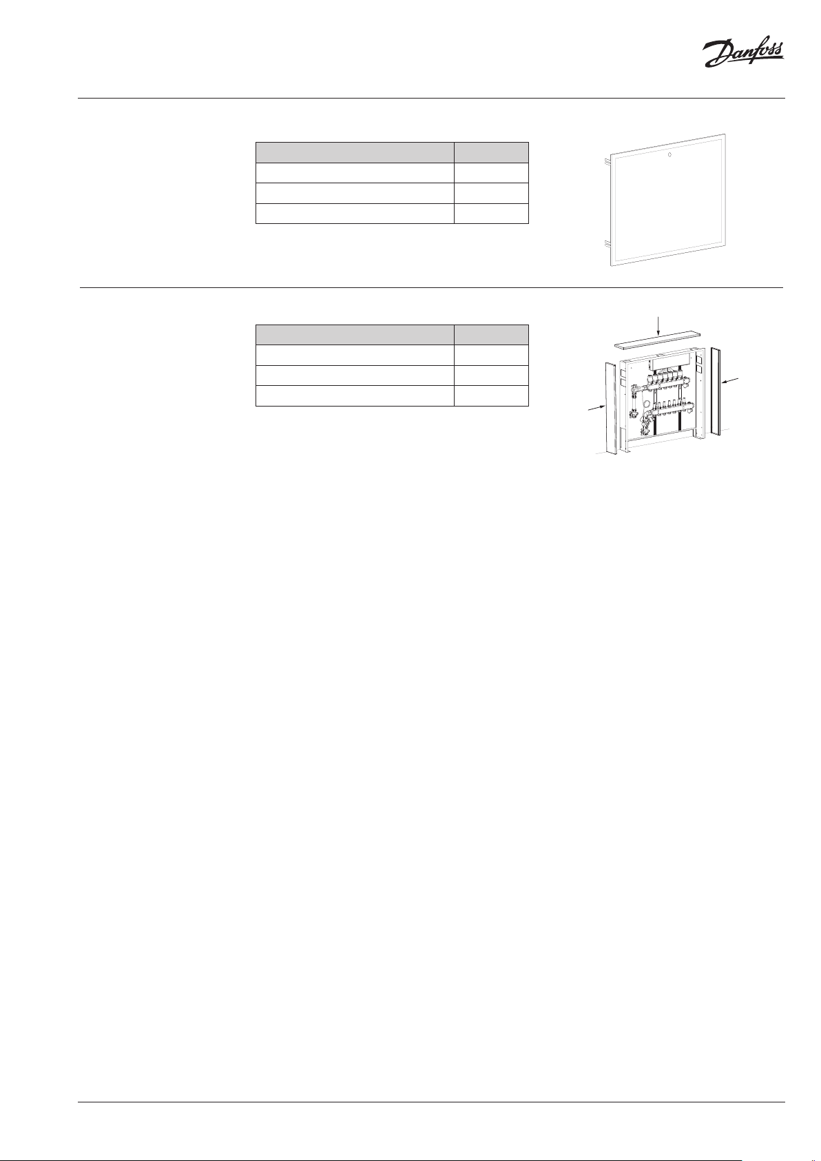
Accessories
Frame and door for service are available on demand.
Description Code no.
Frame and door for cabinet 790 088X3020
Frame and door for cabinet 940 088X3022
Frame and door for cabinet 1140 088X3024
Panels for wall mounting are available on demand.
Description Code no.
On wall panels for cabinet 790 088X3026
On wall panels for cabinet 940 088X3028
On wall panels for cabinet 1140 088X3030
AI405949559758en-010201
© Danfoss | 2022.03 | 11
Page 12

Data sheet UnoFloor Mixing
12 | © Danfoss | DCS-SGDPT/PL | 2022.03
AI405949559758en-010201
 Loading...