

Data sheet
UnoFloor Light, Light C and Light Ci
General description
and application
© Danfoss | 2021.12
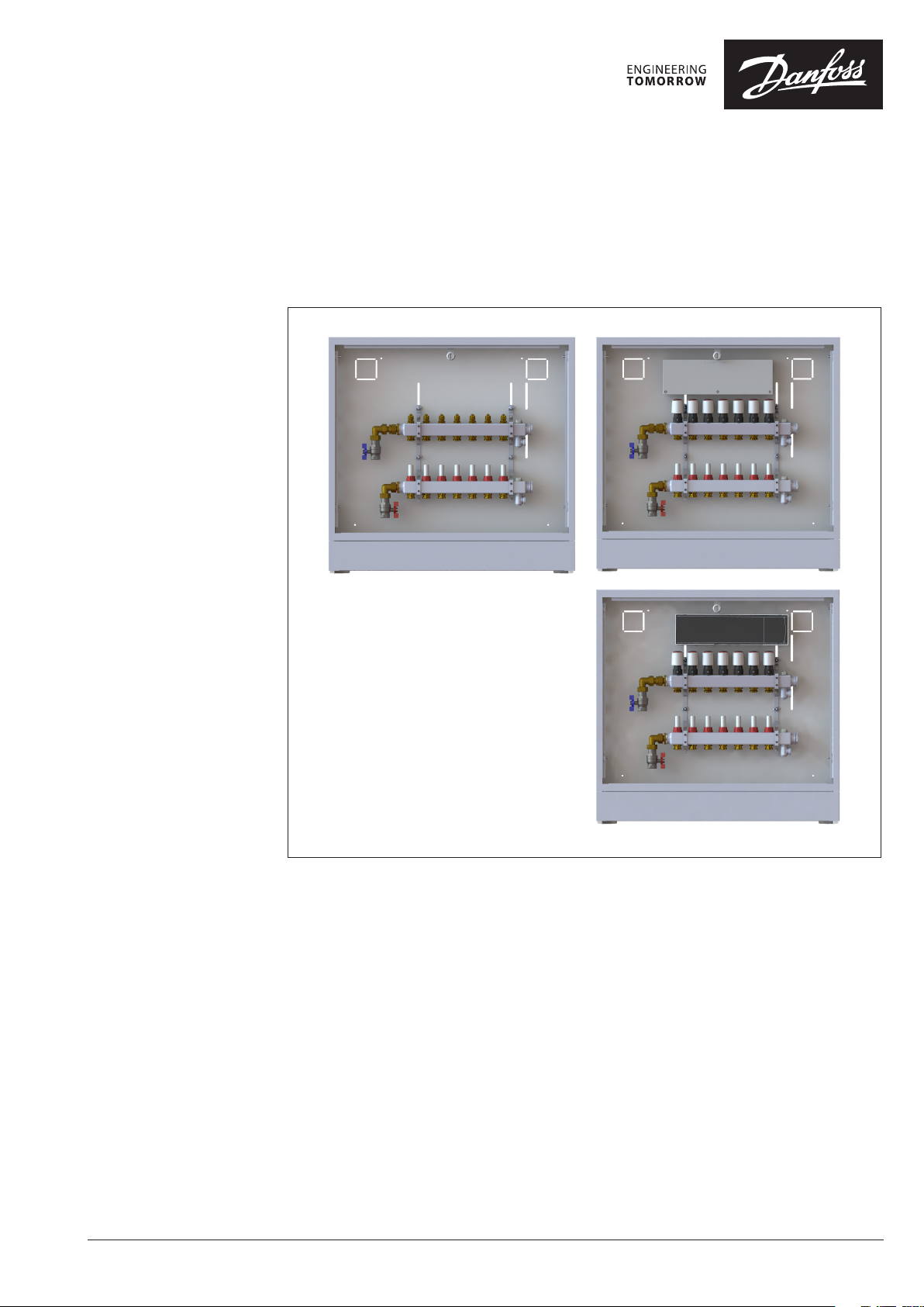
The Danfoss UnoFloor Light, Light C and Light Ci
are preassembled underfloor heating balancing
and control distribution units. UnoFloor comes
wired and premounted.
UnoFloor Light C includes Danfoss Icon™ 230V
Wiring Center and Light Ci comes with Danfoss
Icon™ 24V Master Controller.
The SSM stainless-steel manifold is used for
controlling water flow. Each tube of the floor
heating system is connected to the manifold,
thus making it possible to control water flow
or heat supply to each room in the building
individually.
Features:
• Compact design - fits in even
the smallest places
• In-wall cabinet ensures flush installation.
• Pre-mounted - minimal risk
of installation faults
• Easy ordering - only one number necessary
• Short installation time
• Correct heat distribution, even
under partial load
• Energy-saving
AI394049330652en-010201 | 1
Data sheet UnoFloor Light / Light C / Light Ci
213
104
84
Ordering
Description Typ e Code no.
The underfloor heating control
distribution unit includes:
• Stainless steel manifold
• Danfoss Icon 230V Wiring center
(Light C) or Icon 24V Master
Controller (Light Ci)
• Actuators (Light C and Ci)
• Cabinet
• Nominal pressure PN 6
• Max. Temperature 90 °C
• G ¾” internal thread
Use heating water according
VDI 2035 or ONORM H 5195.
Unofloor Light 4 Loops Left 088X3704
Unofloor Light 5 Loops Left 088X3705
Unofloor Light 6 Loops Left 088X3706
Unofloor Light 7 Loops Left 088X3707
Unofloor Light 8 Loops Left 088X3708
Unofloor Light 10 Loops Left 088X3710
Unofloor Light 12 Loops Left 088X3712
Unofloor Light C 4 Loops left Icon 230V 088X3714
Unofloor Light C 5 Loops left Icon 230V 088X3715
Unofloor Light C 6 Loops left Icon 230V 088X3716
Unofloor Light C 7 Loops left Icon 230V 088X3717
Unofloor Light C 8 Loops left Icon 230V 088X3718
Unofloor Light C 10 Loops left Icon 230V 088X3720
Unofloor Light C 12 Loops left Icon 230V 088X3722
Unofloor Light Ci 4 Loops left Icon 24V 088X3724
Unofloor Light Ci 5 Loops left Icon 24V 088X3725
Unofloor Light Ci 6 Loops left Icon 24V 088X3726
Unofloor Light Ci 7 Loops left Icon 24V 088X3727
Unofloor Light Ci 8 Loops left Icon 24V 088X3728
Unofloor Light Ci 10 Loops left Icon 24V 088X3730
Unofloor Light Ci 12 Loops left Icon 24V 088X3732
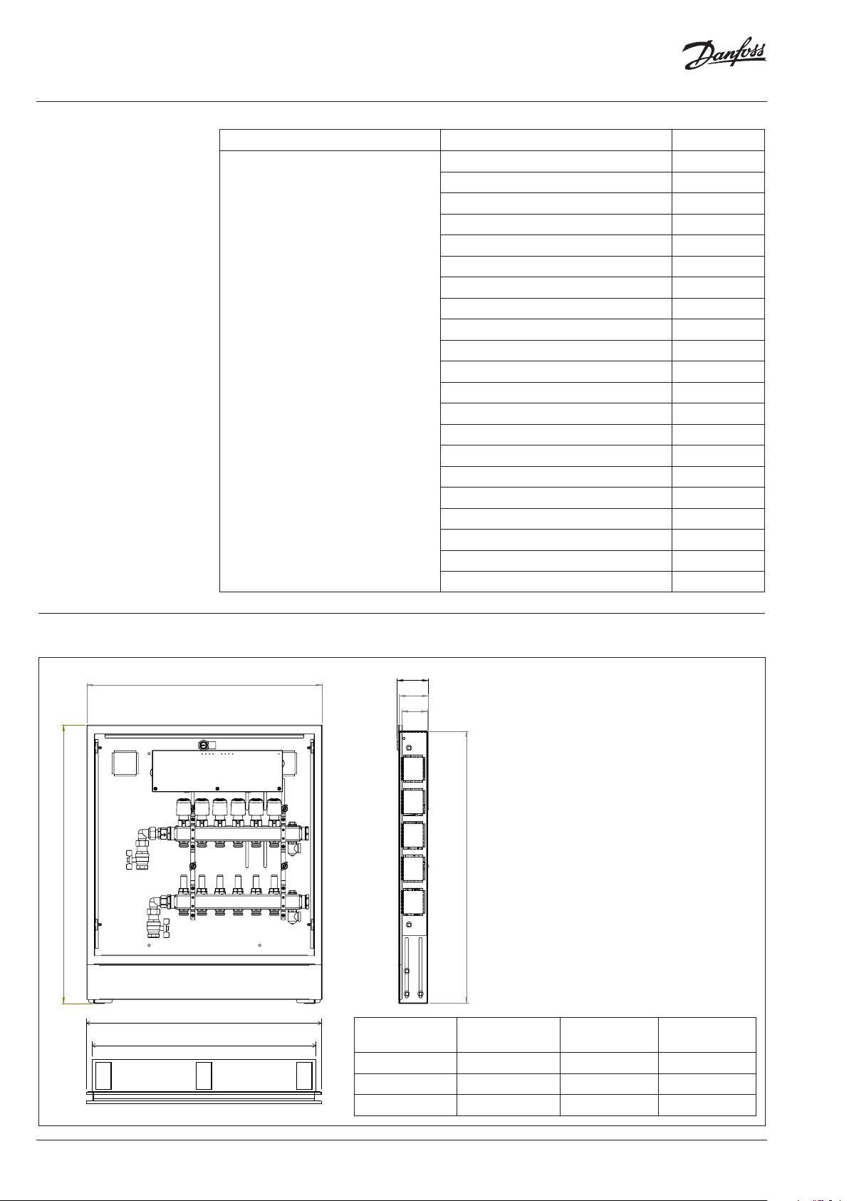
Dimensions
769
B
A
650
B
A
86
80
72
C
number of
circuits
A B C
4, 5, 6 610 mm 647 mm 750 mm
7, 8 760 mm 797 mm 750 mm
10, 12 960 mm 997 mm 750 mm
2 | © Danfoss | 2021.12
AI394049330652en-010201
Data sheet UnoFloor Light / Light C / Light Ci
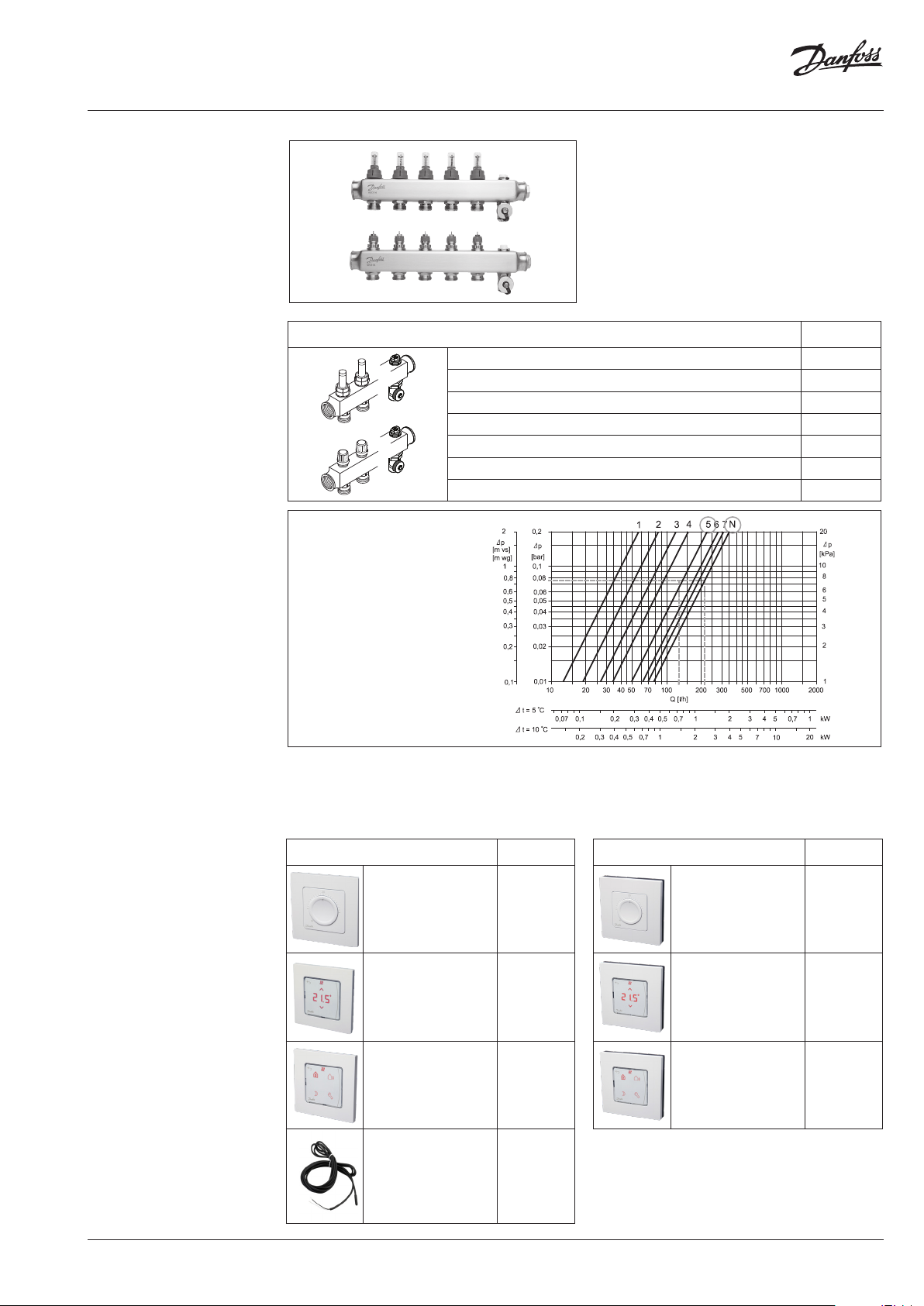
SSM
Floor Heating Manifold
Part of assembly
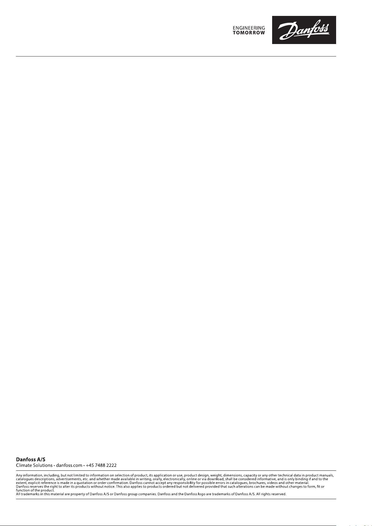
Pre-setting diagram
The SSM manifold is used for controlling water flow
in under floor heating systems. Each tube of the
floor heating system is connected to the manifold,
thus making it possible to control water flow or
heat supply to each room in the building individually.
Description Type
Manifold set 4+4, with flowmeter SSM-4F
Manifold set 5+5, with flowmeter SSM-5F
Manifold set 6+6, with flowmeter SSM-6F
Manifold set 7+7, with flowmeter SSM-7F
Manifold set 8+8, with flowmeter SSM-8F
Manifold set 10+10, with flowmeter SSM-10F
Manifold set 12+12, with flowmeter SSM-12F
Manifold,
with flowmeter
Presetting the manifold
valves
Accessories
The diagram shows the capacities for each heating
circuit at different presettings of the manifold valves.
Description Code no.
Danfoss Icon™ Dial,
In-wall
Danfoss Icon™
Display, In-wall
Danfoss Icon™
Programmable,
In-wall
Floor sensor 0 88 U1110
088U1000
088U1010
088U1020
Based on the above calculations and capacity diagram each manifold valve is preset by rotating the
red ring until the correct value on the ring is in-line
with the sight mark on the valve.
Description Code no.
Danfoss Icon™ Dial,
On-wall
Danfoss Icon™
Display, On-wall
Danfoss Icon™
Programmable,
On-wall
088U1005
088U1015
088U1025
AI394049330652en-010201
© Danfoss | 2021.12 | 3

Data sheet UnoFloor Light / Light C / Light Ci
TWA
Thermal Wax Actuator
(Light C and Light Ci)
Part of assembly
Technical specifications
The TWA is a small actuator for electrical on/off
controls to activate several types of valves and
floor heating manifolds.
Actuator Connection type Supply Voltage
TWA-A RA 230 V AC or 24 V AC/DC
Supply voltage 230 V (3 A pre-fuse) or 24 V (Class II (SELV))
Max. inrush current 230 V: 250 mA or 24 V: 250 mA
Frequency 50- 60 Hz
Running power consumption 2 W
Spindle travel time ~3 min .
Ambient temperature 0 °C to 60 °C
Enclosure IP 41
Cable length 950 mm
kvs (m³/H) 0,10 to 1,10
Max. ∆p (Bar) 0,6
Danfoss Icon 230V
Wiring Center
(Light C)
Danfoss Icon™ 230V Wiring Center is a connection
box for use in hydronic floor heating using 230V
thermostats and actuators.
The Icon™ 230V Wiring Center can connect up
to 14 thermal actuators from up to 8 room thermostats. It is provided with 230V Live circulation
pump output and a voltage-free relays for controlling a boiler. The relays are activated when one or
more thermostats require heat.
The Wiring Center also supports away and cooling
mode which can be controlled by a 230 V signal as
well as LED’s to indicate when outputs are active.
Mounting is made easy due to a simple layout of
the terminals and clear marking on the screw terminals. Mounting can be done by using screws.
4 | © Danfoss | 2021.12
AI394049330652en-010201

Data sheet UnoFloor Light / Light C / Light Ci
Technical data
Wiring
Max. number of thermostats 8
Max number of actuators 14
Supported actuator types Normally closed (NC)
Internal fuse 3 A
Conforms with diectives LVD, EMC, RoHs, WEEE
Supply voltage 220-240 V AC
Supply frequency 50/60 Hz
Output voltage, actuators 230 V AC
Ambient temp. range, operation 0 °C to 50 °C
Storage temp. range −20 °C to +60 °C
Output relay, pump 230 V Max. 100 W
Output relay, boiler Voltage-free Max. 2 A
Output cooling 230 V when active
Output Setback 230 V when active
Input Cooling External switch input (230 V rating)
Input setback External switch input (230 V rating)
Rated impulse voltage 4 kV
Temperature for ball pressure test 75 °C
Control pollution degree Pollution degree 2
Disposal instructions As electronic waste
Icon™ 230V Wiring Center
MAX. 100 W
L N
L N
3A
Mains
Option
220 -240 VAC
Option
2
Option
3
50/60 Hz
HE AT!
1
2× ≤ 1,5 mm
5 5 5
1 1 2 2 3 3 4 4 5 5 6 6 7 8
THE RMO STAT 1 THE RMOS TAT 2 THE RMOS TAT 3 THER MOS TAT 4 THER MOST AT 5 THER MOSTAT 6 THER MOSTAT 7 THERM OSTAT 8
SWITCH
EXTERNAL
L N
2× ≤ 1,5 mm
L N
LOAD
≤ 1,5 mm ≤ 1,5 mm ≤ 1,5 mm
L N
LOAD
L N
LOAD
L N
LOAD
L NN
L N
LOAD
Load
L
L N
LOAD
L N
LOAD
L N N NTC
Example: Icon™ ProgrammableExample: Icon™ DisplayExample: Icon™ Dial
LOAD
Options
Option
Load
L
Sensor
Option
4
AI394049330652en-010201
© Danfoss | 2021.12 | 5

Data sheet UnoFloor Light / Light C / Light Ci
Danfoss Icon™
Master Controller 24V
(Light Ci)
Technical data
Master Controller 24V and
Expansion Module (optional)
Danfoss Icon™ is a modular heating system for
individual room control. It can be configured as
a wired or wireless system or as a combination, if
required.
For all applications please see Installation guide for Expansion Module.
Supply voltage 220-240 V AC
Supply frequency 50/60 Hz
Output voltage, actuators 24 V DC
Max. power consumption per actuator output 2 W
Number of actuator outputs
(1 actuator per output terminal)
Output voltage, thermostats 24 V DC
Max. number of thermostats 10
Dimensions W: 370 mm, H: 100 mm, D: 53 mm
Encapsulation (IP Class) IP 20
The center of the system is the Danfoss Icon™
Master Controller 24 V, which configures and ties
the system together.
Installation and set-up of the Danfoss Icon™
Master Controller 24 V is made easy by using the
pre-defined application and intuitive touch user
interface.
10
6 | © Danfoss | 2021.12
AI394049330652en-010201

Data sheet UnoFloor Light / Light C / Light Ci
Tender text
Pre-assembled underfloor heating balancing and
control distribution unit must come wired and
pre-mounted, fitted in in-wall cabinet. Cabinet
must be painted in white (RAL 9016), 750 mm
in height, up to 960 mm in width and 80 mm in
depth.
The manifold is used for heat regulation in floor
heating systems. Each circuit in the floor heating
system is connected to the manifold, which
makes it possible to regulate the heat supply to
each room in the building independently.
The manifold shall consist of a flow and return
manifold where the flow manifold must be able
to close each circuit independently. The return
manifold must be equipped with presetting
valves, ensuring optimal balancing of the system.
Balancing of the floor heating system shall be
done on a swivel scale ranging from 1-7 and
N so that the value can be read and checked
after commissioning. Valves shall be controlled
electronically by thermal actuators installed
without adapters.
The manifold must be provided in modules of up
to 12 outlets with air vent and drain / fill function
valve. Ball valves must be available as an option
for positive shut-off between manifold and
system.
The manifold must be made of stainless steel
and have the following specifications:
• Maximum flow temperature : 90 °C
• Maximum differential pressure: 0,6 bar
• Maximum operating pressure with
flow meter: 6 bar
• Maximum operating pressure,
without flow meter: 10 bar
• Max Kv setting of the valve (N): 0,97 m
Light C:
It must be possible to connect the room
thermostats to the NC actuators via a connection
box.
The connection box must have not less
8 channels and 14 actuator outputs, have two
potential free relays: one for the pump and one
for the boiler. Distribution voltage: 230 V AC.
Voltage: 230 V AC, max. power per output: 3 W.
The actuator must be premounted on a valve.
The actuator receives a signal from the room
thermostat. Based on the signal, it opens and
closes the valve which makes it possible to
regulate the energy supply to each room in the
building independently. For easy and secure
installation, the actuator must be delivered
as one part (no adapter) and mounted on the
manifold by use of an Allen screw.
Light Ci:
It must be possible to connect the room
thermostats to the NC/NO actuators via
a connection box.
The connection box must have not less 10
channels and 10 actuator outputs, have
potential-free relay, one micro disconnection
output and permanent 230 V (max 50W) output.
Supply voltage: 230 V AC. Output voltage for
actuators: 24 V DC, max. power per output: 2 W.
It must be possible to set up to 10 actuators for
1 room thermostat. It must be possible to control
system by smartphone app and have pre-set
work profiles with applications. Connection box
must have possibility to be upgraded to wireless
solution by Wireless module. For accurate
hydronic control, automatic heat load control
feature must be available.
The actuator must be premounted on a valve.
The actuator receives a signal from the room
thermostat. Based on the signal, it opens and
closes the valve which makes it possible to
regulate the energy supply to each room in the
building independently. For easy and secure
installation, the actuator must be delivered
as one part (no adapter) and mounted on the
manifold by use of an Allen screw.
Accessories
AI394049330652en-010201
Frame and door for service are available on demand.
Description Code no.
Frame and door for cabinet 610 088X3008
Frame and door for cabinet 760 088X3010
Frame and door for cabinet 960 088X3012
© Danfoss | 2021.12 | 7
Data sheet UnoFloor Light / Light C / Light Ci
8 | © Danfoss | DCS-SDGPT/PL | 2021.12
AI394049330652en-010201
 Loading...