

Data sheet
UnoFloor Heating / Cooling
General description
and application
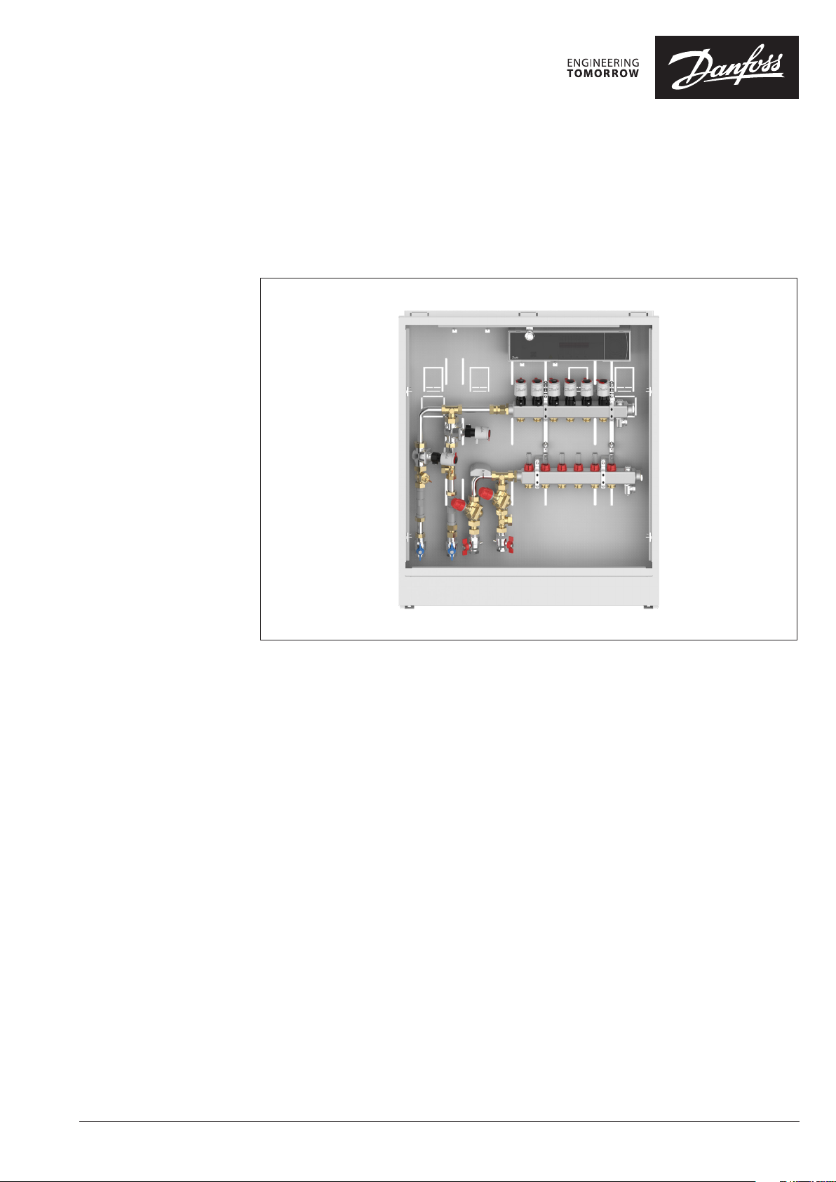
The Danfoss UnoFloor Heating / Cooling is
a preassembled pressure distribution unit for
4-pipe systems with floor heating and cooling.
UnoFloor comes wired and pre-mounted.
The UnoFloor’s Danfoss Icon™ Master controller
24V is modular heating center for individual
room control. It can be configured as a wired or
wireless system or as a combination, if required.
Can connect up to 10 thermal actuators and
room thermostats.
The SSM stainless-steel manifold is used for
controlling water flow. Each tube of the floor
heating and cooling system is connected to
the manifold, thus making it possible to control
water flow or heat supply to each room in the
building individually.
The The AB-PM set ensures optimal hydronic
balance. Flow limitation independent of
differential pressure is now guaranteed.
Together with Danfoss TWA electric
thermoactuators, RA-C valves make up a perfect
combination for control of cooling and heating
circuits.
Features:
• Compact design - fits in even
the smallest places
• In-wall cabinet ensures flush installation
• Pre-mounted - minimal risk
of installation faults
• Easy ordering - only one number necessary
• Short installation time
• Correct heat distribution, even
under partial load
• Reliable hydronic balancing
for lower heating costs
• Auto balancing provided by Danfoss
Icon™ Master controller
• Intuitive touch user interface
• Automatic change over for cooling
controlled by room thermostat
© Danfoss | 2022.03
AI399435840286en-010201 | 1
Data sheet UnoFloor Heating / Cooling
Ordering
Description Typ e Code no.
Pressure independent underfloor
heating and cooling unit with
balancing and control functions.
• Danfoss Icon Master controller 24V
with expansion module
• Actuators
• Stainless steel manifold
• AB-PM valves
with TWA-Q NC actuators
• RA-C 2-way valves
with TWA-A NC actuators
• Dew point sensor
• Cabinet
• Nominal pressure PN 6
• Max. Temperature 90 ° C
• G ¾” Internal thread
Use heating water according VDI 2035.
Unofloor H/C 4 Loops Left 088X3764
Unofloor H/C 5 Loops Left 088X3765
Unofloor H/C 6 Loops Left 088X3766
Unofloor H/C 7 Loops Left 088X3767
Unofloor H/C 8 Loops Left 088X3768
Unofloor H/C 10 Loops Left 088X3770
Unofloor H/C 11 Loops Left 088X3772
Unofloor H/C 4 Loops Right 088X3774
Unofloor H/C 5 Loops Right 088X3775
Unofloor H/C 6 Loops Right 088X3776
Unofloor H/C 7 Loops Right 088X3777
Unofloor H/C 8 Loops Right 088X3778
Unofloor H/C 10 Loops Right 088X3780
Unofloor H/C 11 Loops Right 088X3782
2 | © Danfoss | 2022.03
AI399435840286en-010201
Data sheet UnoFloor Heating / Cooling
Accessories
Description Code no. 24V Wireless
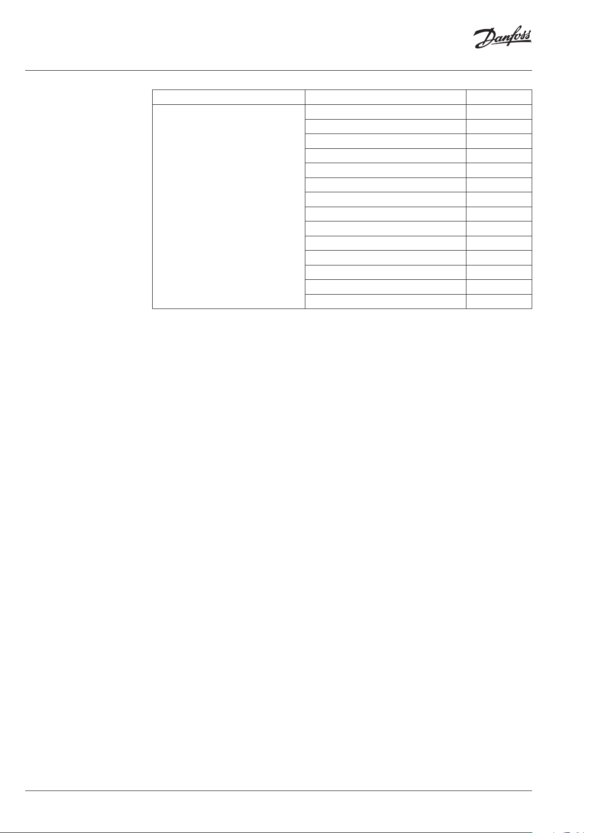
Danfoss Icon™ Display, In-wall 088U1050
Danfoss Icon™ Display, On-wall 088U1055
Danfoss Icon™ Display, On-wall 088U1081
Danfoss Icon™ Infrared, On-wall 088U1082
Floor sensor 088U1110
App module 088U1101
ZigBee Radio module 088U1130
Radio module
(not for inside cabinet installation)
Repeater 088U1102
Surface temperature sensor, ESM-11 087B1165
088U1103
AI399435840286en-010201
© Danfoss | 2022.03 | 3
Data sheet UnoFloor Heating / Cooling
SSM
Floor Heating Manifold
Part of assembly
Pre-setting diagram
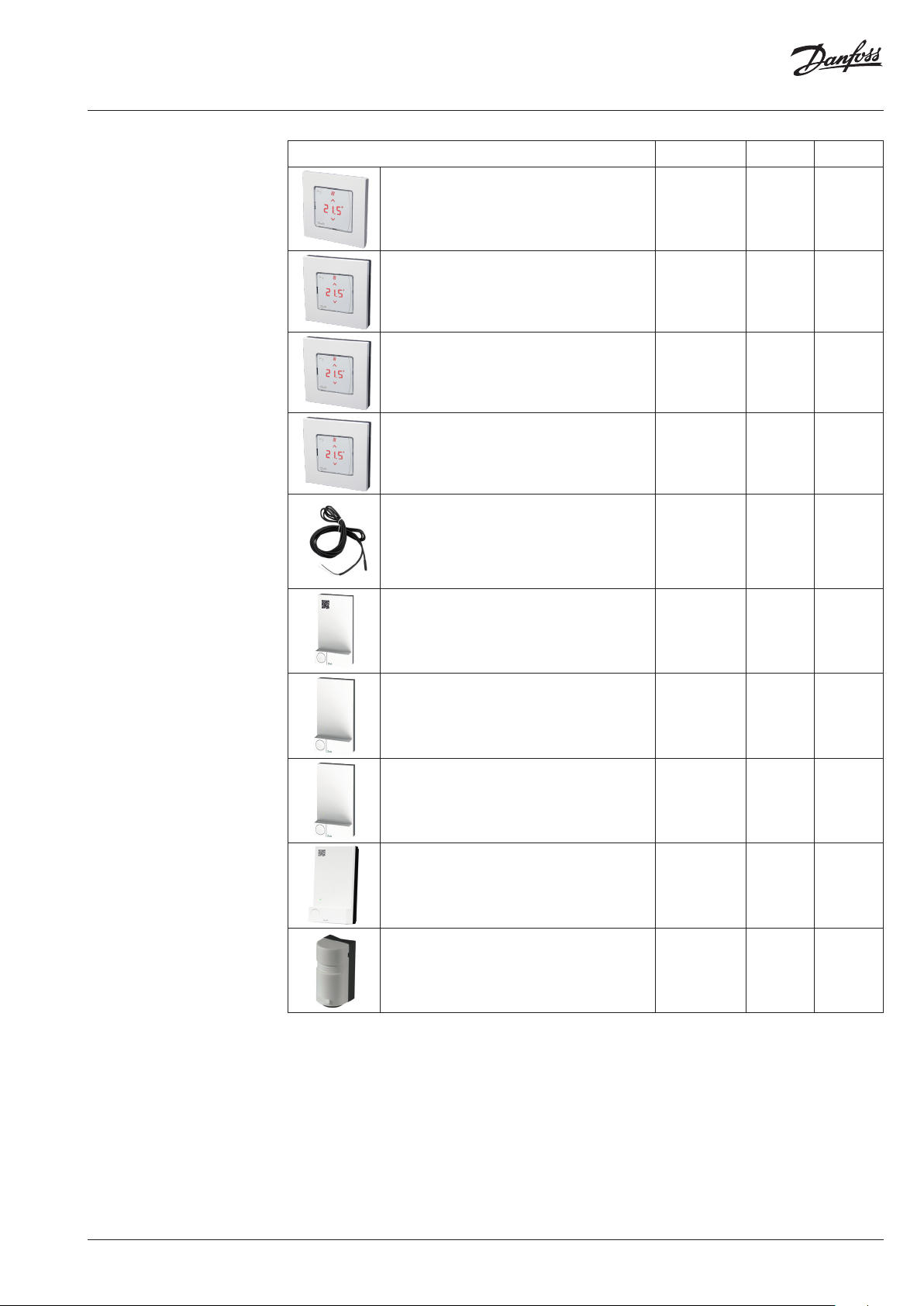
The SSM manifold is used for controlling water
flow in under floor heating systems. Each tube of
the floor heating system is connected to the
manifold, thus making it possible to control water
flow or heat supply to each room in the building
individually.
Description Type
Manifold set 4 + 4, with flowmeter SSM-4F
Manifold set 5 + 5, with flowmeter SSM-5F
Manifold set 6 + 6, with flowmeter SSM-6F
Manifold set 7 + 7, with flowmeter SSM-7F
Manifold set 8 + 8, with flowmeter SSM-8F
Manifold set 10 +10, with flowmeter SSM-10F
Manifold set 11 + 11, with flowmeter SSM-11F
Manifold,
with flowmeter
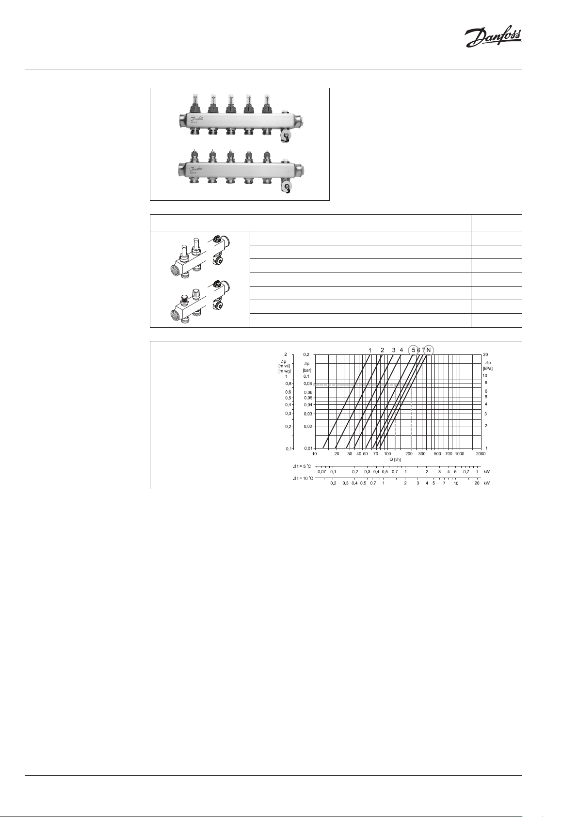
Presetting the manifold
valves
The diagram shows the capacities for each
heating circuit at different presettings of the
manifold valves.
Based on the above calculations and capacity
diagram each manifold valve is preset by rotating
the red ring until the correct value on the ring is
in-line with the sight mark on the valve.
4 | © Danfoss | 2022.03
AI399435840286en-010201

Data sheet UnoFloor Heating / Cooling
AB-PM DN 20 HP
balancing valve
Technical data
The AB-PM is an compact automatic balancing valve - designed for creating optimal
hydronic balance in horizontal loops - radiator and underfloor heating and cooling
applications. Flow limitation independent of
differential pressure is now guaranteed.
With TWA-Q actuator mounted on the valve,
AB-PM is be used as zone valve. When
connected to the room controller with time
programs, functions such as night setback,
holiday mode, etc become available.
Nominal diameter DN 20 HP
Qmax (at Δpr = 20 kPa) 600 l/h (at 100 % setting)
Upper limit of pressure controller at zero flow 35 kPa
Differential pressure (∆p for the valve + circuit) 28–400 kPa
Nominal maximal pressure 16 bar (PN 16)
Control valves characteristic Linear
Shut-off leakage rate Acc. to ISO 5208 class A - no visible leakage
Medium temperature −10 °C to +120 °C
CV stroke 2,25 mm
Connection Ext. thread ISO 228/1 G 1 A
Actuator M 30 × 1,5
Sizing AB-PM is to be sized based on manifold’s needed
flow (Q) [l/h], and needed differential pressure
drop for the loop (Δpr). Manifold pre-setting data
are presented on page 4. Max AB-PM flow data are
presented in table 1.
For any other Q and Δpr needed, AB-PM size and
setting can be indetified based on Fig. 1.
Typ e
DN 20 HP at
100% setting
Q max. 600 l/h 915 l/h
Maximum pressure drop
available for system at
20 kPa 10 kPa
max flow
Upper limit of pressure
controller at zero flow
Start required differential
pressure (for the valve)
35 kPa
8 kPa
DN 20 HP
100 %
90 %
80 %
70 %
60 %
50 %
40 %
30 %
20 %
flow [l/h]
∆pr [kPa]
Fig. 1
AI399435840286en-010201
© Danfoss | 2022.03 | 5

Data sheet UnoFloor Heating / Cooling
TWA-Q thermal actuator
Technical Data
Danfoss thermal actuator TWA-Q is used with
Danfoss Pressure Independent Control Valves
(PICV).
Power supply V 24 AC/DC, +25%/-20%
Max. inrush current A <0.25 (for <60 sec.)
Power consumption W < 2
Frequency Hz 50/60
Control input On/off and PWM
Closing force N 110±10
Min. stroke mm 5.0
Full stroke time
Max. medium temperature
Ambient temperature 2 … 60
Storage and transport temperature -40 … 70
Ambient humidity 95% r.h., non-condensing (according to EN 60730-1)
Protection class III
Grade of enclosure IP 54
Valve connection mm M30 × 1.5
Cable length m 1.2m or 5m PVC or 2m Halogen free
Weight kg 0.15
1)
at room tempe rature.
1)
min. < 3
95
° C
6 | © Danfoss | 2022.03
AI399435840286en-010201

Data sheet UnoFloor Heating / Cooling
Danfoss Icon™
Master Controller 24V
Technical data
Master Controller 24V and
Expansion Module
Danfoss Icon™ is a modular heating system for
individual room control. It can be configured as
a wired or wireless system or as a combination, if
required.
The center of the system is the Danfoss Icon™
Master Controller 24 V, which configures and ties
the system together.
Installation and set-up of the Danfoss Icon™
Master Controller 24 V is made easy by using the
pre-defined application and intuitive touch user
interface.
Supply voltage 220-240 V AC
Supply frequency 50/60 Hz
Output voltage, actuators 24 V DC
Max. power consumption per actuator output 2 W
Number of actuator outputs
(1 actuator per output terminal)
Output voltage, thermostats 24 V DC
Max. number of thermostats 10 or 15 depending on type of Master controller
Dimensions W: 370 mm, H: 100 mm, D: 53 mm
Encapsulation (IP Class) IP 20
10 or 15 depending on type of Master Controller
TWA-A
Thermal Wax Actuator
Ordering
Technical specifications
The TWA is a small actuator for electrical
on/off controls to activate several types of valves
and floor heating manifolds.
Actuator Connection type Supply Voltage Function
TWA-A RA 24 V AC/DC NC
Supply voltage 24 V (Class II (SELV))
Max. inrush current 350 mA
Frequency 50-60 Hz
Running power consumption 2 W
Spindle travel time ~3 min.
Ambient temperature 0 °C to 60 °C
Enclosure IP 41
Cable length 950 mm
kvs (m³/H) 0,10 to 1,10
Max. Δp (Bar) 0,6
AI399435840286en-010201
© Danfoss | 2022.03 | 7

Data sheet UnoFloor Heating / Cooling
RA-C cooling valve
Danfoss RA-C 2-way valves are used for controlling the
heating and cooling return line.
RA‑C 20 cooling valve
Valve
Connections
Presettings:
kv-value1), m3/h
1 2 3 N
RA-C 20 2 × G 1 A 0.80 1.10 1.70 2.60 3.30 10 bar 0.6 bar 16 bar 10 - 120°C
1)
The kv‑val ues show the flow (Q) in m3/h at a dif ferential pressure (∆p) of 1 bar thr ough the valve. At presettin g N the kv‑value is shown
at Xp = 3 K. The X p‑value decreases at lowe r presettings thus the kv ‑value at presetting 1 is show n at Xp = 1 K.
2)
The max. di fferential pressure spe cified is the maximum pre ssure at which the valves give satisfac tory regulation. As wi th any device
which imposes a p ressure drop on the system, no ise may occur under certain f low/pressure conditions. A dif ferential pressure bet ween 0.1
and 0.3 bar ac ross the valves is recommended. T he differential pressur e can be reduced using Danfoss dif ferential pressure regul ators. 2)
3)
Shut‑off PN10 approved.
kvsMax. working
pressure
3)
Max.
differential
pressure
Test pressure Water
2)
temperature
8 | © Danfoss | 2022.03
AI399435840286en-010201

Data sheet UnoFloor Heating / Cooling
Application guide
Reference
Thermostat
Heating supply
5
1
4
2
PWR3 IN 3 IN 2 IN 1
PT
24
1000
VDC
Cooling supply
Heating return
Cooling return
6
1
5
1
6
M M M M
1
M1 M2 M3 M4 M5
ACTUATOR OUTPUTS - 24V
PWR 2
PWR 1
RELAY
L N
L N
2
3
M6 M7 M8 M9
RADIO
MODULE
M10
APP
MODULE
LINK MASTER
BLUE
BROWN
Global away
(Switch or
timer)
4
V+
NC
NO
GND
COM
GREEN/YELLOW
5
3
6
Wi-Fi
GUIDE
22˚C
Parts list:
1. 2‑way valve RA‑C / AB‑PM
2. Danfoss manifolds (SSM‑F)
3. Thermal actuators 24 V TWA‑A
4. Dew point sensor type CF‑DS
5 & 6. Thermal actuator 24 V TWA‑A / TWA‑Q
AI399435840286en-010201
© Danfoss | 2022.03 | 9

Data sheet UnoFloor Heating / Cooling
213
104
84
A
B
Dimensions
C
15
B
30
23
110
66 96 67 84
number of
4, 5 753 mm 790 mm 939 mm
6, 7 864 mm 940 mm 939 mm
8, 10, 11 1057 mm 114 0 mm 939 mm
circuits
159
B
A
A B C
10 | © Danfoss | 2022.03
AI399435840286en-010201

Data sheet UnoFloor Heating / Cooling
Tender text
Pre-assembled pressure independent underfloor
heating balancing and control distribution unit
must come wired and pre-mounted, suitable
for left- and right-hand side connection to the
manifold, fitted in in-wall cabinet.
Cabinet must be painted in white (RAL 9016),
939 mm in height, up to 1140 mm in width and
110 mm in depth.
It must be possible to connect the room
thermostats to the NC/NO actuators via
a connection box. The connection box must
have not less 10 channels and 10 actuator
outputs, have potential free relay, one micro
disconnection output and permanent 230 V
(max 50W) output. Supply voltage: 230 V AC.
Output voltage for actuators: 24 V DC, max.
power per output: 2 W. It must be possible to
set up to 10 actuators for 1 room thermostat.
It must be possible to control system by
smartphone app and have pre-set work profiles
with applications. Connection box must have
possibility to be upgraded to wireless solution by
Wireless module. For accuracy hydronic control,
automatic heat load control feature must be
available.
The manifold shall consist of a flow and return
manifold where the flow manifold must be able
to close each circuit independently. The return
manifold must be equipped with presetting
valves, ensuring optimal balancing of the
system. Flow control of the floor heating system
shall be done on a visible presetting scale, so
that the value can be read and checked after
commissioning. Valves shall be controlled
electronically by thermal actuators installed
without adapters.
The manifold must be provided in modules with
air vent and drain / fill function valve.
The manifold must be made of stainless steel
and have the following specifications:
• Maximum flow temperature: 90 °C
• Maximum differential pressure: 0,6 bar
• Maximum operating pressure: 6 bar
• Max Kv setting of the valve (N): 0,97 m
The actuator must be pre-mounted on a valve.
The actuator receives a signal from the room
thermostat. Based on the signal, it opens and
closes the valve which makes it possible to
regulate the energy supply to each room in the
building independently. For easy and secure
installation, the actuator must be delivered
as one part (no adapter) and mounted on the
manifold by use of an Allen screw.
The pressure independent balancing and control
set must consist of a linear control valve, impulse
tube with adapters to it, connector to manifold.
The valve could be used as an automatic flow
limiter. The valve should have a mechanism
to adjust the flow from 100 % to 0 % of the
maximum flow. Maximum recommended flow
setting should not be more than 600 l/h at
maximum system pressure drop 10 kPa, and no
more than 915 l/h at maximum system pressure
drop 5 kPa. Shut off service function should be
possible with setting mechanism. The authority
of the pressure independent control valve should
be 1 at all settings (control valve characteristic is
not changed). Upper limit of pressure controller
at zero flow must be 35 kPa. (Supplier of the
valve should provide lab test results1). Nominal
pressure rating 16 bar. Valve should have
possibility to mount actuator.
Heating and cooling circuits shall include
a control valve, where it must be possible
to connect normally closed (TWA-A NC 24V)
actuator.
AI399435840286en-010201
© Danfoss | 2022.03 | 11

Data sheet UnoFloor Heating / Cooling
Accessories
Spare parts
Panels for on wall mounting are available on demand.
Description Code no.
On wall panels for cabinet 790 088X3026
On wall panels for cabinet 940 088X3028
On wall panels for cabinet 1140 088X3030
Frame and door for service are available on demand.
Description Code no.
Frame and door for cabinet 790 088X3020
Frame and door for cabinet 940 088X3022
Frame and door for cabinet 1140 088X3024
12 | © Danfoss | DCS-SGDPT/PL | 2022.03
AI399435840286en-010201
 Loading...