

Data Sheet
UnoFloor Control
Description
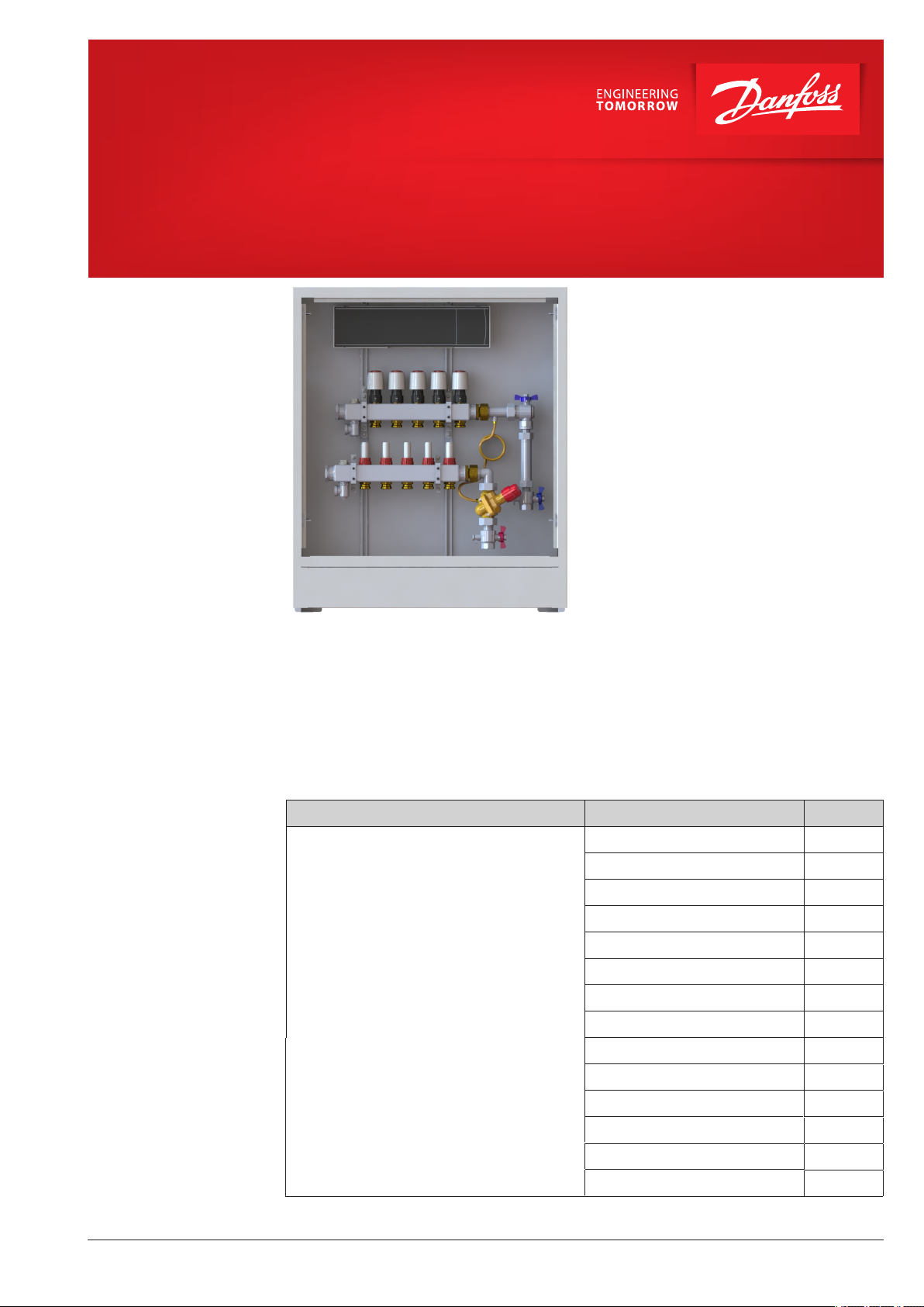
The Danfoss UnoFloor Control is a preassembled pressure independent underfloor
heating electronic balancing and control
distribution unit. UnoFloor comes wired and
pre-mounted. The UnoFloor’s Danfoss Icon™
Master controller 24V is modular heating
center for individual room control. It can be
configured as a wired or wireless system or as
a combination, if required. Can connect up to
10 thermal actuators and room thermostats.
The SSM stainless-steel manifold is used for
controlling water flow. Each tube of the floor
heating system is connected to the manifold,
thus making it possible to control water flow
or heat supply to each room in the building
individually.
The The AB-PM set ensures optimal hydronic
balance. Flow limitation independent of
differential pressure is now guaranteed.
Features:
• Compact design - fits in even the smallest
places.
• In-wall cabinet ensures flush installation.
• Pre-mounted - minimal risk of installation
faults.
• Easy ordering - only one number necessary.
• Short installation time.
• Correct heat distribution, even under partial
load.
• Reliable hydronic balancing for lower heating costs.
• Auto balancing provided by Danfoss Icon™
Master controller
• Intuitive touch user interface.
Ordering
Key UnoFloor Control 4L, Comfort - version, 4- number of circuits, L - left assembly, if R - right assembly
© Danfoss | 2020.03
Description Type
Pressure independent Underfloor heating
Electronic Balancing and control distribution unit
• Danfoss Icon Master controller 24V
• Actuators
Stainless steel manifold
•
• AB-PM set
• Cabinet
• Nominal pressure PN 6
• Max. Temperature 90 ° C
Use heating water according VDI 2035.
Code no.
UnoFloor Control 4L 088X3604
UnoFloor Control 5L 088X3605
UnoFloor Control 6L 088X3606
UnoFloor Control 7L 088X3607
UnoFloor Control 8L 088X3608
UnoFloor Control 10L 088X3610
UnoFloor Control 12L 088X361
UnoFloor Control 4R
UnoFloor Control 5R
UnoFloor Control 6R
UnoFloor Control 7R
UnoFloor Control 8R
UnoFloor Control 10R
UnoFloor Control 12R
AI333535898456en-000102 | 1
088X3624
088X3625
088X3626
088X3627
088X3628
088X3630
088X3632
2
Data Sheet UnoFloor Control
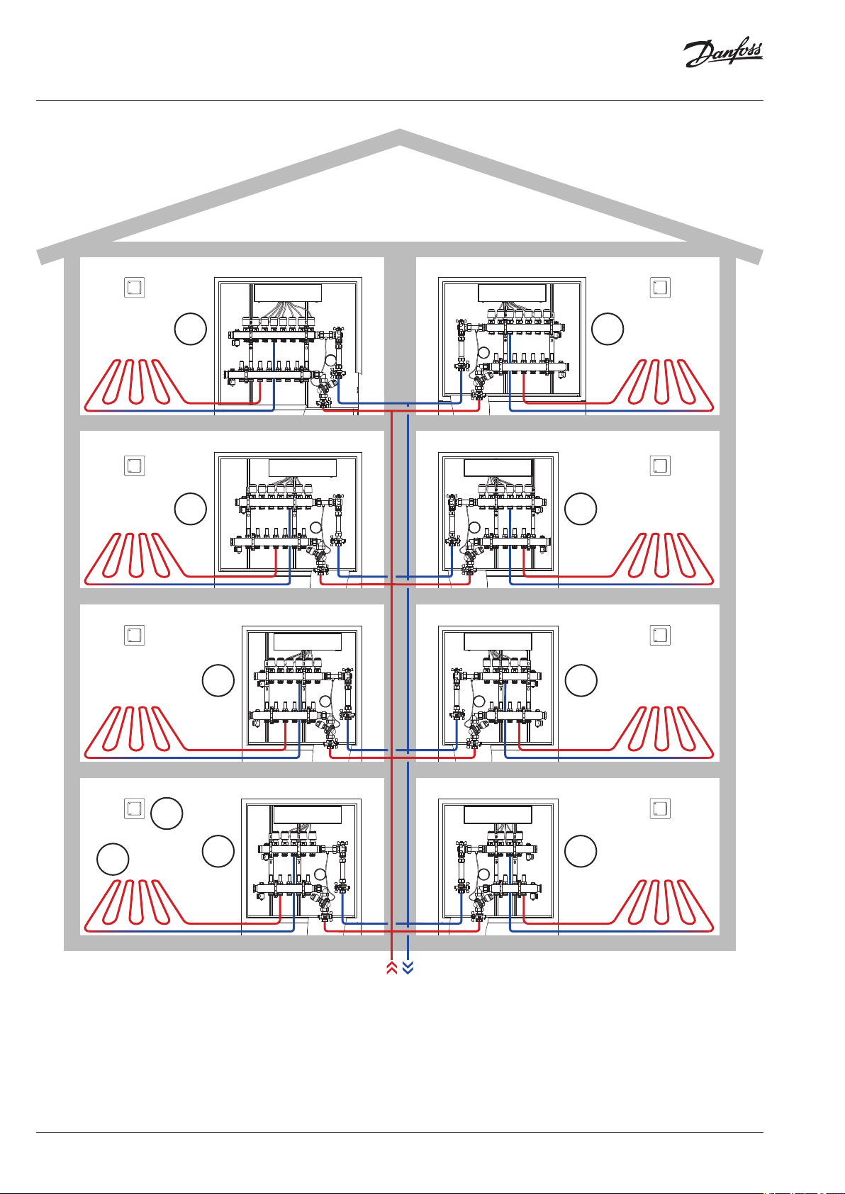
System
109
87
5
6
1
2
3
4
2 | © Danfoss | 2020.03
1. Room Thermostats
2. Underfloor heating circuit
3. UnoFloor Control 5R
4. UnoFloor Control 4L
5. UnoFloor Control 6R
6. UnoFloor Control 5L
7. UnoFloor Control 7R
8. UnoFloor Control 6L
9. UnoFloor Control 8R
10. UnoFloor Control 7L
AI333535898456en-000102
Data Sheet UnoFloor Control
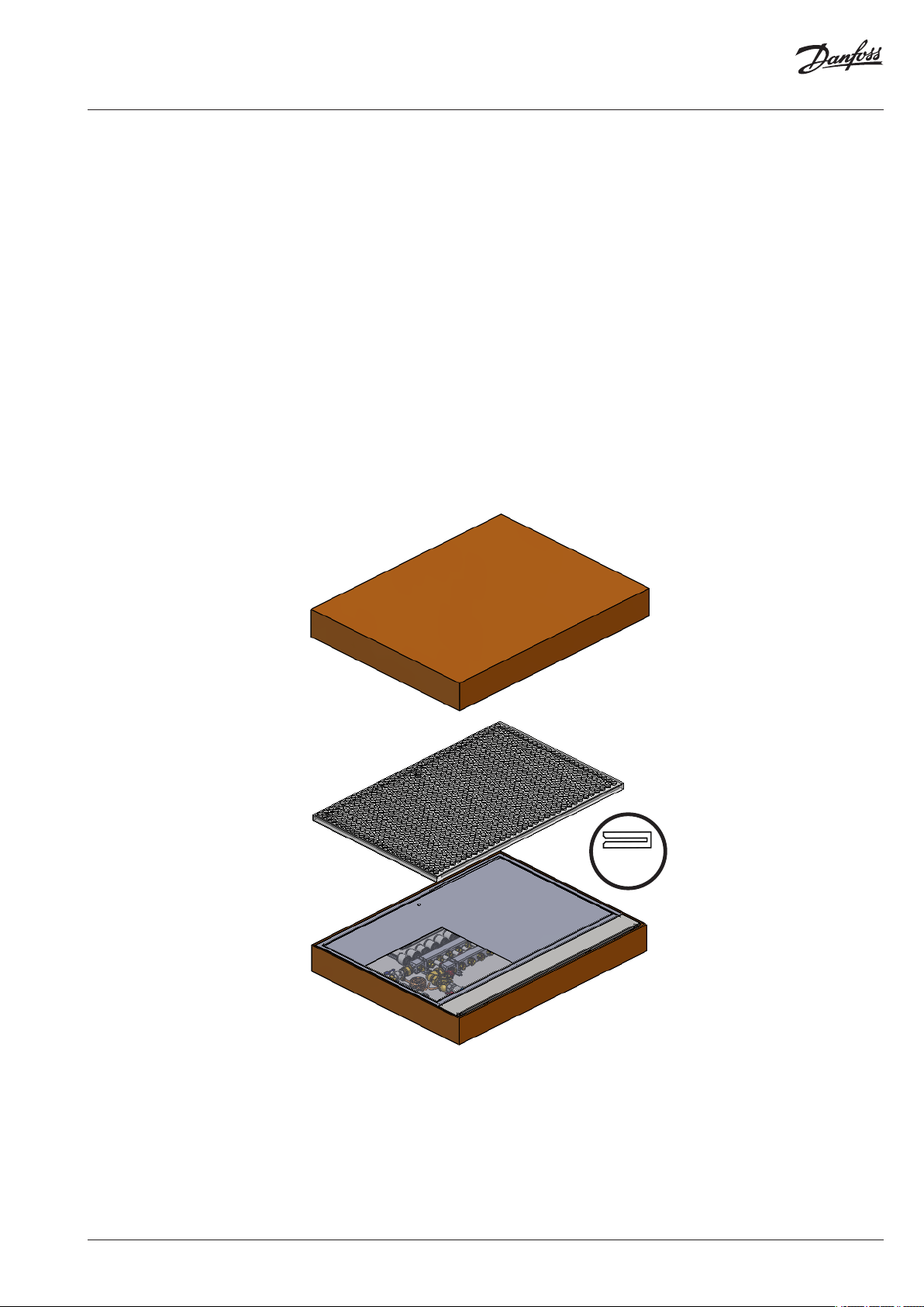
UnoFloor Control is a
Time saving provider
Take the prefab for each apartment and put away frame and door which are packed
together for protection. The cardboard box can be used to protect frames and doors
construction phase
Time saving solution provider:
• Manifold mounted in the cabinet
• premounted AB-PM set
• I
con Master Controller fixed
• All TWA actuators are wired with the Icon Master Controller
.
during
© Danfoss | 2020.03
x4
AI333535898456en-000102 | 3

Data Sheet UnoFloor Control
Accessories
Description
Danfoss Icon™ Display, In-wall
Danfoss Icon™ Display, On-wall
Danfoss Icon™ Display, On-wall
Danfoss Icon™ Infrared, On-wall
Floor sensor
Code no.
088U1050
088U1055
088U1081
088U1082
088U1110
24V
Wireless
App module
ZigBee Radio module 088U1130
Radio module
(not for inside cabinet installation)
Repeater
Expansion module
Dew-point sensor
088U1101
088U1103
088U1102
088U1100
088U0251
4 | © Danfoss | 2020.03
Surface temperature sensor, ESM-11
087B 1165
AI333535898456en-000102

Data Sheet UnoFloor Control
SSM
Floor Heating Manifold
Part of assembly
Pre-setting diagram
The SSM manifold is used for controlling water
flow in under floor heating systems. Each tube
of the floor heating system is connected to the
manifold, thus making it possible to control
water flow or heat supply to each room in the
building individually.
Description Type
Manifold set 4+4, with flowmeter SSM-4F
Manifold set 5+5, with flowmeter SSM-5F
Manifold set 6+6, with flowmeter SSM-6F
Manifold set 7+7, with flowmeter SSM-7F
Manifold set 8+8, with flowmeter SSM-8F
Manifold set 10+10, with flowmeter SSM-10F
Manifold set 12+12, with flowmeter SSM-12F
Manifold with
flowmeter
Presetting the manifold valves
© Danfoss | 2020.03
The diagram shows the capacities for each heating
circuit at different presettings of the manifold
valves.
Based on the above calculations and capacity
diagram each manifold valve is preset by rotating
the red ring until the correct value on the ring is
in-line with the sight mark on the valve.
AI333535898456en-000102 | 5

Data Sheet UnoFloor Control
AB-PM DN20 HP set
vertical
Part of assembly
Technical data
The AB-PM connection set is an compact and time
saving configuration – designed for creating optimal hydronic balance in horizontal loops - radiator
and underfloor heating applications. Flow limitation independent of differential pressure is now
guaranteed. It can be combined with most types
of manifolds, heat mete
rs and manifold cabinets.
One packing unit contains the following products:
• AB-PM valve
• Impulse tube, 1,5 m, R 1/16
• Adapter R 1/16 for AB-PM impulse tube connection
• 3-piece ball valve with connection for impulse
tube heat meter
• Adapter for heat meter
•
Connector/bracket for underfloor heating distributor G 1 A
External thread
connection to underfloor
heating distributor
(ISO 2 28/1)
Typ e
External thread
AB-PM
(ISO 2 28/1)
AB-PM DN20 HP set vertical G 1 A G 1 A
Nominal diameter DN 20 HP
Qmax (at Δp
r = 20 kPa) 600 l/h (at 100 % setting)
Upper limit of pressure controller at zero flow 35 kPa
Differential pressure (Δp for the valve + circuit) 28 – 400 kPa
Nominal maximal pressure 16 bar (PN 16)
Control valves characteristic Linear
Shut-off leakage rate Acc. to ISO 5208 class A - no visible leakage
Medium temperature -10 °C to +120 °C
CV stroke 2,25 mm
Connection Ext. thread ISO 228/1 G 1 A
Actuator M 30 × 1,5
Sizing
6 | © Danfoss | 2020.03
AB-PM is to be sized based on manifold’s needed
flow (Q) [l/h], and needed differential pressure
drop for the loop (Δpr). Manifold pre-setting data
are presented on page 4. Max AB-PM flow data are
presented in table 1.
For any other Q and Δpr needed, AB-PM size and
setting can be indetified based on Fig. 1.
Typ e
DN 20 HP at
100% setting
Q max. 600 l/h 915 l/ h
Maximum pressure drop
available for system at
20 kPa 10 kPa
max flow
Upper limit of pressure
controller at zero flow
Start required differential
pressure (for the valve)
35 kPa
8 kPa
DN 20 HP
100 %
90 %
80 %
70 %
60 %
50 %
40 %
30 %
20 %
flow [l/h]
˜ pr [kPa]
Fig. 1
AI333535898456en-000102

Data Sheet UnoFloor Control
Danfoss Icon™
Master Controller 24V
Technical data
Master Controller 24V and
Expansion Module (optional)
Danfoss Icon™ is a modular heating system for
individual room control. It can be configured as
a wired or wireless system or as a combination, if
required.
The center of the system is the Danfoss Icon™
Master Controller 24 V, which configures and ties
the system together.
Installation and set-up of the Danfoss Icon™
Master Controller 24 V is made easy by using the
pre-defined application and intuitive touch user
interface.
For all applications please see Installation guide for Expansion Module.
Supply voltage 220-240 V AC
Supply frequency 50/60 Hz
Output voltage, actuators 24 V DC
Max. power consumption per actuator output 2 W
Number of actuator outputs
(1 actuator per output terminal)
Output voltage, thermostats 24 V DC
Max. number of thermostats 10
Dimensions W: 370 mm, H: 100 mm, D: 53 mm
Encapsulation (IP Class) IP 20
10
TWA
Thermal Wax Actuator
Ordering
Technical specifications
The TWA is a small actuator
for electrical on/off controls to
activate several types of valves
and floor heating manifolds.
Actuator Connection type Supply Voltage Function
TWA-A RA 24 V AC/DC NC
Supply voltage 24 V (Class II (SELV))
Max. inrush current 350 mA
Frequency 50-60 Hz
Running power consumption 2 W
Spindle travel time ~3 min.
Ambient temperature 0 °C to 60 °C
Enclosure IP 41
Cable length 950 mm
kvs (m³/H) 0,10 to 1,10
Max. Δp (Bar) 0,6
© Danfoss | 2020.03
AI333535898456en-000102 | 7

Data Sheet UnoFloor Control
Dimensions
0-70
0-70
Number
of circuits
4, 5, 6 610 mm 647 mm
7, 8 760 mm 797 mm
10, 12
A B
960 mm
997 mm 750 mm
110
C
750 mm
750
mm
C
145
130
104
0-80
84
B
A
8 | © Danfoss | 2020.03
AI333535898456en-000102

Data Sheet UnoFloor Control
Tender text
Pre-assembled pressure independent underfloor
heating electronic balancing and control distribution unit must come wired and pre-mounted,
suit-able
connection to the manifold, fitted in in-wall
cabinet.
Cabinet must be painted in white (RAL 9016), 750
mm in height, up to 960 mm in width and 110
mm in depth.
It must be possible to connect the room thermostats to the NC/NO actuators via a connection
box. The connection box must have not less 10
chan-nels and 10 actuator outputs, have potential
free relay, one micro disconnection output and
perma-nent 230 V (max 50W) output. Supply
voltage: 230 V AC. Output voltage for actuators:
24 V DC, max. power per output: 2 W. It must be
possible to set up to 10 actuators for 1 room
thermostat. It must be possible to control system
by smartphone app and have presetted work
profiles with applica-tions. Connection box must
have possibility to be upgraded to wireless
solution by Wireless mod-ule. For accuracy
hydronic control, automatic heat load control
feature must be available.
The manifold is used for heat regulation in floor
heating systems. Each circuit in the floor heating
system is connected to the manifold, which
makes it possible to regulate the heat supply
to each room in the building independently.
The manifold shall consist of a flow and return
manifold where the flow manifold must be able
to close each circuit independently. The return
mani-fold must be equipped with presetting
valves, ensuring optimal balancing of the
system. Flow control of the floor heating system
shall be done on a visible presetting scale, so that
the value can be read and checked after
commissioning. Valves shall be controlled
electronically by thermal ac-
for left- and right-hand side
tuators installed without adapters.
The manifold must be provided in modules with
air vent and drain / fill function valve.
The manifold must be made of stainless steel and
have the following specifications:
• Maximum flow temperature : 90 °C
• Maximum differential pressure: 0,6 bar
• Maximum operating pressure: 6 bar
• Max Kv setting of the valve (N): 0,97 m
The actuator must be pre-mounted on a valve.
The actuator receives a signal from the room thermostat. Based on the signal, it opens and closes
the valve which makes it possible to regulate
the energy supply to each room in the building
independently. For easy and secure installation,
the actuator must be delivered as one part (no
adapter) and mounted on the manifold by use of
an Allen screw.
The pressure independent balancing and control
set must consist of a linear control valve, impulse
tube with adapters to it, 3-piece ball valve with
connection to impulse tube and heat meter, connector to manifold . The valve could be used as an
automatic flow limiter. The valve should have a
mechanism to adjust the flow from 100 % to 0 %
of the maximum flow. Maximum recommended
flow setting should not be more than 600 l/h at
maximum system pressure drop 10 kPa, and no
more than 915 l/h at maximum system pressure
drop 5 kPa. Shut off service function should be
possible with setting mechanism. The authority
of the pressure independent control valve should
be 1 at all settings (control valve characteristic is
not changed). Upper limit of pressure controller at
zero flow must be 35 kPa. (Supplier of the valve
should provide lab test results1). Nominal pressure
rating 16 bar.
Accessories
Spare parts
© Danfoss | 2020.03
Panels for on wall mounting are available on demand.
Description
On wall panels for cabinet
On wall
panels for cabinet 760
On wall panels for cabinet 960
Frame and door for service are available on demand.
Description
Frame and door for cabinet 610
Frame
and door for cabinet 760
Frame and door for cabinet 960
610
Code no.
088X3014
088X3016
088X3018
Code no.
088X3008
088X301
088X3012
0
AI333535898456en-000102 | 9

Danfos
s can accept no responsibility for possible errors in catalogues, brochures and o ther printed material. Danfoss reserves the right to alter its products w ithout notice. This also applies to
produc
ts already on order provided that such alterations can be m ade without subsequential changes being necessary in speciÿcations already agreed.
Al
l trademarks in this material are p roperty of the respective companies. Danfoss and all Danfoss logot ypes are trademarks of Danfoss A/S. All rights reserve d.
Danfoss A/S
Heating Segment • heating
.danfoss.com • +45 7488 2222 • E-Mail: heating@danfoss.com
10 | © Danfoss | 2020.03
AI333535898456en-000102
 Loading...