

Data Sheet
UnoFloor Basic
Description
Ordering
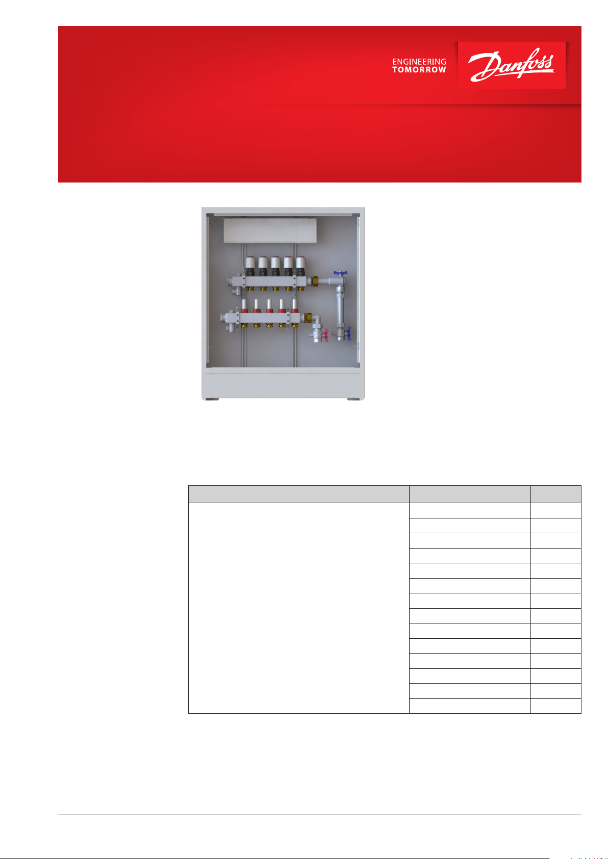
The Danfoss UnoFloor Basic is a pre-assembled
underfloor heating balancing and control
distribution unit. UnoFloor comes wired and premounted. The UnoFloor’s Danfoss Icon™ 230V
Wiring center can connect up to 14 thermal
actuators and 8 room thermostats. It is provided
with 230V Live circulation pump output and a
potential-free relays for controlling a boiler.
The SSM stainless-steel manifold is used for controlling water flow. Each tube of the floor heating
system is connected to the manifold, thus making
it possible to control water flow or heat supply to
each room in the building individually.
Features:
• Compact design — fits in even the smallest places.
• In-wall cabinet ensures flush installation.
• Heat meter connection set with ball valves.
• Pre-mounted — minimal risk of installation
faults.
• Easy ordering — only one number necessary.
• Short installation time.
Description Typ e Code no.
UnoFloor Basic 4L
UnoFloor Basic 5L
UnoFloor Basic 6L
Underfloor heating balancing and control distribution
unit includes:
• Danfoss Icon™ Wiring center 230V;
• Actuators;
• Stainless steel manifold;
• Heat meter set;
• Cabinet;
• Max differential pressure 0,6 bar;
• Nominal pressure: PN6;
• Max temperature: 90 °C.
Use heating water according VDI 2035.
Key UnoFloor Basic 4L: Basic — version, 4 — number of circuits, L — left assembly, if R — right assembly.
UnoFloor Basic 7L
UnoFloor Basic 8L
UnoFloor Basic 10L 088X3110
UnoFloor Basic 12L 088X3112
UnoFloor Basic 4R
UnoFloor Basic 5R
UnoFloor Basic 6R
UnoFloor Basic 7R
UnoFloor Basic 8R
UnoFloor Basic 10R
UnoFloor Basic 12R
088X3104
088X3105
088X3106
088X3107
088X3108
088X3124
088X3125
088X3126
088X3127
088X3128
088X3130
088X3132
© Danfoss | 2021.12
AI333531652454en-000103 | 1
Data Sheet UnoFloor Basic
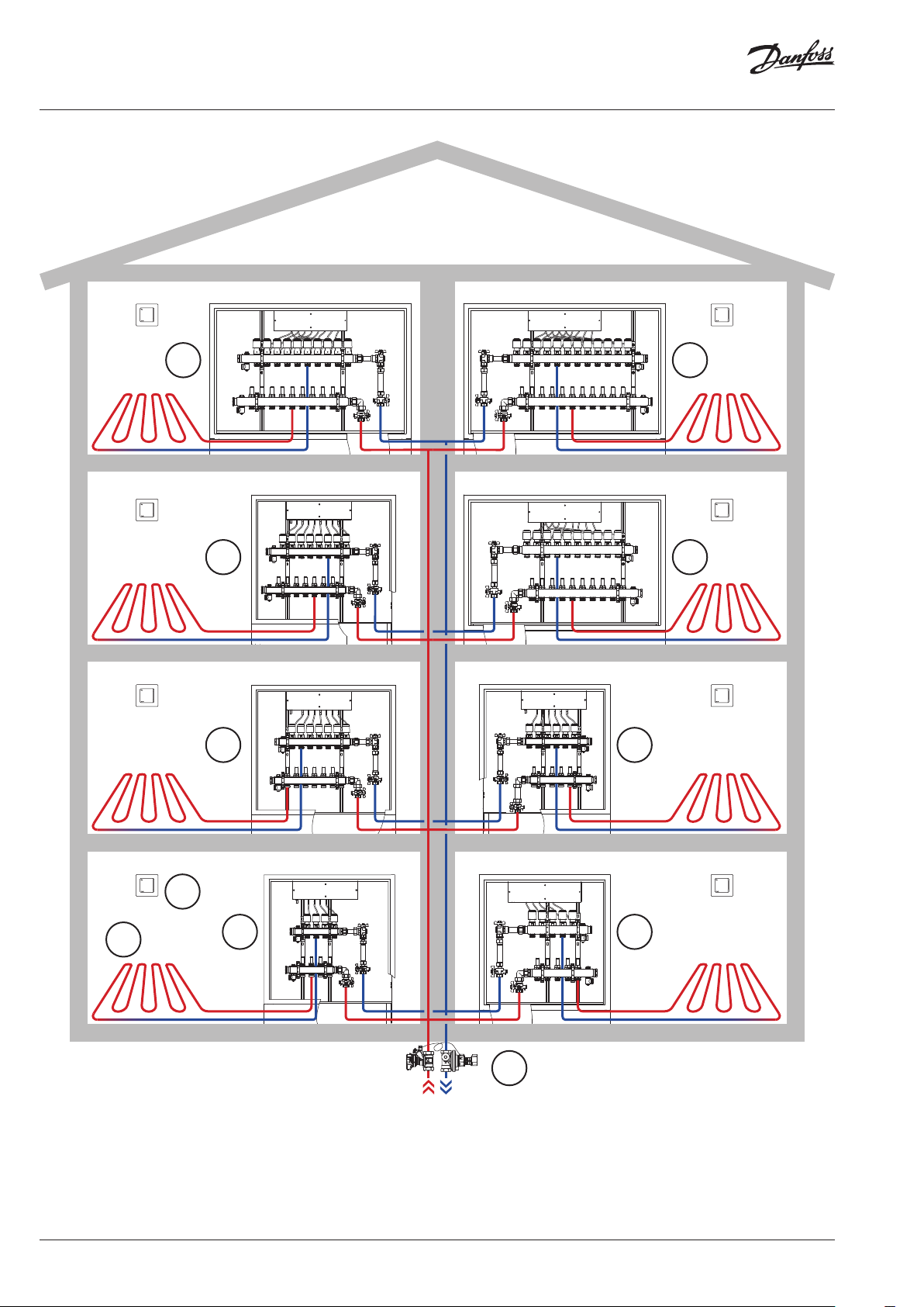
System
109
87
5
6
1
2
3
4
2 | © Danfoss | 2021.12
1. Room Thermostats
2. Underfloor heating circuit
3. UnoFloor Basic 4R
4. UnoFloor Basic 5L
5. UnoFloor Basic 7R
11
6. UnoFloor Basic 6L
7. UnoFloor Basic 8R
8. UnoFloor Basic 10L
9. UnoFloor Basic 10R
10. UnoFloor Basic 12L
11. ASV Automatic balancing valves
AI333531652454en-000103
Data Sheet UnoFloor Basic
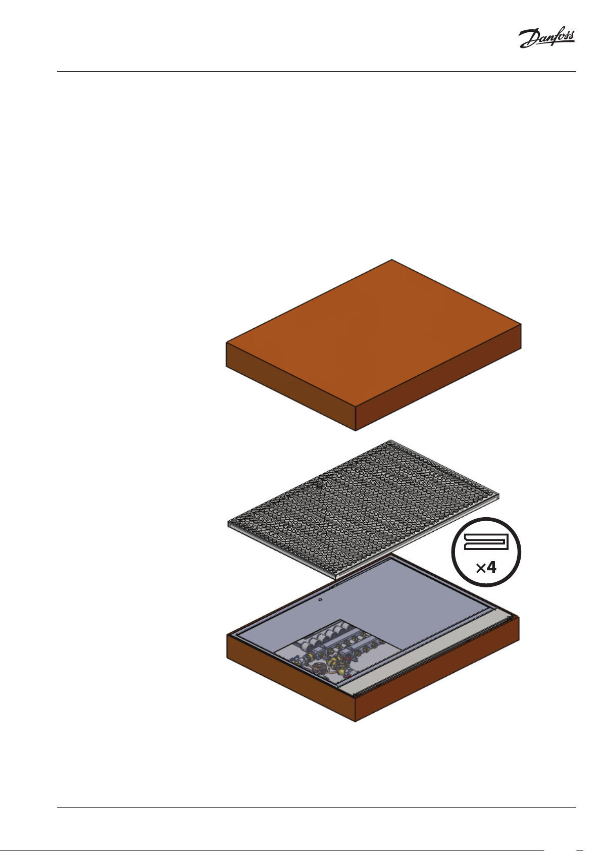
UnoFloor Basic is a Time
saving provider
Time saving solution provider:
• Manifold mounted in the cabinet;
• Premounted heat meter set;
• Icon™ Wiring center fixed;
• All TWA actuators are wired with the Icon™ Wiring center.
Take the prefab for each apartment and put away frame and door which are packed together for protection. The cardboard box can be used to protect frames and doors during construction phase.
© Danfoss | 2021.12
AI333531652454en-000103 | 3

Data Sheet UnoFloor Basic
Accessories
Description Code no.
Danfoss Icon™ Dial, In-wall 088U1000
Danfoss Icon™ Display, In-wall 088U1010
Danfoss Icon™ Programmable, In-wall 088U1020
Danfoss Icon™ Dial, On-wall 088U1005
Danfoss Icon™ Display, On-wall 088U1015
Accessories
Danfoss Icon™ Programmable, On-wall 088U1025
Floor sensor 088 U1110
Panels for on wall mounting are available on demand.
Description Code no.
On wall panels for cabinet 610 088X3014
On wall panels for cabinet 760 088X3016
On wall panels for cabinet 960 088X3018
Accessories
4 | © Danfoss | 2021.12
Frame and door for service are available on demand.
Description Code no.
Frame and door for cabinet 610 088X3008
Frame and door for cabinet 760 088X3010
Frame and door for cabinet 960 088X3012
AI333531652454en-000103

Data Sheet UnoFloor Basic
SSM
Floor Heating Manifold
Part of assembly
The SSM manifold is used for controlling water flow
in under floor heating systems. Each tube of the
floor heating system is connected to the manifold,
thus making it possible to control water flow or heat
supply to each room in the building individually.
Manifold set 5+5, with flowmeter
Description Type
Manifold set 4+4, with flowmeter SSM-4F
Manifold set 5+5, with flowmeter SSM-5F
Manifold set 6+6, with flowmeter SSM-6F
Manifold set 7+7, with flowmeter SSM-7F
Manifold set 8+8, with flowmeter SSM-8F
Manifold set 10+10, with flowmeter SSM-10F
Manifold set 12+12, with flowmeter SSM-12F
Pre-setting diagram
Presetting the manifold
valves
Heat meter set, connection: 3/4” × 110 mm 1” AG FBH-WMZ
Manifold,
with flowmeter
Pre-setting:
Room 1 N
Room 2 5
The diagram shows the capacities for each heating
circuit at different presettings of the manifold
valves.
Based on the above calculations and capacity
diagram each manifold valve is preset by rotating
the red ring until the correct value on the ring is
in-line with the sight mark on the valve.
© Danfoss | 2021.12
AI333531652454en-000103 | 5

Data Sheet UnoFloor Basic
Danfoss Icon™
230V Wiring Center
Technical data
Danfoss Icon™ 230V Wiring Center is a connection
box for use in hydronic floor heating using 230V
thermostats and actuators.
The Icon™ 230V Wiring Center can connect up
to 14 thermal actuators from up to 8 room thermostats. It is provided with 230V Live circulation
pump output and a voltage-free relays for controlling a boiler. The relays are activated when one or
more thermostats require heat.
Max. number of thermostats 8
Max number of actuators 14
Supported actuator types Normally closed (NC)
Internal fuse 3 A
Conforms with diectives LVD, EMC, RoHs, WEEE
Supply voltage 220-240 V AC
Supply frequency 50/60 Hz
Output voltage, actuators 230 V AC
Ambient temp. range, operation 0 °C to 50 °C
Storage temp. range −20 °C to +60 °C
Output relay, pump 230 V Max. 100 W
Output relay, boiler Voltage-free Max. 2 A
Output cooling 230 V when active
Output Setback 230 V when active
Input Cooling External switch input (230 V rating)
Input setback External switch input (230 V rating)
Rated impulse voltage 4 kV
Temperature for ball pressure test 75 °C
Control pollution degree Pollution degree 2
Disposal instructions As electronic waste
Wiring
Danfoss Icon™ 230V Wiring Center
L N
2
3
4
5 5 5
L N
3A
1
1 1 2 2 3 3 4 4 5 5 6 6 7 8
L N
L N
LOAD
L N
LOAD
L N
LOAD
L N
LOAD
L NN
L N
LOAD
Load
L
L N
LOAD
LOAD
L N
LOAD
Load
L N N NTC
L
6 | © Danfoss | 2021.12
AI333531652454en-000103

Data Sheet UnoFloor Basic
TWA
Thermal Wax Actuator
Part of assembly
Technical specifications
The TWA is a small actuator
for electrical on/off controls to
activate several types of valves
and floor heating manifolds.
Actuator Connection type Supply Voltage Function
TWA-A RA 230 V AC NC
Supply voltage 230 V (3 A pre-fuse)
Max. inrush current 230 V: 250 mA
Frequency 50-60 Hz
Running power consumption 2 W
Spindle travel time ~3 min.
Ambient temperature 0 °C to 60 °C
Enclosure IP 41
Cable length 950 mm
kvs (m³/H) 0,10 to 1,10
Max. Δp (Bar) 0,6
Dimensions
0-70
0-70
110
0-80
213
130
104
84
© Danfoss | 2021.12
Number
of circuits
4, 5, 6 610 mm 647 mm 750 mm
7, 8 760 mm 797 mm 750 mm
10, 12 960 mm 997 mm 750 mm
A B C
B
A
AI333531652454en-000103 | 7

Danfos
produc
Al
Danfoss A/S
Heating Segment • heating
Tender text
Pre-assembled underfloor heating balancing and
control distribution unit must come wired and
pre-mounted, suitable for left- and right-hand
side connection to the manifold, fitted in in-wall
cabinet.
Cabinet must be painted in white (RAL 9016),
840 mm in height, up to 800 mm in width and
120 mm in depth.
It must be possible to connect the room thermostats to the NC actuators via a connection box.
The connection box must have not less 8 channels
and 14 actuator outputs, have two potential free
relays: one for the pump and one for the boiler.
Distribution voltage: 230 V AC. Voltage: 230 V AC,
max. power per output: 3 W.
The manifold is used for heat regulation in floor
heating systems. Each circuit in the floor heating
system is connected to the manifold, which makes
it possible to regulate the heat supply to each
room in the building independently.
The manifold shall consist of a flow and return
manifold where the flow manifold must be able to
close each circuit independently. The return manifold must be equipped with presetting valves,
ensuring optimal balancing of the system. Flow
control of the floor heating system shall be done
on a visible presetting scale, so that the value can
be read and checked after commissioning. Valves
shall be controlled electronically by thermal actuators installed without adapters.
The manifold must be provided in modules with
air vent and drain / fill function valve.
The manifold must be made of stainless steel and
have the following specifications:
• Maximum flow temperature : 90 °C;
• Maximum differential pressure: 0,6 bar;
• Maximum operating pressure: 6 bar;
• Max Kv setting of the valve (N): 0,97 m²/h.
The actuator must be pre-mounted on a valve.
The actuator receives a signal from the room thermostat. Based on the signal, it opens and closes
the valve which makes it possible to regulate
the energy supply to each room in the building
independently. For easy and secure installation,
the actuator must be delivered as one part (no
adapter) and mounted on the manifold by use of
an Allen screw.
The heat meter connection set must be suitable
for left and right hand side connection to the distributor/collector. Connection set must include
110 mm length meter spool piece with no reducing ¾” connection and flat seals. The connection
to the manifold is 1” flat sealing.
s can accept no responsibility for possible errors in catalogues, brochures and o ther printed material. Danfoss reserves the right to alter its products w ithout notice. This also applies to
ts already on order provided that such alterations can be m ade without subsequential changes being necessary in specications already agreed.
l trademarks in this material are p roperty of the respective companies. Danfoss an d all Danfoss logotypes are trademarks of Danfoss A/S. All right s reserved.
8 | © Danfoss | 2021.12
.danfoss.com • +45 7488 2222 • E-Mail: heating@danfoss.com
AI333531652454en-000103
 Loading...