

EN
Installation Guide
DE
Installationsanleitung
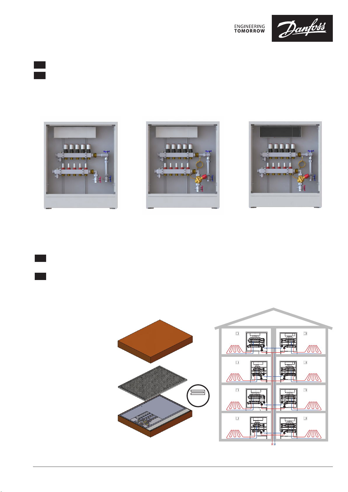
UnoFloor
UnoFloor Basic UnoFloor Comfort UnoFloor Control
Take the prefab for each apartment and put away frame and door which are packed together for
EN
protection. The cardboard box can be used to protect frames and doors during construction phase.
Nehmen Sie die Verteilstation für jede Wohnung und verstauen Sie für spätere Montage den Rahmen und die Tür,
DE
die zum Schutz zusammengepackt sind. Der Karton kann als Schutz für Rahmen und Tür während der Bauphase
verwendet werden.
x4
© Danfoss | 2022.01
AN33345821144001-020104 | 1
Installation Guide / Installationsanleitung UnoFloor
EN
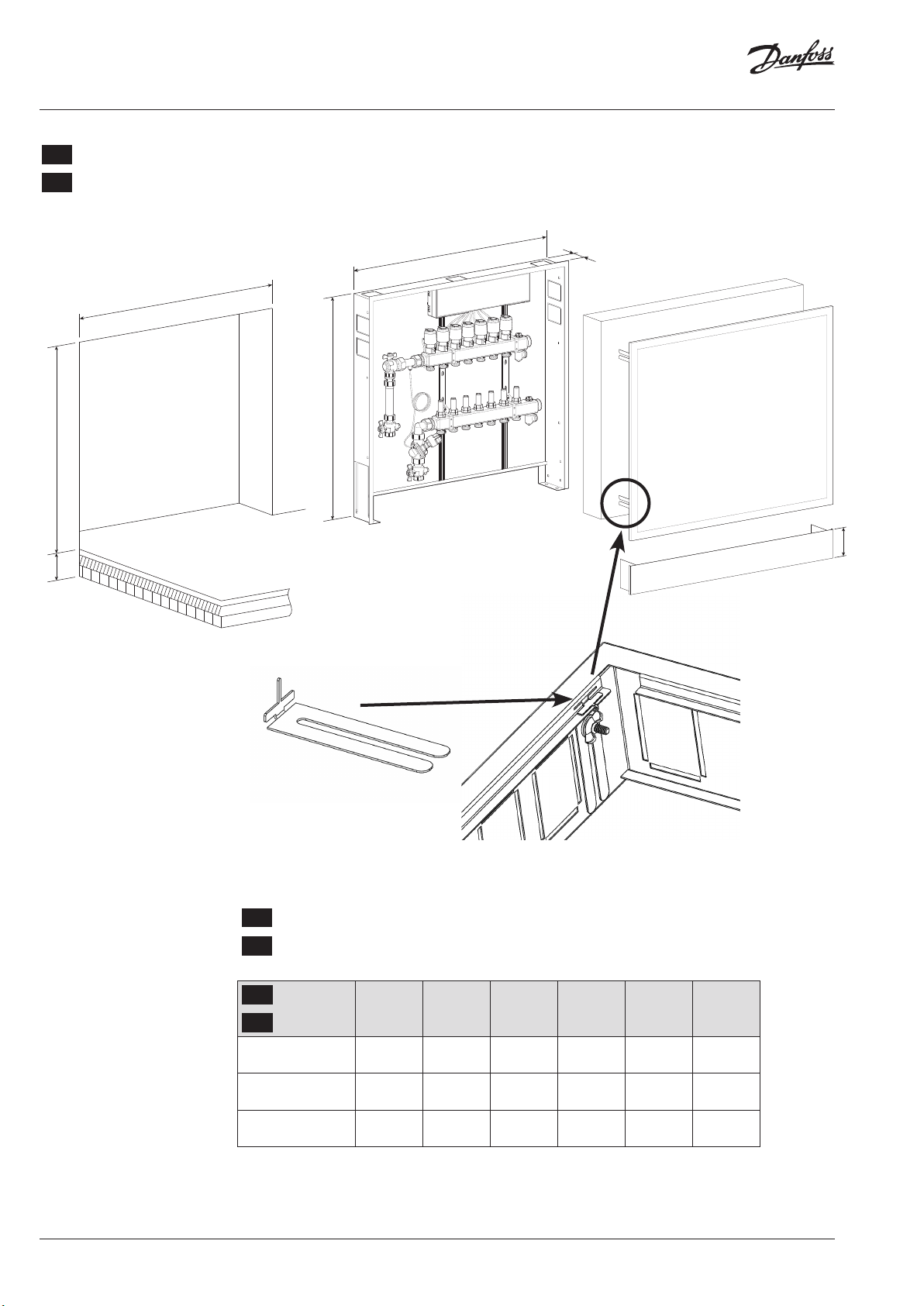
In-wall mounting
DE
Unterputzmontage
A
D
E+F
E
F
C
96
2 | © Danfoss | 2022.01
EN
Keep frame fixing bracket together with the frame and door!
DE
Rahmenhalterung zusammen mit Rahmen und Türe aufbewahren!
EN
Loops
A B C D E F
DE
Kreise
4, 5, 6 610 647 110 617 750 90
7, 8 760 797 110 767 750 90
10, 12 960 997 110 967 750 90
E+F Loops/ Kreise
Min = 750
Max = 840
AN33345821144001-020104

Installation Guide / Installationsanleitung UnoFloor
EN
Preparation and setup
DE
Vorbereitung und Installation
Unbox the cabinet.
Unterputzkasten auspacken
EN
Positioning
DE
Positionierung
Adjust the height. Check the horizontal leveling.
Mit den verstellbaren Füßen in die Waage bringen.
© Danfoss | 2022.01
AN33345821144001-020104 | 3

Installation Guide / Installationsanleitung UnoFloor
EN
Pipe installation
DE
Rohrinstallation
EN
Fill, flush and air
DE
Füllen, spülen und entlüften
Before filling the installation check all connections!
Fill the installation with water acc. to VDI 2035 one loop at a time. Flush
and de-air each loop. Use the flow meters to individually shut off the loops.
Vor dem Füllen sind alle Verbindungen zu überprüfen!
Die Anlage ist mit Heizungswasser gemäß VDI 2035 zu füllen. Das Füllen,
Spülen und Entlüften ist einzeln bei jedem Kreis durchzuführen. Zum
Absperren der einzelnen Kreise kann der jeweilige Durchflussmesser
verwendet werden.
Step 1EN
Schritt 1DE
openEN
offenDE
closeEN
geschlossenDE
EN
Step 1EN
Schritt 1DE
open
offenDE
closeEN
geschlossenDE
barbar
Max 2,5 bar
4 | © Danfoss | 2022.01
AN33345821144001-020104

Installation Guide / Installationsanleitung UnoFloor
EN
Water pressure testing
DE
Füllen, spülen und entlüften
Before filling the installation check all connections!
Fill the installation with water acc. to VDI 2035 one loop at a time. Flush
and de-air each loop. Use the flow meters to individually shut off the loops.
Vor dem Füllen sind alle Verbindungen zu überprüfen!
Die Anlage ist mit Heizungswasser gemäß VDI 2035 zu füllen. Das Füllen,
Spülen und Entlüften ist einzeln bei jedem Kreis durchzuführen. Zum
Absperren der einzelnen Kreise kann der jeweilige Durchflussmesser
verwendet werden.
barbar
2 hours Maximum 2,5 bar
bar
EN
Pressure testing via drain connection
DE
Druckprobe über das Entleerventil
© Danfoss | 2022.01
AN33345821144001-020104 | 5

Installation Guide / Installationsanleitung UnoFloor
EN
Air pressure testing
DE
Druckprobe mit Luft
Follow national standard and safety instructions from EN 14336 Apply 0,5
bar air pressure for approx. 10 minutes and check for leakage. Possible
leakages can be found with leakage spray or applying soap water.
1. All valves must be open.
2. Pressurize installation slowly.
3. Maximum 0,5 bar, keep clear.
4. Keep under pressure for approx. 10 minutes and check for leakage.
Air need to be applied to the system from outside the room of installation.
Befolgen Sie die nationalen Normen und Sicherheitshinweise aus EN
14336. Für 10 Minuten ist ein Druck von ~0,5 bar zu halten und die Anlage
auf Undichtheit zu überprüfen.Um Undichtheiten zu finden kann ein
Lecksuchspray oder Seifenwasser verwendet werden.
1. Alle Ventile öffnen.
2. Druck in der Anlage langsam erhöhen.
3. Max. 0,5 bar verwenden
4. Für 10 Minuten ist der Druck zu halten und die Anlage auf Undichtheit
zu überprüfen.
Die Luft muss von außerhalb des Installationsraumes der Anlage zugeführt
werden.
barbar
10 min. P = 0,5 bar
bar
6 | © Danfoss | 2022.01
AN33345821144001-020104

Installation Guide / Installationsanleitung UnoFloor
EN
Dust cover
DE
Schutzabdeckung
Put on dust cover to protect installation from dust, damage, paint.
Zum Schutz der Installation vor Schmutz und Beschädigung ist die
Schutzabdeckung anzubringen.
© Danfoss | 2022.01
Danfoss Icon™
Thermostat
Kompatibel mit Rahmen aller gängigen Schaltersysteme
Compatible with cover frames of all common systems
Compatible avec les plaques de finition des principaux fabricants
www.icon.danfoss.com
AN33345821144001-020104 | 7

Installation Guide / Installationsanleitung UnoFloor
①② ③
EN
Hydronic balancing and drying screed...
DE
Hydraulischer Abgleich und Estrichtrocknung...
EN
DE
EN
Pre-set LENO manual
balancing valve
Strangregulierventile LENO™
DE
voreinstellen
...without mains power ...with mains power
...ohne Netzstrom ...mit Netzstrom
Click
+
Click
−
Pre-set ASV differential
pressure controller
(basement balancing)
Strangdifferenzdruckregler
ASV voreinstellen
(Strangabgleich)
Pre-set AB-PM differential
pressure controller
(apartment balancing)
Differenzdruckregler mit
Durchflussbegrenzung
AB-PM voreinstellen
(Wohnungsabgleich)
Pre-set AB-PM differential
pressure controller
(apartment balancing)
Differenzdruckregler mit
Durchflussbegrenzung
AB-PM voreinstellen
(Wohnungsabgleich)
Pre-set RA-N built in valve on
EN
SSM-F (apartment balancing)
DE
Voreinstellung der im
SSM-F Verteiler verbauten
RA-N Ventileinsätze
(Wohnungsabgleich)
EN
DE
EN
Very Slow Slow Fast Fast
Sehr langsam Langsam Schnell Schnell
Slow drying of screed
simultaniously
DE
Langsame
Estrichtrochnung
gleichzeitig
Pre-set RA-N built in valve on
SSM-F (apartment balancing)
Voreinstellung der im
SSM-F Verteiler verbauten
RA-N Ventileinsätze
(Wohnungsabgleich)
Avarage time drying screed
simultaniously
Durchschnittliche
Estrichtrocknungszeit
gleichzeitig
Pre-set RA-N built in valve on
SSM-F (apartment balancing)
Voreinstellung der im
SSM-F Verteiler verbauten
RA-N Ventileinsätze
(Wohnungsabgleich)
Fast drying screed
simultaniously
Schnelle
Estrichtrochnung
gleichzeitig
Icon™ automatic balancing,
no pre-setting on manifolds
(Only balancing between
apartments needed!)
Automatischer hydraulischer
Abgleich mit Danfoss Icon™,
keine Voreinstellung der
Verteiler nötig (nur Abgleich
zwischen den Wohnungen
nötig!)
Fast drying screed
simultaniously
Schnelle
Estrichtrochnung
gleichzeitig
8 | © Danfoss | 2022.01
AN33345821144001-020104

Installation Guide / Installationsanleitung UnoFloor
EN
Sizing AB-PM
DE
Dimensionierung
AB-PM
AB-PM is to be sized based on needed flow (Q) and needed differential pressure drop for the
loop (∆pr).
The settings for the manifold can be found at page 5.
Max flow data are presented in the table below.
For any other Q and ∆pr needed, setting can be identified based on Fig. 1.
Die Dimensionierung des AB-PM ist auf Grundlage des erforderlichen Durchflusses (Q) [l/h]
und des für den Verteiler erforderlichen Differenzdruckes zu dimensionieren (∆pr).
Die Voreinstellungen für den Verteiler sind auf Seite 5 dargestellt. Die Werte für den maximalen Durchfluss sind der Tabelle unten dargestellt.
Liegen andere Werte für Q- und ∆pr-Werte vor, lässt sich die Einstellung für AB-PM mithilfe
von Abb. 1 bestimmen.
EN
Typ e
Q max. 600 l/h 915 l /h
Maximum pressure drop avail-
able for system at max flow
Max. pressure at zero load 35 kPa
Start-∆pv (over valve) 8 kPa
DE
Typ
Q max. 600 l/h 915 l /h
Max. verfügbarer Druckabfall im
System bei max. Durchfluss
Oberer Druckgrenzwert des
Druckreglers bei Nulldurchfluss
Start-∆pv (über Ventil) 8 kPa
DN 20 HP
at 100% setting
20 kPa 10 kPa
DN 20 HP bei
Einstellung 100 %
20 kPa 10 kPa
35 kPa
100 %
90 %
80 %
70 %
60 %
50 %
40 %
30 %
20 %
Durchfluss / Flow [l/h]
∆pr [kPa]
Fig. / Abb. 1
DN 20 HP
EN
Loops pre-setting
DE
Voreinstellung der Kreise
Manifold,
EN
with flowmeter
Verteiler
DE
mit Durchflussanzeige
© Danfoss | 2022.01
AN33345821144001-020104 | 9

Installation Guide / Installationsanleitung UnoFloor
EN
Heat up
DE
Aufheizen
If no mains power for heat up period (screed drying) do not remove red mounting split!
Heat up the installation with TWA open, do not remove the retaining ring on the actuator!
Plastic heat meter insert is not for permanent operation! Please exchange in case no heat
meter is mounted!
Wenn zum Aufheizen keine Netzspannung vorhanden ist (Estrichtrocknung), roten Sicherungsring nicht entfernen!
Anlage bei geöffnetem TWA Stellantrieb erwärmen, Sicherungsring am Antrieb nicht entfernen! Wärmezählerpassstück ist nicht für den Dauerbetrieb geeignet! Austauschen, falls
kein Wärmezähler montiert wird!
EN
Danfoss Icon™ Wiring Center 230V
DE
Danfoss Icon™ Klemmleiste 230V
10 | © Danfoss | 2022.01
Please power off the Wiring Center when during
EN
the installation!
Wiring need to done by authorized electrician!
Do not forget the GROUNDING!
Die elektrische Verdrahtung muss bei ausge-
DE
schalteter Spannungsversorgung erfolgen!
Die Verdrahtung darf nur von autorisierten Elektroinstallateuren durchgeführt werden!
Erdung nicht vergessen!
AN33345821144001-020104

Installation Guide / Installationsanleitung UnoFloor
1 1 2 2 3 4 5 6 7 8
987654321 10
1 1 2 2 3 4 5 6 7 8
987654321 10
EN
Connecting room
thermostats
DE
Verdrahtung
Raumthermostate
It is possible to connect up to 8 room thermostats.
Power off the Wiring Center when wiring the thermostats.
Detailed information could be found in the controller installation guide.
Es können bis zu 8 Raumthermostate angeschlossen werden.
Der Regler muss stromlos sein, wärend die Thermostate verdrahten werden.
Detaillierte Informationen finden Sie in der Installationsanleitung des Reglers.
1 1 2 2 3 4 5 6 7 8
987654321 10
EN
Activate
TWA actuators
DE
Aktivierung
TWA Stellantrieb
To activate, remove the red mounting split from TWA’s.
Zum Aktivieren der Stellantriebe, muss die rote Halterung entfernt werden.
1 1 2 2 3 4 5 6 7 8
987654321 10
© Danfoss | 2022.01
AN33345821144001-020104 | 11

Installation Guide / Installationsanleitung UnoFloor
1 1 2 2 3 3 4 5 5 6 7 8
1
987654321 10 11 12
1 5443322 6 7 8
1
987654321 10
1 7654322 8
1
987654321 10 11 12
1 5443322 6 7 8
EN
Actuator wiring
LEFT variant
DE
Verdrahtung Stellantriebe
LINKE Ausführung
The actuators are wired to respective terminals on the Wiring Center as below.
Die Stellantriebe werden wie unten gezeicht an die entsprechenden Klemmen des
Reglers angeschlossen.
987654321 10
1
1 7654322 8
1 1 2 2 3 4 5 6 7 8
987654321 10
12 | © Danfoss | 2022.01
1 1 2 2 3 3 4 5 5 6 7 8
11109754 6 8321 12
AN33345821144001-020104

Installation Guide / Installationsanleitung UnoFloor
EN
Danfoss Icon™ Wiring Center 230V
DE
Danfoss Icon™ Klemmleiste 230V
Option
2
L N
Mains
220 -240 VAC
50/60 Hz
HE AT!
MAX. 100 W
L N
3A
Option
1
2× ≤ 1,5 mm
1 1 2 2 3 3 4 4 5 5 6 6 7 8
THE RMO STAT 1 THE RMO STAT 2 THE RMO STAT 3 TH ERMO STAT 4 TH ERM OSTAT 5 TH ERM OSTAT 6 TH ERM OSTAT 7 TH ERM OSTAT 8
L N
LOAD
SWITCH
EXTERNAL
2× ≤ 1,5 mm
Basic, code no.: 088U1040, 088U1041, 088U1042.
Basic, Bestell-Nr.: 088U1040
5 5 5
L N
≤ 1,5 mm ≤ 1,5 mm ≤ 1,5 mm
L N
LOAD
L N
LOAD
L N
LOAD
L NN
L N
LOAD
Load
L
L N
LOAD
LOAD
L N
LOAD
Options
Load
L N N NTC
L
Example: Icon™ ProgrammableExample: Icon™ DisplayExample: Icon™ Dial
Option
Sensor
Option
3
Option
4
EN
1. 230 VAC output for pump.
2. 230 V Thermal actuator, Normally closed (NC).
DE
1. 230 VAC Ausgang für Pumpe.
2. 230 V thermischer Stellantrieb,
Normal geschlossen (NC).
EN
Wiring details see separate Icon™ 230V instructions
DE
Verdrahtungsdetails siehe separat Anleitung für Icon ™ 230V
© Danfoss | 2022.01
AN33345821144001-020104 | 13

Installation Guide / Installationsanleitung UnoFloor
EN
Danfoss Icon™ Wiring Center 230V
DE
Danfoss Icon™ Klemmleiste 230V
EN
1. Bridge (wire) - allows
use of additional outputs (max. 5 totally per
thermostat)
2. Connect bridge to terminal marked with .
3. Don’t connect a thermostat to the channel
where you took the additional outputs from!
4. You MUST use same
phase on all Wiring
Centers!
DE
1. Verbindungsstück
(Kabel) - ermöglicht
die Verwendung zusätzlicher Ausgänge
(insgesamt max. 5 pro
Thermostat).
2. Verbindungsstück mit
der mit markierten
Klemme verbinden.
3. Verbinden Sie einen
Thermostat niemals mit
dem Kanal, aus dem
Sie die zusätzlichen
Ausgänge entnommen
haben!
4. Sie MÜSSEN an allen
Klemmleisten dieselbe
Phase verwenden!
EN
Max. number of thermostats ............................ 8
Max. number of actuators ..............................14
Supported actuator type ............Normally closed (NC)
Internal fuse ..........................................3 A
Conforms with directives...........LVD, EMC, RoHS, WEEE
Supply voltage...............................220-240 VAC
Supply frequency ................................50/60 Hz
Output voltage, actuators ........................230 VAC
Ambient temp. range, in use ...................0 to +50˚C
Storage temp. range .........................-20 to +60˚C
Output relay, pump .....................230V, max. 100W
Output relay, boiler * ...............Potential free, max. 2A
Outputs, setback & cooling * ...........230V, when active
Input, setback & cooling* ................................
. . . . . . . . . . . . . . . . . . . . . . . . . . . . Ex t. switch input (230V rating)
Rated impulse voltage ...............................4 kV
Temp. for ball pressure test ...........................75˚C
Control polution degree ...............Polution degree 2
Disposal instructions..................As electronic waste
Operating time....................Permanent connection
* only available on featured versions, code no.:
088U1040.
Full data sheet avail able at www.danfoss.com .
Connecting more than 2 actuators to a single thermostat/room
Anschluss von mehr als 2 Antrieben auf einen Raumthermostaten
1 1 2 2 3 4 5 6 7 8
987654321 10
DE
Max. Anzahl Thermostate ..................................8
Max. Anzahl Stellantriebe .................................14
Unterstützter Stellantriebstyp......Normal geschlossen (NC)
Interne Sicherung........................................3 A
Übereinstimmend mit den Richtlinien LVD, EMC, RoHS, WEEE
Versorgungsspannung .........................2 20-240 VAC
Netzfrequenz ...................................... 50/60 Hz
Ausgangsspannung, Stellantriebe...................230 VAC
Umgebungstemperaturbereich, im Einsatz.......0 bis +50˚C
Lagerungstemperaturbereich..................-20 bis +60˚C
Ausgangsrelais, Pumpe ....................230V, Max. 100W
Ausgangsrelais, Kessel* ................Potentialfrei, Max. 2A
Ausgänge Zurückstellung und Kühlung* .....230V (aktiviert)
Eingang Zurückstellung und Kühlung* ......................
. . . . . . . . . . . . . . . . . . . . . . . . . Ext. Schalteingang (230 V Leistung)
Bemessungsstoßspannung .............................4 kV
Temperatur für Kugeldruckprüfung .....................75˚C
Einstellung Verschmutzungsgrad ....Verschmutzungsgrad 2
Hinweise zur Entsorgung...............Als Elektronikschrott
Betriebszeit ........................Permanente Verbindung
* nur verfügbar bei der Version mit Sonderfunktionen,
Best.-Nr.: 088U1040.
Vollständiges Datenblatt unter www.danfoss.com erhältlich
9
10
14 | © Danfoss | 2022.01
AN33345821144001-020104

Installation Guide / Installationsanleitung UnoFloor
© Danfoss | 2022.01
AN33345821144001-020104 | 15

16 | © Danfoss | 2022.01
AN33345821144001-020104
 Loading...