

Page 1
Fact Sheet
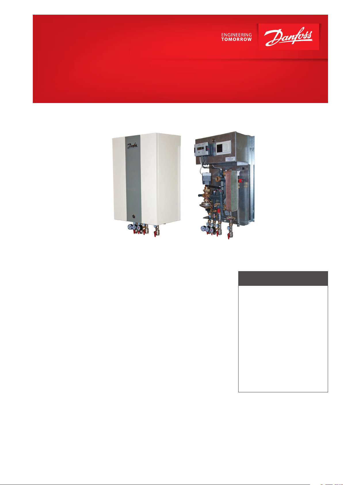
UNISTAT 1016 WR Small
Compact district heating substation from 16 to 30 kW*
Application
The UNISTAT 1016 WR is designed for
use in district heating networks. Depending on type, it can be used both in
micro- and macro-networks, in low temperature (LT) and high temperature (HT)
ranges. The substation is an innovative
product which sets industry standards.
Function
The communicative controller ECL 310 is
used. This controller ensures optimum
regulation of the energy distribution.
The supply temperature for the domestic system is weather compensated.
Energy consumption and temperatures
can be remote monitored.
Construction
The built-in components are connected by means of precisionmanufactured
welded steel pipes. The PN25 version
is featured with welded carbon steel
pipes on primary side and stainless
steel pipes on secondary side. High
quality gaskets are used as sealing
material. The entire water-bearing part
of the substation is thermally insulated
(EPP). This design enables an easy and
quick removal for service purposes.
The benets of this design are:
- Minimal radiation heat losses
- High durability
- Mounting option for pressure
and temperature measuring
instruments is incorporated.
Assembly
The compact substation is easy to wallmount.
FEATURES AND BENEFITS
• Thermal insulation
• Easy installation (by one person)
• Easy electrical connection
- edgewise cable routing
- plenty of space for wiring work
• High serviceability
• Compact and modern design
• Durability due to the use
of precious metals
• PN25 application
• Steel sheet cover
• Danfoss ECL controller
• Easy operation of the controller display
* Power levels and types are dependent
on ow rate and spread
heating.danfoss.com
Page 2
114
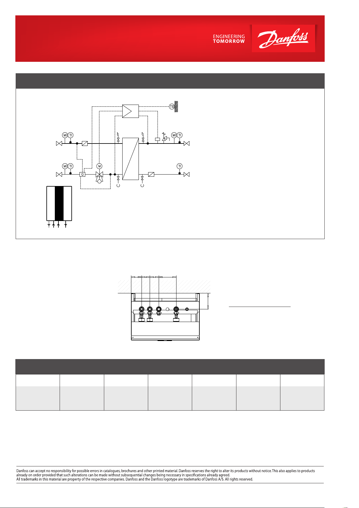
CIRCUIT DIAGRAM – EXAMPLE
3 2
supply
11
4
Primary
3 2
11
Primary
10*
return
B A C D
Technical parameters:
Nominal pressure: PN25
Δ T: 35 oC / 20 oC
Capacity: 16/30 kW
Weight: 40 - 45 kg
Cover: Steel sheet
Dimensions (mm):
With cover (incl. connections):
H 870 × W 490 × D 337
Connections:
A Primary supply
B Primary return
C Secondary return
D Secondary supply
9
1
1 External sensor
2 Thermometer
3 Manometer
4 Sensor
3 2
5 5
7
13
12
11
Secondary
8*
4
supply
5 Air vent
6 Drainage
7 Strainer
8 Safety thermostat
9 Controller
10* Heat meter
2
44
7
11
Secondary
return
14*
1)
6 6
Connection sizes:
Primary: G ¾”
Secondary: Rp ¾”
Heat meter: G ¾” × 110 mm
Regulation possibilities for ECL 310:
• With different application keys
Options*:
11 Ball valve
12 Safety valve
13 Heat exchanger
14* Dierential pressure and ow
controller
• Heat meter
74.5 59
64.5
125
• Safety thermostat
• Actuator with emergency o function
The substation is delivered preassembled, electrically wired internally and tested for function and
leak tightness.
1)
primary side / secondary side
B A C D
Seen from above
STANDARD OPERATING TEMPERATURES*:
Primary
°C
Secondary
°C
* Capacity may vary depending on temperature
Danfoss A/S · 6430 Nordborg · Denmark
Tel.: +45 74 88 22 22 · Fax: +45 74 49 09 49 · danfoss@danfoss.com · www.danfoss.com
© Danfoss | DHS-SRMT/ PL | 2016 . 02
95 - 65 90 - 60
60 - 85
55 - 80
50 - 70
50 - 75
55 - 75
55 - 80
90 - 50 95 - 60 95 - 55
45 - 65
47 - 70
45 - 75
55 - 75
57 - 80
55 - 80
50 - 70
50 - 75
52 - 75
80 - 50
45 - 65
VL.IQ.F2.02
 Loading...