

Page 1
UniLynx Outdoor
User Manual
Benutzerhandbuch
Manuel de l’Utilisateur
Manual del Usario
Manuale dell’Utente
ULX 1800o • ULX 3000o • ULX 3600o • ULX 5400o
MAKING MODERN LIVING POSSIBLE
SOLAR INVERTERS
Page 2

Choice of Language - Sprachauswahl - Choix de la langue Selección de idioma - Scelta della lingua
Page 2
English UK
Seite 13
Deutsch
Page 25
Français
Página 37
Español
Pagina 49
Italiano
L00410362-05_2q 1
Page 3

Contents
1. Introduction
3
Introduction 3
2. Function Description
4
Definition of Operation Modes 4
PV Configuration 4
LEDs 6
Display 6
Overview Menu Section A 6
Overview Menu Section B 7
3. Troubleshooting
10
Troubleshooting 10
Inverter Event Messages 10
4. Maintenance
12
Maintenance 12
Cleaning the Cabinet 12
Cleaning the Heatsink 12
Contents
2 L00410362-05_2q
Page 4
1. Introduction
1.1. Introduction
This manual describes Danfoss photovoltaic inverters. These products are among the most technologically advanced and efficient inverters on the market and are designed to supply the owner
with reliable solar energy for many years.
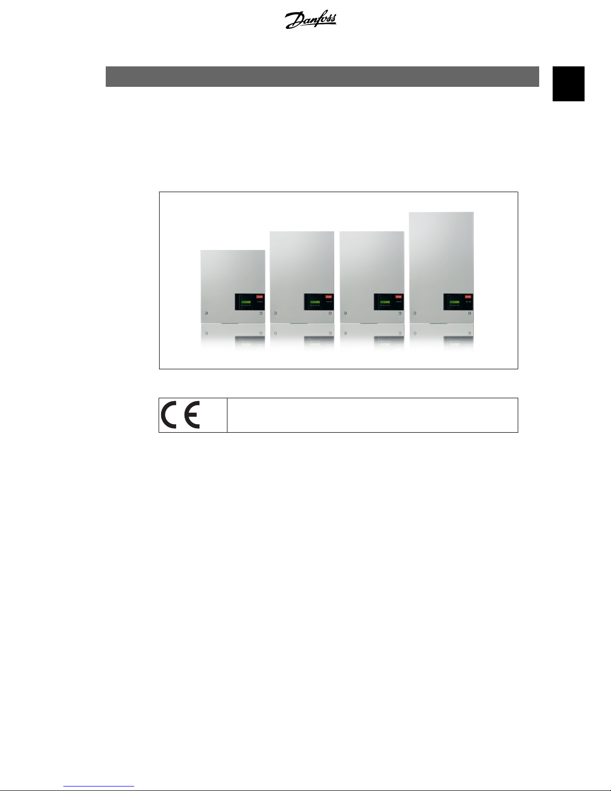
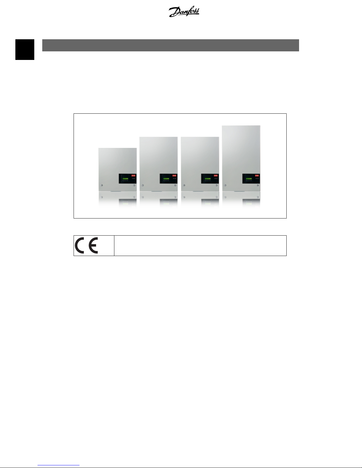
Illustration 1.1: ULX Outdoor Inverter with Display
CE marking - This certifies the conformity of the equipment with the regulations which apply in accordance with the directives 2004/108/EC and 2006/95/
EC.
1. Introduction
L00410362-05_2q 3
1
Page 5

2. Function Description
2.1. Definition of Operation Modes
The inverter has four modes:
Standby mode:
In standby mode, the inverter is ready to switch into connecting mode. As decision variable the
input voltage of the PV generator is used. If the input voltage exceeds a preset nominal value,
the inverter shifts from “standby” to “connecting”, or continues into the operation mode “OFF” if
the PV voltage drops.
Connecting mode:
After performing the system tests, which check whether all connection conditions are met, the
inverter goes from standby mode to connecting mode. During the specified cut-in time, the inverter continues testing the system values and connects the inverter to the grid if the system tests
are okay. The minimum cut-in time is specified by the supplier and authorities and can vary from
region to region.
Grid mode:
In this mode, the inverter is connected to the grid and supplies power to the grid. The inverter is
only uncoupled from the grid in case of abnormal grid conditions or when PV power is not available.
PV configuration mode
Having completed the connecting mode the PV module wiring is automatically tested to detect
whether any of the DC inputs are wired in parallel string configuration. If so, the DC modules are
automatically run in parallel string configuration mode (Master/Slave).
Derating temperature
If the display shows (DRT. TEMP), the inverter is derating due to high temperatures.
Derating grid
If the display shows (DRT GRID), the inverter is derating due to high voltage on the grid.
Off:
If there is no PV power available, the inverter waits ten minutes (specified value) before it disengages. In this mode, the power supply to all processors is switched off to conserve energy. This
is the normal night mode.
2.1.1. Grid Surveillance
In order to safeguard the people working on AC power lines and the inverter, the inverter shuts
down in the event of abnormal grid conditions or failures. The inverter continuously monitors grid
voltage and frequency by means of an internal control circuit. Subsequently, the inverter will reconnect as soon as the grid is within limits.
2.1.2. PV Configuration
Upon connecting to grid an automatic test of the PV module wiring is performed by the inverter.
This test is made in order to determine the wiring configuration of the modules. It is established
whether the modules are connected in individual string configuration or in parallel string configuration and the inverter is automatically configured accordingly.
2. Function Description
4 L00410362-05_2q
2
Page 6
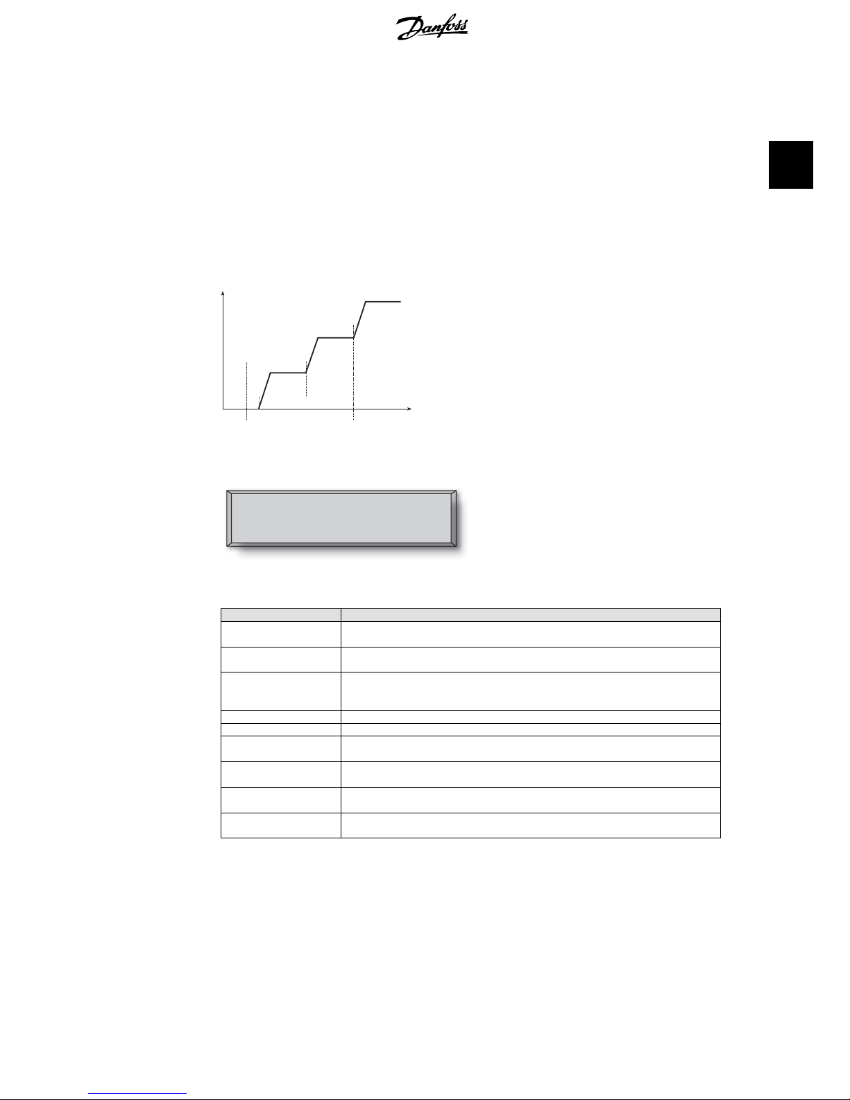
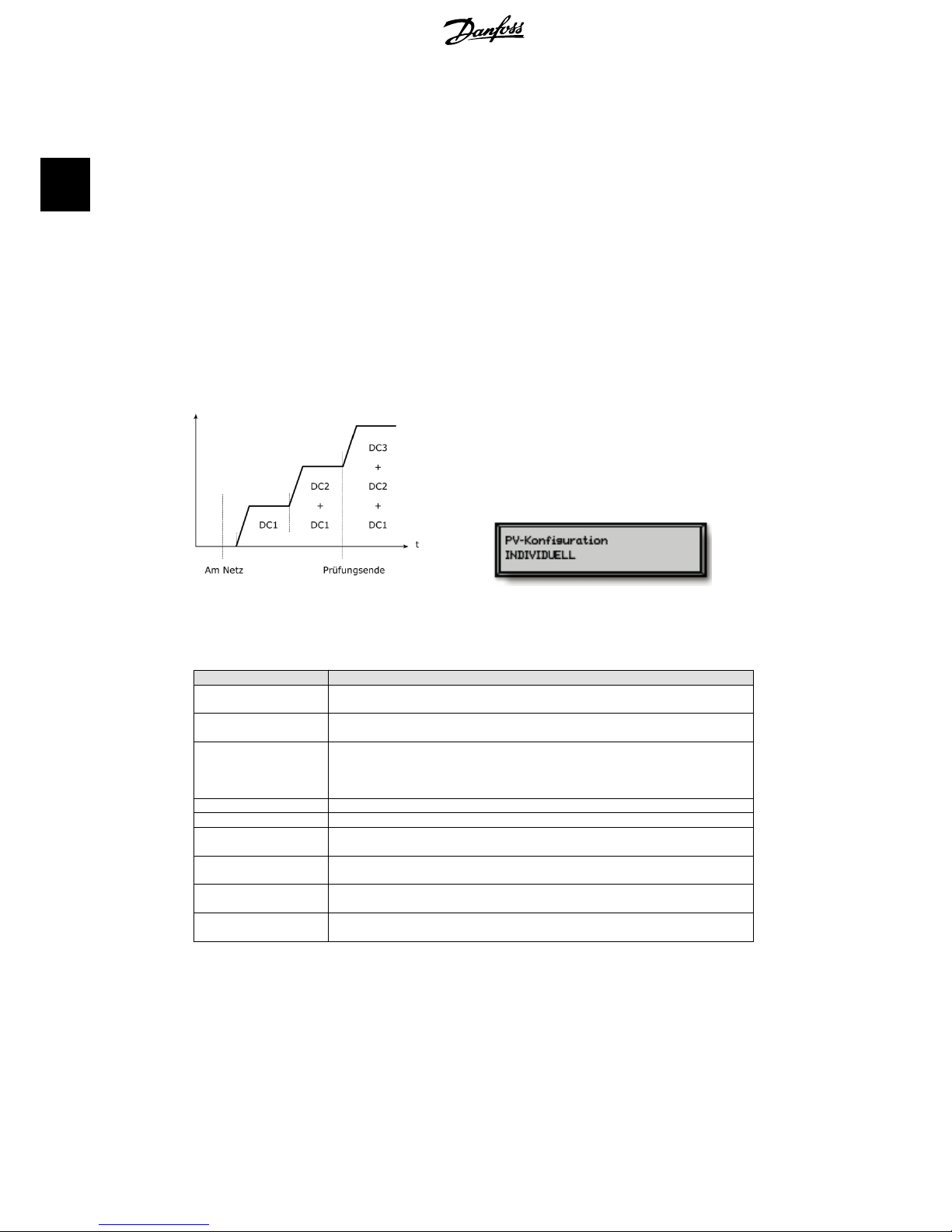
The test works by activating the input one by one. The test takes 1-2 minutes and the inverter
continues to produce energy meanwhile. In menu B the result of the test can be read in the display
menu called PV configuration.
Upon test completion the display will automatically show the PV configuration detected; however,
only if the buttons on the display have not been used in the past 3 minutes.
For ULX 5400o, 2 out of 3 DC modules must be powered for the test to run. If not enough PV
power is available to power 2 modules, the test is postponed until sufficient PV power is available
for the second DC module to run.
Notice that the inverter continues to produce energy in the meantime.
DC3
+
DC2 DC2
+ +
DC1 DC1 DC1
t
On Grid Test end
Illustration 2.1: PV configuration test
The display readout shows the status of the
test. The first line shows that this concerns the
PV configuration and the second line shows
which status the test is in or which configuration it has detected.
PV configuration
INDIVIDUAL
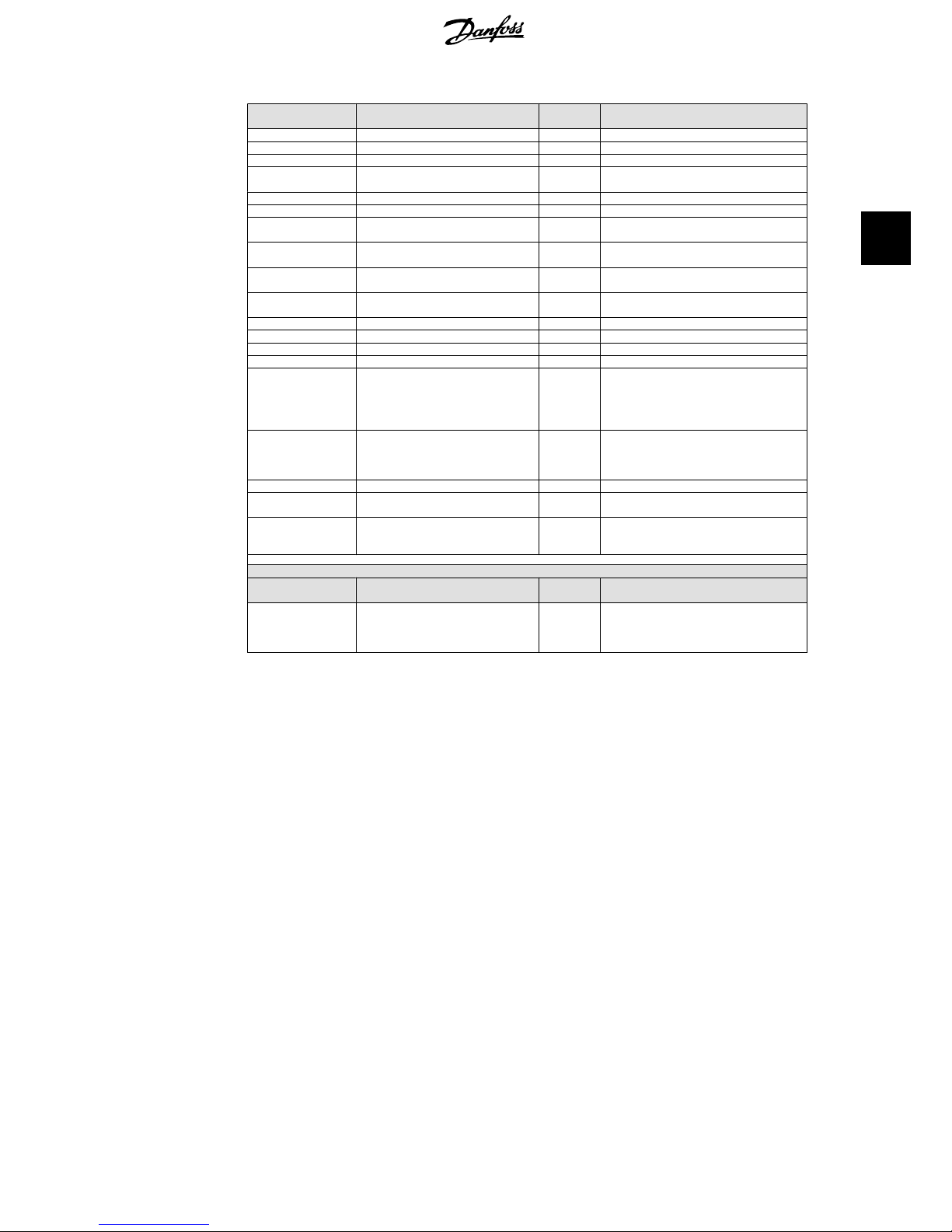
The status field may show the following:
Display Text Description
IDLE PV configuration test has not yet been run. Shown before the inverter connects to
grid.
OFF PV configuration test is disabled. Applicable to ULX 1800o and to inverters where
the test is otherwise disabled.
WAITING The PV configuration test is ready to run, but only solar radiation for one PV input
is available. (Applicable to ULX 5400o). The inverter can only determine the con-
figuration of all three modules, when two are running.
PV-AUTODETECTING The PV configuration test is running. No result yet.
INDIVIDUAL The PV modules are connected in individual string configuration
PARALLEL 1-2* The PV configuration has ended, concluding that inputs 1 and 2 are connected in
parallel string configuration.
PARALLEL 1-3* The PV configuration has ended, concluding that inputs 1 and 3 are connected in
parallel string configuration.
PARALLEL 2-3* The PV configuration has ended, concluding that inputs 2 and 3 are connected in
parallel string configuration.
PARALLEL 1-2-3 The PV configuration has ended, concluding that inputs 1, 2 and 3 are connected
in parallel string configuration.
Table 2.1: PV Configuration Test Status Field Text
*) The “PARALLEL 1-2” is only allowed for the ULX 3000o / 3600o inverter. The “PARALLEL 1-2”,
“PARALLEL 1-3”, and “PARALLEL 2-3” is not allowed for the ULX 5400o inverter.
2. Function Description
L00410362-05_2q 5
2
Page 7
2.1.3. LEDs
The green LED indicators show the production in percentage of the nominal inverter power rating.
The leftmost green LED is always lit when the inverter is connected to the grid. While connecting
to grid both the red LED and the leftmost green LED will be on. When the inverter is off grid, the
red LED to the left is lit to indicate that the inverter is in standby mode. No green LEDs are lit. If
no LED’s are on the inverter is off. If the inverter is forced into standby mode because of an event
in the inverter or the peripheral connections, e.g. disconnection from the grid, the red LED starts
flashing.
For a description of events, please refer to the section on
Troubleshooting
.
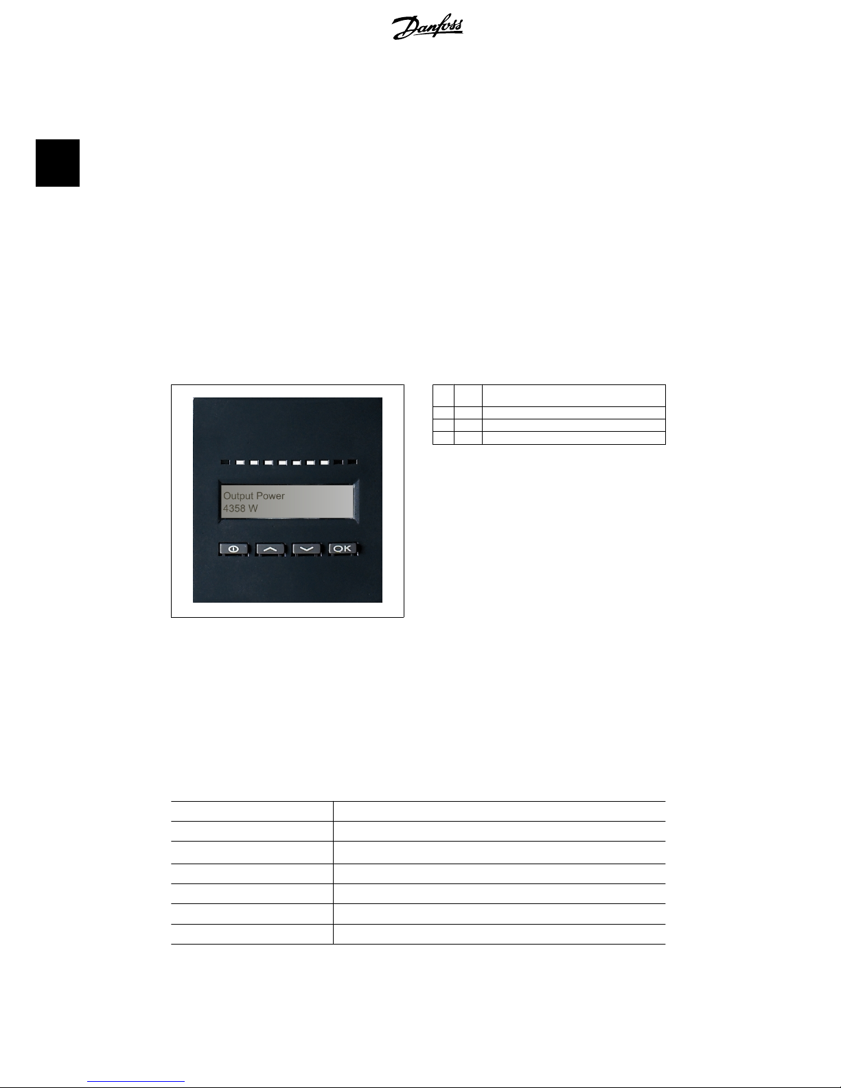
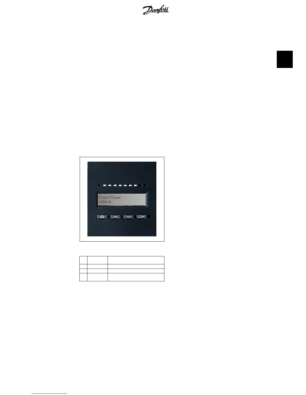
2.1.4. Display
Through the integrated display on the inverter front, the user has access to all information about
the PV system and the inverter. When the inverter is in OFF mode (at night), the inverter can be
activated by pressing the left button (ESC).
Illustration 2.2: Display
θ
ESC Goes one step backwards/up in the menu
structure
▲
Up Scrolls back to the previous menu display
▼
Down Scrolls forward to the next menu display
OK
Enter New menu level or changing of settings
The parameters shown in the display refer to
internally measured voltages and currents.
The parameters shown may deviate.
The display information is organised in a menu
structure divided into two sections: A and B
Section A: Contains information about the inverter and PV system performance.
Section B: Displays all measurement values
and user settings.
2.1.5. Overview Menu Section A
The table below gives an overview of the menu structure. The values shown are only intended as
examples of display texts. The display text (shown in the first column Display Functions ) is divided
between 2 lines, with 16 characters available per line. The line division is illustrated with the symbol
|.
Menu Structure A
Display Functions Description
Output power | 0 W Current output power in watt.
Inverter name |
Use Service Tool to enter inverter name. If the inverter name is undefined this menu
is skipped.
Total production | 22.991 kWh Total energy production in kWh since first inverter start-up.
Total operating time | 00028h 57m 02s Total operating time (time with power on) displayed in hours, minutes and seconds.
Production today | 19637 Wh Energy production today in Wh.
Go to menu B Jumps to menu level B when OK is pressed.
Table 2.2: Overview Menu Structure A
2. Function Description
6 L00410362-05_2q
2
Page 8
2.1.6. Overview Menu Section B
The table below gives an overview of the menu structure. The two menu levels are clearly indicated
by an arrow followed by a submenu. The values shown are only intended as examples of display
texts.
The display text (shown in the first column Display Functions ) is divided between 2 lines, with 16
characters available per line. The line division is illustrated with the symbol |.
Menu Structure B
Display Functions Description
Operation mode | STANDBY
Displays present inverter operation mode. See operation mode definitions
in chapter 2.
PV configuration | IDLE
Shows the status of the automatic PV configuration test and the results
found.
Event: Mod. | ENS FL. CH DCAC
If the inverter is not connected to the grid because of a failure, the red
LED starts flashing, and the reason for the failure is shown here.
Language | ENGLISH View and choose display language. Does not affect any other settings.
Grid voltage | 0 V Displays the present grid AC voltage.
Grid current | 0.00 A Displays the present current flow to the grid.
Grid frequency | 0.00 Hz Displays the present grid frequency.
Grid impedance | 0.0 ohm Displays the present grid impedance.
PV voltage | Press OK to view Press OK to access submenu for recorded values.
↳
Submenu
PV voltage no. 1 | 303.0 V Present voltage at PV input 1 (upper position in inverter).
PV voltage no. 2 | 303.0 V Present voltage at PV input 2 (second position in inverter)*.
PV voltage no. 3 | 303.0 V Present voltage at PV input 3 (third position in inverter)*.
PV current | PRESS OK to view Press OK to access submenu for recorded values.
↳
Submenu
PV current no. 1 | 0.0 A Present current at PV input 1 (upper position in inverter).
PV current no. 2 | 0.0 A Present current at PV input 2 (second position in inverter)*.
PV current no. 3 | 0.0 A Present current at PV input 3 (third position in inverter)*.
Maximum values | Press OK to view Press OK to access submenu for recorded values.
↳
Submenu
AC out: 1844 W | 8.356 A 263 V
Maximum values recorded at AC output since last resetting of max. value
memory.
DC1 in: 2220 W** | 8.004 A 509 V
Maximum values recorded at DC1 input since last resetting of max. value
memory.
DC2 in: 2220 W** | 8.004 A 509 V
Maximum values recorded at DC2* input since last resetting of max. value
memory.
DC3 in: 2220 W** | 8.004 A 509 V
Maximum values recorded at DC3* input since last resetting of max. value
memory.
Table 2.3: Overview Menu Structure B
*) The PV2 and PV3 menus are only displayed in inverters equipped with two or three inputs.
2. Function Description
L00410362-05_2q 7
2
Page 9
Menu Structure B- Continued
Display Functions Description
Maximum values | Press OK to view Press OK to access submenu for recorded values.
↳
Submenu
AC out: 1844 W | 8.356 A 263 V
Maximum values recorded at AC output since last resetting of max. value
memory.
DC1 in: 2220 W** | 8.004 A 509 V
Maximum values recorded at DC1 input since last resetting of max. value
memory.
DC2 in: 2220 W** | 8.004 A 509 V
Maximum values recorded at DC2* input since last resetting of max. value
memory.
DC3 in: 2220 W** | 8.004 A 509 V
Maximum values recorded at DC3* input since last resetting of max. value
memory.
Total drt. Temp. - Press OK to view
Total Derating Temperature. Shows the total amount of time the inverter
has derated due to high temperature.
↳
Submenu
DC1 derate temp. | 3h 35m
DC1 Derating Temperature. Shows the amount of time the inverter has
derated due to high temperature.
DC2 derate temp. | 3h 35m
DC2* Derating Temperature. Shows the amount of time the inverter has
derated due to high temperature.
DC3 derate temp. | 3h 35m
DC3* Derating Temperature. Shows the amount of time the inverter has
derated due to high temperature.
Total drt. Grid | 0h 00 min
Total Derating Grid. Shows the amount of time the inverter has derated
due to unstable grid conditions.
Power-down time | 00600 seconds
Time before inverter goes into ‘OFF’ mode when no solar power is available.
Code numbers | PRESS OK to view Press OK to access submenu for recorded values.
↳
Submenu
Inverter code no. | Indicates inverter product code.
AC code number | C0070105602 Indicates AC module product code.
DC1 code number | C0070105402 Indicates DC1 module product code.
DC2 code number | C0070105402 Indicates DC2* module product code.
DC3 code number | C0070105402 Indicates DC3* module product code.
Serial numbers | Press OK to view Press OK to go to submenu for recorded values.
↳
Submenu
Inverter SN: | Indicates inverter serial number.
AC SN: | 117500C0408 Indicates AC module serial number.
DC1 SN: | 642800C0808 Indicates DC1 module serial number.
DC2 SN: | 642800C0808 Indicates DC2* module serial number.
DC3 SN: | 642800C0808 Indicates DC3* module serial number.
Table 2.4: Overview Menu Structure B
*) The DC2 and DC3 menus are only displayed in inverters equipped with two or three inputs.
**) The maximum values for PV power may reach more than 2000 W in inverters where the inputs are connected in parallel.
This is normal.
In menu section A the display will continue to show the menu point last chosen by the user.
In menu B the display automatically switches to menu A when there has been no keyboard activity
for 3 minutes.
2. Function Description
8 L00410362-05_2q
2
Page 10

If the inverter is off grid and no keys have been pressed for a certain number of seconds, the
display will automatically switch to the operation mode display.
If the inverter is on grid and there has been no keyboard activity for 3 minutes, the display automatically switches to the display Production today. When the PV configuration test initiates and
terminates the display temporarily changes to menu B to show the state of the PV configuration
test.
If the inverter is disconnected from the grid because of a failure, the red LED will start flashing,
and the display automatically switches to menu B, where the event is shown.
If an earthing fault occurs, the display will indicate this by a flash of the lit green LEDs. The display
will change to “current event”, if it has not been operated in the past 10 minutes. The inverter
will continue to produce energy. In case an earth fault occurs, this does not indicate an inverter
error and technical assistance must be called to check the PV panel connection.
Only applicable if earth fault detection is enabled. By default, earth fault detection is enabled for
the following countries: Austria, France and Spain.
2. Function Description
L00410362-05_2q 9
2
Page 11
3. Troubleshooting
3.1. Troubleshooting
Note:
Remember that only trained and authorised personnel familiar with electrical systems and
safety issues may work on inverters and electrical installations.
In the following, the term 'Event' describes all events that prevent the inverter from operating
properly.
An event may occur anywhere in the installation (grid, PV module, cable and connections, inverter)
at any time. Not all events indicate an inverter error.
If the PV system does not supply power to the grid as expected, please go through the following
checklist:
1. Check that the grid is connected properly to the inverter and that the grid is ready for
operation.
2. Check that there is sufficient solar radiation to generate power.
3. Check for shading and loose cables/connections in the PV system.
4. Check the installation of the PV modules if the voltages of the PV modules is not within
the expected values.
5. Check the event in menu B. If the red LED is flashing, this indicates a failure.
6. If the above-mentioned points are OK, wait 15 minutes to find out whether there is a
permanent failure.
7. If the PV system still does not supply any power to the grid, please check the voltage,
current and power of the PV module as well as voltage, current and power of the grid in
menu B.
8. If the voltage values of the grid do not lie within the threshold values, please contact
your public utility for technical assistance.
3.1.1. Inverter Event Messages
Event: Mod.
U-GRID DCAC
The red LED will start flashing in case of an
inverter event. Please check the event in
menu B.
The event text is a short text describing the event. If the inverter reports an event ID number to
the display instead of a text, no event text has been predefined for that particular event ID number. This could be the case if the display software is older than the inverter software. Module
designation identifies the module that caused the event (DC1, DC2, DC3 or AC).
3. Troubleshooting
10 L00410362-05_2q
3
Page 12
Event text Description Fault
origin
Action in the event of a permanent fail-
ure
U 3.3 Internal power supply outside limits Inverter Service inverter
U 5.0 Internal power supply outside limits Inverter Service inverter
U 15.0 Internal power supply outside limits Inverter Service inverter
U PV Input voltage from PV string too high PV system Request technical service from PV system
supplier
U-SNUBBER Snubber voltage too high Inverter Service inverter
U DC-BUS DC bus voltage too high Inverter Service inverter
U-GRID AC grid voltage outside the threshold
values (higher or lower than setting)
AC grid In case of repeated occurrence: Request
technical service from utility
F-GRID Grid frequency outside limits (outside
settings)
AC grid In case of repeated occurrence: Request
technical service from utility
IPM CURRENT The DC content in the AC current is too
high
Inverter Service inverter
ENS ENS error AC grid In case of repeated occurrence: Request
technical service from utility
ENS RAM ENS memory error Inverter Service inverter
ENS FL. CHKSM Flash memory error after self-test Inverter Service inverter
ENS EP. CHKSM EPROM memory error after self-test Inverter Service inverter
HW TRIP Hardware trip – current too high Inverter Service inverter
TEMP HIGH Temperature in integrated power mod-
ule too high
Environment
Check whether inverter is covered.
Check inverter for free air flow through heat
sink. Clean heat sink.
Check that ambient temperature is within
limits.
EPRM PAR. LIM Validity check of grid voltage and fre-
quency settings. Settings too far away
from actual grid voltage and frequency
values.
Inverter Request service to check inverter settings
ENS COM ERR Error in communication with ENS board Inverter Service inverter
ENS impedance Grid impedance step higher than limit AC grid In case of repeated occurrence: Request
technical service from utility
PV—CONFIG—ERR Error detected by PV configuration test PV system Check the cabling of the PV panels. Two DC
inputs are wired in parallel string configura-
tion, one is not
Not recorded in the event log - red LED does not flash
Event text Description Fault
origin
Action in the event of a permanent fail-
ure
EARTHFAULT Current event shown in grid mode PV system Earth fault, check PV system for earthing to
avoid damage to PV panels. Request techni-
cal service from the PV system supplier or in-
staller.
Table 3.1: Inverter Event Log
A “permanent failure” is defined by an event having been present for more than 15 minutes.
3. Troubleshooting
L00410362-05_2q 11
3
Page 13
4. Maintenance
4.1. Maintenance
Normally, the ULX outdoor inverters need no maintenance or calibration. It should be ensured,
however, that the cooling is not obstructed.
To ensure the functionality of the DC-switch, all switches should be switched on and off (by turning
the switch to on and off positions ten times), once a year, to clean the contacts.
4.1.1. Cleaning the Cabinet
Clean inverter by means of pressurised air or a soft cloth or a brush. Do not use a water hose,
aggressive chemicals, cleaning solvents or strong detergents to clean the inverter.
4.1.2. Cleaning the Heatsink
In order to secure proper function and long inverter life, it is essential that the free air circulation
around the heatsink at the back of the inverter and by the fan at the bottom of the inverter is not
obstructed. If the free air circulation is obstructed, e.g. by dust or snow, this has to be removed.
Clean the heatsink by means of pressurised air or a soft cloth or a brush. Do not use a water hose,
aggressive chemicals, cleaning solvents or strong detergents to clean the inverter.
The heatsink can reach a temperature of more than 70°C during operation. Touching
components of this temperature may result in serious injuries!
Note:
Do not cover the inverter.
4. Maintenance
12 L00410362-05_2q
4
Page 14

Inhaltsverzeichnis
1. Einführung
14
Einführung 14
2. Funktionsbeschreibung
15
Definition der Betriebsarten 15
PV-Konfiguration 16
LEDs 17
Display 17
Überblick Menübereich A 18
Überblick Menübereich B 19
3. Fehlerbehebung
22
Fehlerbehebung 22
Wechselrichter – Ereignismeldungen 22
4. Wartung
24
Wartung 24
Reinigen des Schaltschranks 24
Reinigen des Kühlkörpers 24
Inhaltsverzeichnis
L00410362-05_2q 13
Page 15
1. Einführung
1.1. Einführung
Dieses Handbuch beschreibt die photovoltaischen Wechselrichter von Danfoss. Diese Produkte
zählen zu den technologisch fortschrittlichsten und effizientesten Wechselrichtern auf dem Markt
und ermöglichen eine verlässliche Versorgung mit Solarenergie über viele Jahre hinweg.
Abbildung 1.1: ULX-Wechselrichter für den Außenbereich – mit Display
CE-Kennzeichnung: Diese Kennzeichnung gibt an, dass die Geräte den geltenden Vorschriften der Richtlinien 2004/108/EG und 2006/95/EG entsprechen.
1. Einführung
14 L00410362-05_2q
1
Page 16

2. Funktionsbeschreibung
2.1. Definition der Betriebsarten
Der Wechselrichter hat vier Betriebsarten:
Standby-Modus:
Im Standby-Modus ist der Wechselrichter bereit, auf den Anschlussmodus umzuschalten. Als Entscheidungsgröße wird die Eingangsspannung des PV-Generators herangezogen. Übersteigt die
Eingangsspannung einen definierten Sollwert, wechselt der Wechselrichter aus der Betriebsart
Standby in den Anschlussmodus oder leitet bei Verringerung der PV-Spannung in die Betriebsart
„AUS“ über.
Anschlussmodus:
Nach Durchführung der Systemprüfungen, bei denen geprüft wird, ob alle Anschlussbedingungen
erfüllt sind, geht der Wechselrichter vom Standby-Modus in den Anschlussmodus über. Der Wechselrichter fährt während der vorgegebenen Aufschaltzeit mit der Prüfung der Systemwerte fort
und verbindet, soweit die Systemprüfungen erfolgreich sind, den Wechselrichter mit dem Netz.
Die minimale Aufschaltzeit ist von den Versorgungsunternehmen und Behörden vorgegeben und
kann von Region zu Region unterschiedlich sein.
Netzbetrieb:
Bei dieser Betriebsart ist der Wechselrichter mit dem Netz verbunden und liefert Strom ins Netz.
Der Wechselrichter wird nur bei einer abnormalen Netzbedingung oder bei fehlender PV-Leistung
vom Netz abgekoppelt.
PV-Konfigurationsbetrieb
Nach Beendigung des Anschlussmodus wird die PV-Modulverdrahtung automatisch geprüft, um
zu erkennen, ob alle DC-Eingänge in Parallelstrangkonfiguration verdrahtet sind. Ist dies der Fall,
werden die DC-Module automatisch im Parallelstrangkonfigurationsbetrieb ausgeführt (Master/
Slave ).
Temperaturminderung
Wenn das Display die Meldung (Temp.mind.) anzeigt, wird der Wechselrichter aufgrund von hohen
Temperaturen gedrosselt.
Leistungsreduzierung wegen Spannung
Wenn das Display die Meldung (Spann. mind.) anzeigt, wird der Wechselrichter aufgrund von
hoher Netzspannung gedrosselt.
Aus:
Ist kein PV-Strom vorhanden, wartet der Wechselrichter zehn Minuten (vorgegebener Wert), bevor er abschaltet. In dieser Betriebsart ist die Stromversorgung zu allen Prozessoren abgeschaltet,
um Strom zu sparen. Das ist der normale Nachtbetrieb.
2.1.1. Netzüberwachung
Um an Leistungskabeln arbeitendes Personal und den Wechselrichter zu schützen, schaltet der
Wechselrichter bei abnormalem Netzverhalten oder Netzausfall ab. Der Wechselrichter überwacht
über einen internen Prüfstrang ständig die Netzspannung und -frequenz. Daher stellt der Wechselrichter die Verbindung wieder her, wenn sich die Netzwerte wieder innerhalb der Grenzwerte
befinden.
2. Funktionsbeschreibung
L00410362-05_2q 15
2
Page 17
2.1.2. PV-Konfiguration
Bei Anschluss an das Netz führt der Wechselrichter eine automatische Prüfung der PV-Modulverdrahtung durch. Diese Prüfung bestimmt die Verkabelungskonfiguration der Module. Es wird
ermittelt, ob die Module in Einzelstrangkonfiguration oder Parallelstrangkonfiguration angeschlossen sind, und der Wechselrichter wird automatisch entsprechend konfiguriert. Die Prüfung aktiviert nacheinander jeden Eingang. Sie nimmt 1 - 2 Minuten in Anspruch, und der Wechselrichter
erzeugt dabei weiterhin Energie. In Menü B kann das Prüfergebnis im Displaymenü für die PVKonfiguration abgelesen werden. Nach Abschluss der Prüfung zeigt das Display automatisch die
erkannte PV-Konfiguration, allerdings nur, wenn die Tasten am Display in den letzten drei Minuten
nicht betätigt wurden.
Bei ULX 5400o müssen zwei von drei DC-Modulen für den Test mit Strom versorgt werden. Steht
nicht genügend PV-Energie zur Versorgung von zwei Modulen zur Verfügung, wird die Prüfung
verschoben, bis genügend PV-Energie für den Betrieb des zweiten DC-Moduls vorliegt.
Dabei erzeugt der Wechselrichter weiterhin Energie.
Abbildung 2.1: PV-Konfigurationsprüfung
Die Displayanzeige zeigt den Prüfstatus. Die
erste Zeile zeigt, dass dies die PV-Konfiguration betrifft, und die zweite Zeile zeigt den
Status der Prüfung oder die erkannte Konfiguration.
Das Statusfeld kann Folgendes zeigen:
Angezeigter Text Beschreibung
LEERLAUF Die PV-Konfigurationsprüfung wurde noch nicht ausgeführt. Dies wird vor dem
Anschluss des Wechselrichters an das Netz gezeigt.
AUS PV-Konfigurationsprüfung deaktiviert. Gilt für ULX 1800o sowie für Wechselrichter,
bei denen die Prüfung auf andere Weise deaktiviert wurde.
WARTEN Die PV-Konfigurationsprüfung ist betriebsbereit, es ist jedoch nur genügend Ein-
strahlung für einen PV-Eingang verfügbar. (Gültig für ULX 5400o). Der Wechselrichter kann nur die Konfiguration aller drei Module bestimmen, wenn zwei von
ihnen laufen.
PV-AUTOERKENNUNG Der PV-Konfigurationstest wird ausgeführt. Es liegt jedoch noch kein Ergebnis vor.
INDIVIDUELL Die PV-Module sind in Einzelstrangkonfiguration angeschlossen.
PARALLEL 1-2* Die PV-Konfiguration ist beendet und hat ergeben, dass die Eingänge 1 und 2 in
Parallelstrangkonfiguration angeschlossen sind.
PARALLEL 1-3* Die PV-Konfiguration ist beendet und hat ergeben, dass die Eingänge 1 und 3 in
Parallelstrangkonfiguration angeschlossen sind.
PARALLEL 2-3* Die PV-Konfiguration ist beendet und hat ergeben, dass die Eingänge 2 und 3 in
Parallelstrangkonfiguration angeschlossen sind.
PARALLEL 1-2-3 Die PV-Konfiguration ist beendet und hat ergeben, dass die Eingänge 1, 2 und 3
in Parallelstrangkonfiguration angeschlossen sind.
Tabelle 2.1: Text im Statusfeld zur PV-Konfigurationsprüfung
*) „PARALLEL 1-2“ ist nur für den Wechselrichter ULX 3000o / 3600o zulässig. „PARALLEL 1-2“,
„PARALLEL 1-3“ und „PARALLEL 2-3“ ist nicht beim Wechselrichter ULX 5400o zulässig.
2. Funktionsbeschreibung
16 L00410362-05_2q
2
Page 18
2.1.3. LEDs
Die grünen LED-Anzeigen geben die Produktion in Prozent der Nennleistung des Wechselrichters
an.
Die ganz links befindliche grüne LED leuchtet immer auf, wenn der Wechselrichter mit dem Netz
verbunden ist. Bei Netzanschaltung leuchten sowohl die rote LED als auch die grüne LED ganz
links. Wenn der Wechselrichter vom Netz getrennt ist, leuchtet die rote LED links auf, um anzuzeigen, dass sich der Wechselrichter im Standby-Modus befindet. Es leuchten keine grünen LEDs.
Wenn keine LEDs leuchten, ist der Wechselrichter ausgeschaltet. Befindet sich der Wechselrichter
aufgrund eines Ereignisses im Wechselrichter oder der peripheren Anschlüsse, z. B. einem Netzabwurf, zwangsweise im Standby-Modus, beginnt die rote LED zu blinken.
Eine Beschreibung der Ereignisse enthält der Abschnitt
Fehlersuche und -behebung
.
2.1.4. Display
Der Benutzer hat über das integrierte Display auf der Vorderseite des Wechselrichters Zugang zu
allen Informationen über das PV-System und den Wechselrichter. Befindet sich der Wechselrichter
im OFF-Betrieb (bei Nacht), ist es möglich, den Wechselrichter durch eine Betätigung der linken
Taste (ESC-Taste) am Display zu aktivieren.
Abbildung 2.2: Display
θ
ESC Einen Schritt zurück/nach oben in der
Menüstruktur
▲
Nach oben Blättert zum vorherigen Menü
▼
Nach unten Blättert zum nächsten Menü
OK
Eingabetaste Neue Menüebene oder Änderung der
Einstellungen
Die angezeigten Parameter im Display beziehen sich auf intern gemessene Spannungen
und Ströme. Die angezeigten Parameter können Abweichungen aufweisen.
Die Display-Informationen sind in einer in zwei
Bereiche unterteilten Menüstruktur organisiert: A und B
Abschnitt A: Enthält Informationen über die
Wechselrichter- und PV-Systemleistung.
Abschnitt B: Zeigt alle Messwerte und Benutzereinstellungen an.
2. Funktionsbeschreibung
L00410362-05_2q 17
2
Page 19
2.1.5. Überblick Menübereich A
Die nachfolgende Tabelle bietet einen Überblick der Menüstruktur. Die angegebenen Werte dienen
nur als Beispiel für die Displaytexte. Der Displaytext (siehe erste Spalte Displayfunktionen) wird
auf zwei Zeilen à 16 Zeichen angezeigt. Der Zeilenumbruch ist durch das Symbol | gekennzeichnet.
Menüstruktur A
Displayfunktionen Beschreibung
Ausgangsleistung | 0 W Aktuelle Ausgangsleistung in Watt.
Wechselr. Name
Verwenden Sie das Service Tool zur Eingabe des Wechselrichternamens. Wenn der Name
des Wechselrichters nicht definiert ist, wird dieses Menü übersprungen.
Energie gesamt | 22.991 kWh Gesamte Energieerzeugung in kWh seit Start des Wechselrichters.
Betriebsdauer | 00028h 57m 02s
Die Gesamtbetriebsdauer (Zeit der Stromeinspeisung) wird in Stunden, Minuten und Sekunden angezeigt.
Energie heute | 19637 Wh Energieerzeugung von heute in Wh.
Menü B wählen Springt nach Betätigung von OK zu Menüebene B.
Tabelle 2.2: Überblick Menüstruktur A
2. Funktionsbeschreibung
18 L00410362-05_2q
2
Page 20

2.1.6. Überblick Menübereich B
Die nachfolgende Tabelle bietet einen Überblick der Menüstruktur. Die beiden Menüebenen werden durch einen Pfeil gekennzeichnet, dem ein Untermenü folgt. Die angegebenen Werte dienen
nur als Beispiel für die Displaytexte.
Der Displaytext (siehe erste Spalte Displayfunktionen) wird auf zwei Zeilen à 16 Zeichen angezeigt.
Der Zeilenumbruch ist durch das Symbol | gekennzeichnet.
Menüstruktur B
Displayfunktionen Beschreibung
Betriebsart | STANDBY
Zeigt die aktuelle Betriebsart des Wechselrichters an. Siehe Definitionen der
Betriebsarten in Kapitel 2.
PV-Konfiguration | LEERLAUF
Zeigt den Status der automatischen PV-Konfigurationsprüfung und ermittelte
Ergebnisse an.
Event Modul | ENS FL. CH DCAC
Ist der Wechselrichter aufgrund einer Störung nicht am Netz angeschlossen,
blinkt die rote LED, und die Störungsursache wird hier angezeigt.
Sprache | DEUTSCH
Anzeige und Auswahl der Displaysprache. Hat keinen Einfluss auf andere
Einstellungen.
Netzspannung | 0 V Zeigt die aktuelle AC-Netzspannung an.
Netzstrom | 0.00 A Zeigt den aktuell in das Netz fließenden Strom an.
Netzfrequenz | 0.00 Hz Zeigt die aktuelle Netzfrequenz an.
Netzimpedanz | 0.0 ohm Zeigt die aktuelle Netzimpedanz an.
PV Spannung | OK drücken
Die Taste „OK“ drücken, um zum Untermenü für protokollierte Werte zu gelangen.
↳
Untermenü
PV Spannung Nr. 1 | 303.0 V Aktuelle Spannung am PV-Eingang 1 (obere Position im Wechselrichter).
PV Spannung Nr. 2 | 303.0 V Aktuelle Spannung am PV-Eingang 2 (zweite Position im Wechselrichter)*.
PV Spannung Nr. 3 | 303.0 V Aktuelle Spannung am PV-Eingang 3 (dritte Position im Wechselrichter)*.
PV Strom | OK drücken
Die Taste „OK“ drücken, um zum Untermenü für protokollierte Werte zu gelangen.
↳
Untermenü
PV Strom Nr. 1 | 0.0 A Aktueller Strom am PV-Eingang 1 (obere Position im Wechselrichter).
PV Strom Nr. 2 | 0.0 A Aktueller Strom am PV-Eingang 2 (zweite Position im Wechselrichter)*.
PV Strom Nr. 3 | 0.0 A Aktueller Strom am PV-Eingang 3 (dritte Position im Wechselrichter)*.
Maximalwerte │ OK drücken
Die Taste „OK“ drücken, um zum Untermenü für protokollierte Werte zu gelangen.
↳
Untermenü
AC: 1844 W | 8.356 A 263 V
Maximalwerte gemessen am AC-Ausgang seit der letzten Rückstellung des
Maximalwertspeichers.
DC1: 2220 W** | 8.004 A 509 V
Maximalwerte gemessen am DC1-Eingang seit der letzten Rückstellung des
Maximalwertspeichers.
DC2: 2220 W** | 8.004 A 509 V
Maximalwerte gemessen am DC2-Eingang** seit der letzten Rückstellung
des Maximalwertspeichers.
DC3: 2220 W** | 8.004 A 509 V
Maximalwerte gemessen am DC3-Eingang* seit der letzten Rückstellung des
Maximalwertspeichers.
Tabelle 2.3: Überblick Menüstruktur B
*) Die PV2- und PV3-Menüs kommen nur in mit zwei oder drei Eingängen ausgestatteten Wechselrichtern zur Anzeige.
2. Funktionsbeschreibung
L00410362-05_2q 19
2
Page 21

Menüstruktur B – Fortsetzung
Displayfunktionen Beschreibung
Maximalwerte | OK drücken
Die Taste „OK“ drücken, um zum Untermenü für protokollierte Werte zu gelangen.
↳
Untermenü
AC: 1844 W | 8.356 A 263 V
Maximalwerte gemessen am AC-Ausgang seit der letzten Rückstellung des
Maximalwertspeichers.
DC1: 2220 W** | 8.004 A 509 V
Maximalwerte gemessen am DC1-Eingang seit der letzten Rückstellung des
Maximalwertspeichers.
DC2: 2220 W** | 8.004 A 509 V
Maximalwerte gemessen am DC2-Eingang** seit der letzten Rückstellung
des Maximalwertspeichers.
DC3: 2220 W** | 8.004 A 509 V
Maximalwerte gemessen am DC3-Eingang* seit der letzten Rückstellung des
Maximalwertspeichers.
Temp mind gesamt | OK drücken
Temperaturminderung insgesamt. Zeigt den Gesamtwert des Zeitraums an,
über den der Wechselrichter aufgrund von hohen Temperaturen gedrosselt
wurde.
↳
Untermenü
DC1 Temp. mind. | 3h 35m
Temperaturminderung DC1. Zeigt den Zeitraum an, über den der Wechselrichter aufgrund von hohen Temperaturen gedrosselt wurde.
DC2 Temp. mind. | 3h 35m
Temperaturminderung DC2*. Zeigt den Zeitraum an, über den der Wechselrichter aufgrund von hohen Temperaturen gedrosselt wurde.
DC3 Temp. mind. | 3h 35m
Temperaturminderung DC3*. Zeigt den Zeitraum an, über den der Wechselrichter aufgrund von hohen Temperaturen gedrosselt wurde.
Temp mind gesamt | 0h 00m
Netzleistungsreduzierung gesamt. Zeigt den Gesamtwert des Zeitraums an,
über den der Wechselrichter aufgrund von instabilen Netzbedingungen gedrosselt wurde.
Abschaltzeit | 600 Sekunden
Zeit bevor der Wechselrichter in den OFF-Betrieb übergeht, wenn kein Solarstrom verfügbar ist.
Produktnummern | OK drücken
Die Taste „OK“ drücken, um zum Untermenü für protokollierte Werte zu gelangen.
↳
Untermenü
Wechselrichter Nr. Zeigt den Produktcode des Wechselrichters an.
AC Nummer | C0070105602 Zeigt den Produktcode des AC-Moduls an.
DC1 Nummer | C0070105402 Zeigt den Produktcode des DC1-Moduls an.
DC2 Nummer | C0070105402 Zeigt den Produktcode des DC2*-Moduls an.
DC3 Nummer | C0070105402 Zeigt den Produktcode des DC3*-Moduls an.
Seriennummern | OK drücken
Die Taste „OK“ drücken, um zum Untermenü für protokollierte Werte zu gelangen.
↳
Untermenü
Wechselrichter SN: | Zeigt die Seriennummer des Wechselrichters an.
AC SN: | 117500C0408 Zeigt die Seriennummer des AC-Moduls an.
DC1 SN: | 642800C0808 Zeigt die Seriennummer des DC1-Moduls an.
DC2 SN: | 642800C0808 Zeigt die Seriennummer des DC2*-Moduls an.
DC3 SN: | 642800C0808 Zeigt die Seriennummer des DC3*-Moduls an.
Tabelle 2.4: Überblick Menüstruktur B
*) Die DC2- und DC3-Menüs kommen nur in mit zwei oder drei Eingängen ausgestatteten Wechselrichtern zur Anzeige.
**) Die Maximalwerte für PV-Leistung können mehr als 2000 W erreichen, wenn die Eingänge parallel verbunden sind. Dies
ist normal.
Wird in Menü B die Tastatur mehr als 3 Minuten nicht betätigt, kehrt das Display automatisch zu
Menü A zurück.
2. Funktionsbeschreibung
20 L00410362-05_2q
2
Page 22

Ist der Wechselrichter vom Netz getrennt, und wurden im Menü B drei Minuten lang keine Tasten
betätigt, springt das Display automatisch zum Menü A.
Ist der Wechselrichter am Netz, und wurde einige Sekunden lang keine Taste betätigt, schaltet
das Display automatisch auf das Schirmbild „Betriebsart“.
Ist der Wechselrichter am Netz, und wurde drei Minuten lang keine Taste betätigt, schaltet das
Display automatisch auf das Schirmbild „Energie heute“. Zu Beginn und Ende der PV-Konfigurationsprüfung wechselt das Display kurz auf Menü B, um den Status der PV-Konfigurationsprüfung
zu zeigen.
Wurde der Wechselrichter aufgrund eines Fehlers vom Netz getrennt, beginnt die rote LED zu
blinken, und die Anzeige wechselt automatisch in das Menü B, in dem das Ereignis angezeigt wird.
Tritt ein Erdungsfehler auf, wird dieser am Display durch Blinken der grünen LEDs angezeigt. Die
Anzeige wechselt zu „Aktuelles Ereignis“, wenn in den letzten zehn Minuten keine Aktualisierung
erfolgt ist. Der Wechselrichter erzeugt weiterhin Strom. Im Falle eines Erdungsfehlers weist dies
nicht auf einen Wechselrichterfehler hin, und die Verbindung des PV-Paneels muss mithilfe der
technischen Unterstützung geprüft werden.
Dies gilt nur, wenn die Erdungsfehlererkennung aktiviert ist. Diese ist werkseitig für folgende
Länder aktiviert: Österreich, Frankreich und Spanien.
2. Funktionsbeschreibung
L00410362-05_2q 21
2
Page 23

3. Fehlerbehebung
3.1. Fehlerbehebung
Anmerkung:
Beachten Sie, dass alle Arbeiten an Wechselrichtern und elektrischen Installationen nur von
geschultem und autorisiertem, mit elektrischen Anlagen und Sicherheitsfragen vertrautem Personal vorgenommen werden dürfen.
Im Folgenden beschreibt der Ausdruck „Ereignis“ alle Ereignisse, die den Wechselrichter daran
hindern, ordnungsgemäß zu arbeiten.
Ein Ereignis kann an jeder Stelle (Netz, PV-Module, Kabel und Verbindungen, Wechselrichter) der
Installation auftreten. Nicht jedes Ereignis zeigt eine Fehlfunktion des Wechselrichters an.
Falls das PV-System nicht wie erwartet Strom in das Netz liefert, arbeiten Sie die folgende Checkliste ab:
1. Überprüfen Sie, ob das Netz ordnungsgemäß an den Wechselrichter angeschlossen und
betriebsbereit ist.
2. Überprüfen Sie, ob genügend Sonneneinstrahlung zur Stromerzeugung zur Verfügung
steht.
3. Überprüfen Sie das PV-System auf Verschattung und lose Kabel bzw. Verbindungen.
4. Falls die Spannungen der PV-Module außerhalb der zu erwartenden Werte liegen, überprüfen Sie die Installation der PV-Module.
5. Prüfen Sie das Ereignis in Menü B. Blinkt die rote LED, weist dies auf einen Fehler hin.
6. Falls die obigen Punkte in Ordnung waren, warten Sie 15 Minuten, um festzustellen, ob
es sich um eine permanente Störung handelt.
7. Liefert die PV-Anlage noch immer keinen Strom in das Netz, überprüfen Sie die Spannung, den Strom und die Leistung des PV-Moduls sowie die Spannung, den Strom und
die Leistung des Netzes in Menü B.
8. Liegen die Spannungen des Netzes nicht innerhalb der Grenzwerte, wenden Sie sich an
Ihr Energieversorgungsunternehmen, um technische Hilfe zu erhalten.
3.1.1. Wechselrichter – Ereignismeldungen
Event: Mod.
U-GRID DCAC
Die rote LED beginnt zu blinken, wenn ein
Wechselrichterereignis vorliegt. Prüfen Sie
das Ereignis in Menü B.
Der Ereignistext ist ein das Ereignis beschreibender Kurztext. Übermittelt der Wechselrichter eine
Ereignis-Kennnummer anstatt eines Texts an das Display, ist für diese Ereignis-Kennnummer kein
vordefinierter Ereignistext vorhanden. Dieser Fall kann auftreten, wenn die Display-Software älter
ist als die Wechselrichter-Software. Die Modulbezeichnung identifiziert das Modul, das das Ereignis
hervorgerufen hat (DC1, DC2, DC3 oder AC).
3. Fehlerbehebung
22 L00410362-05_2q
3
Page 24

Ereignistext Beschreibung Fehler-
ursache
Maßnahme bei einem dauerhaften Fehler
U 3,3 Interne Stromversorgung außerhalb
der Grenzwerte
Wechselrichter
Den Wechselrichter warten
U 5,0 Interne Stromversorgung außerhalb
der Grenzwerte
Wechselrichter
Den Wechselrichter warten
U 15,0 Interne Stromversorgung außerhalb
der Grenzwerte
Wechselrichter
Den Wechselrichter warten
U PV Eingangsspannung von PV-String zu
hoch
PV-System Technische Unterstützung vom Lieferanten
des PV-Systems anfordern
U-SNUBBER Snubber-Spannung zu hoch Wechsel-
richter
Den Wechselrichter warten
U DC-Bus DC-Busspannung zu hoch Wechsel-
richter
Den Wechselrichter warten
U-NETZ AC-Netzspannung außerhalb der Grenz-
werte (höher oder niedriger als Einstellung)
AC-Netz Bei wiederholtem Auftreten: Technische Un-
terstützung des Energieversorgers anfordern
F-NETZ Netzfrequenz außerhalb der Grenzwer-
te (außerhalb der Einstellungen)
AC-Netz Bei wiederholtem Auftreten: Technische Un-
terstützung des Energieversorgers anfordern
IPM-STROM Der Gleichstromanteil im Wechselstrom
ist zu hoch.
Wechselrichter
Den Wechselrichter warten
ENS ENS-Fehler AC-Netz Bei wiederholtem Auftreten: Technische Un-
terstützung des Energieversorgers anfordern
ENS-RAM ENS-Speicherfehler Wechsel-
richter
Den Wechselrichter warten
ENS FL. CHKSM Flash-Speicherfehler nach Selbsttest Wechsel-
richter
Den Wechselrichter warten
ENS EP. CHKSM EPROM-Speicherfehler nach Selbsttest Wechsel-
richter
Den Wechselrichter warten
HW-AUSL. Hardware-Auslösung – Stromstärke zu
hoch
Wechselrichter
Den Wechselrichter warten
TEMP HOCH Temperatur im integrierten Netzteil zu
hoch
Umgebung Prüfen, ob der Wechselrichter abgedeckt ist.
Prüfen, ob die Luft ungehindert um den Kühlkörper des Wechselrichters zirkulieren kann.
Den Kühlkörper reinigen.
Prüfen, ob die Umgebungstemperatur innerhalb der Grenzwerte liegt.
EPRM PAR. LIM Gültigkeitsprüfung von Netzspannung
und Frequenzeinstellungen. Einstellungen unterscheiden sich zu sehr von den
tatsächlichen Werten für Netzspannung
und Frequenz.
Wechselrichter
Unterstützung zur Prüfung der Wechselrichtereinstellungen anfordern
ENS KOMM.-FEHL Fehler bei der Kommunikation mit der
ENS-Platine
Wechselrichter
Den Wechselrichter warten
ENS-Impedanz Netzimpedanzschritt höher als Grenz-
wert
AC-Netz Bei wiederholtem Auftreten: Technische Un-
terstützung des Energieversorgers anfordern
PV—KONFIG—FEHL Beim PV-Konfigurationstest wurde ein
Fehler erkannt.
PV-System Verkabelung der PV-Paneele prüfen. Zwei
DC-Eingänge sind in paralleler String-Konfiguration verkabelt, der andere nicht.
Nicht im Ereignisprotokoll enthalten – rote LED blinkt nicht
Ereignistext Beschreibung Fehler-
ursache
Maßnahme bei einem dauerhaften Fehler
ERDUNGSFEHLER Aktuelles Ereignis im Netzmodus PV-System Erdungsfehler, prüfen Sie die Erdung des PV-
Systems, um Schäden an den PV-Paneelen
zu vermeiden. Technische Unterstützung
vom Lieferanten des PV-Systems oder des
Installateurs anfordern
Tabelle 3.1: Wechselrichter - Ereignisprotokoll
Ein „dauerhafter Fehler“ liegt vor, wenn ein Ereignis länger als 15 Minuten auftritt.
3. Fehlerbehebung
L00410362-05_2q 23
3
Page 25

4. Wartung
4.1. Wartung
Die ULX Wechselrichter für den Außenbereich erfordern im Normalfall keine Wartung oder Kalibrierung. Es ist nur auf eine unbehinderte Kühlung zu achten.
Um die Funktionalität des DC-Schalters sicherzustellen, müssen einmal jährlich alle Schalter ausund eingeschaltet werden (hierzu den Schalter zehnmal ein- und ausschalten), um die Kontakte
zu reinigen.
4.1.1. Reinigen des Schaltschranks
Reinigen Sie den Wechselrichter mit einem weichen Tuch. Verwenden Sie zum Reinigen keine
aggressiven Chemikalien, Reinigungslösungen oder kräftige Waschmittel.
4.1.2. Reinigen des Kühlkörpers
Um eine ordnungsgemäße Funktion und lange Lebensdauer des Wechselrichters zu gewährleisten,
darf die freie Luftzirkulation um den Kühlkörper auf der Rückseite des Wechselrichters und durch
den Lüfter am Boden nicht behindert werden. Wird die Luftzirkulation behindert (z. B. durch Staub
oder Schnee), muss das Hindernis beseitigt werden. Reinigen Sie den Kühlkörper mit Druckluft,
einem weichen Tuch oder einer Bürste. Verwenden Sie zum Reinigen des Wechselrichters keinen
Wasserschlauch, keine aggressiven Chemikalien, Reinigungslösungen oder kräftige Waschmittel.
Der Kühlkörper kann während des Betriebs Temperaturen von über 70°C erreichen.
Die Berührung von Bauteilen unter diesen Betriebszuständen kann zu ernsthaften
Verletzungen führen!
Anmerkung:
Den Wechselrichter nicht abdecken.
4. Wartung
24 L00410362-05_2q
4
Page 26

Table des matières
1. Introduction
26
Introduction 26
2. Description de fonction
27
Définition des modes de fonctionnement 27
Configuration PV 28
LED 29
Écran 29
Présentation de la section A du menu 30
Présentation de la section B du menu 31
3. Dépannage
34
Dépannage 34
Messages d'événements de l'onduleur 34
4. Maintenance
36
Maintenance 36
Nettoyage de l’armoire 36
Nettoyage du dissipateur de chaleur 36
Table des matières
L00410362-05_2q 25
Page 27

1. Introduction
1.1. Introduction
Ce manuel décrit des onduleurs photovoltaïques Danfoss. Ces produits comptent parmi les onduleurs les plus efficaces et sophistiqués du marché. Leur conception assure pendant de longues
années à leur propriétaire une alimentation en énergie solaire fiable.
Illustration 1.1: Onduleur extérieur ULX avec écran
Marquage CE : ce marquage certifie la conformité de l'équipement aux règlements en vigueur, conformément aux directives 2004/108/CE et 2006/95/CE.
1. Introduction
26 L00410362-05_2q
1
Page 28

2. Description de fonction
2.1. Définition des modes de fonctionnement
L'onduleur dispose de quatre modes :
Mode Veille :
En mode Veille, l'onduleur est prêt à basculer en mode Connexion. La tension d'entrée du générateur PV constitue la variable déterminante. Si la tension d'entrée excède une valeur nominale
préréglée, l'onduleur passe du mode Veille au mode Connexion ou continue à fonctionner en mode
de fonctionnement OFF si la tension PV chute.
Mode Connexion :
Après les tests du système, qui vérifient si toutes les conditions de connexion sont satisfaites,
l'onduleur bascule du mode Veille au mode Connexion. Au cours du temps de commutation spécifié, l'onduleur continue à tester les valeurs du système, puis se connecte au réseau si les tests
sont concluants. Le temps de commutation minimal est défini par le fournisseur et les autorités.
Il peut varier d'une région à une autre.
Mode Réseau :
Dans ce mode, l'onduleur est raccordé au réseau et l'alimente. L'onduleur est découplé du réseau
uniquement en cas de conditions de réseau anormales ou lorsqu'aucune puissance PV n'est disponible.
Mode de configuration PV
Une fois le mode Connexion établi, le câblage du module PV est automatiquement testé afin de
détecter si l'une des entrées CC est câblée dans une configuration de branches parallèles. Si tel
est le cas, les modules CC fonctionneront en mode de configuration de branches parallèles
(Master/Slave ).
Réduction température
Si l'écran affiche (RÉDUC. TEMP.), la valeur nominale de l'onduleur est réduite suite à une température trop importante.
Réduction tension
Si l'écran affiche (RÉDUC. PUISS.), la valeur nominale de l'onduleur est réduite suite à une tension
trop importante sur le réseau.
Arrêt :
Si aucune puissance PV n'est disponible, l'onduleur patiente 10 minutes (valeur spécifiée) avant
de se désengager. Dans ce mode, l'alimentation de l'ensemble des processeurs est coupée afin
de conserver l'énergie. Il s'agit du mode nocturne normal.
2.1.1. Surveillance du réseau
Afin d'assurer la protection des personnes travaillant sur des lignes électriques CA et sur l'onduleur,
celui-ci s'arrête en cas de conditions de réseau anormales ou de pannes. L'onduleur surveille en
permanence la tension et la fréquence du réseau à l'aide d'un circuit de contrôle interne. L'onduleur se reconnecte ultérieurement dès que le réseau revient au sein des limites.
2. Description de fonction
L00410362-05_2q 27
2
Page 29

2.1.2. Configuration PV
Lors du raccordement au réseau, un test automatique du câblage du module PV est effectué par
l'onduleur. Ce test est réalisé pour déterminer la configuration de câblage des modules. Il détecte
si les modules sont connectés dans une configuration de branches individuelles ou parallèles, et
l'onduleur est automatiquement paramétré en fonction de cette configuration.
Le test s'effectue en activant une à une les entrées. Cela prend 1 à 2 minutes et l'onduleur continue
à produire de l'énergie pendant ce temps. Le résultat du test s'affiche dans le menu B sous l'affichage Configuration PV.
À la fin du test, l'écran indique automatiquement la configuration PV détectée, mais uniquement
si les boutons de l'écran n'ont pas été utilisés au cours des 3 dernières minutes.
Pour un onduleur ULX 5400o, 2 modules CC sur 3 doivent être mis sous tension pour pouvoir
exécuter le test. En l'absence de puissance PV suffisante pour alimenter 2 modules, le test est
reporté jusqu'à l'obtention de la puissance suffisante pour pouvoir faire fonctionner le deuxième
module CC.
Noter cependant que pendant ce temps l'onduleur continue à produire de l'énergie.
DC3
+
DC2 DC2
+ +
DC1 DC1 DC1
t
On Grid Test end
Illustration 2.1: Test de la configuration PV
L'écran indique l'état du test. La première ligne mentionne la configuration PV et la seconde l'état du test ou la configuration détectée.
2. Description de fonction
28 L00410362-05_2q
2
Page 30

Le champ relatif à l'état peut préciser les points suivants :
Affichage Description
DISPO Le test de la configuration PV n'a pas encore été exécuté. S'affiche avant le rac-
cordement de l'onduleur au réseau.
OFF Le test de la configuration PV est désactivé. Applicable aux onduleurs ULX 1800o
et aux onduleurs où le test est désactivé.
ATTENTE Le test de la configuration PV est prêt à être exécuté, mais le rayonnement solaire
n'est disponible que pour une seule entrée PV. (Applicable aux onduleurs ULX
5400o.) L'onduleur peut déterminer la configuration des trois modules uniquement
lorsque deux fonctionnent.
AUTODETECTION PV Le test de la configuration PV est en cours. Aucun résultat pour le moment.
INDIVIDUEL Les modules PV sont connectés dans une configuration de branches individuelles.
PARALLEL 1-2* La configuration PV est terminée. Conclusion : les entrées 1 et 2 sont connectées
dans une configuration de branches parallèles.
PARALLEL 1-3* La configuration PV est terminée. Conclusion : les entrées 1 et 3 sont connectées
dans une configuration de branches parallèles.
PARALLEL 2-3* La configuration PV est terminée. Conclusion : les entrées 2 et 3 sont connectées
dans une configuration de branches parallèles.
PARALLEL 1-2-3 La configuration PV est terminée. Conclusion : les entrées 1, 2 et 3 sont connectées
dans une configuration de branches parallèles.
Tableau 2.1: Message du champ relatif à l'état du test de la configuration PV
*) La configuration PARALLEL 1-2 n'est permise que pour l'onduleur ULX 3000o / 3600o. Les
configurations PARALLEL 1-2, PARALLEL 1-3 et PARALLEL 2-3 ne sont pas permises pour l'onduleur ULX 5400o.
2.1.3. LED
Les LED vertes indiquent la production en pourcentage de la puissance nominale de l'onduleur.
La LED verte la plus à gauche reste allumée en permanence lorsque l'onduleur est raccordé au
réseau. Lors de la connexion au réseau, la LED rouge et la LED verte la plus à gauche sont allumées. La LED rouge à gauche est allumée lorsque l'onduleur se trouve en mode Veille et n'est pas
raccordé au réseau. Aucune LED verte n'est allumée. Si aucune LED n'est allumée, l'onduleur est
éteint. Si l'onduleur est activé en mode Veille de force suite à un événement au niveau des connexions de l'onduleur ou des périphériques (déconnexion du réseau, p. ex.), la LED rouge commence à clignoter.
Se reporter à la description des événements dans la section
Dépannage
.
2.1.4. Écran
Grâce à l'écran intégré à l'avant de l'onduleur, l'utilisateur peut accéder à toutes les informations
relatives au système PV et à l'onduleur. Si l'onduleur se trouve en mode OFF (la nuit), il peut
cependant être activé en appuyant sur le bouton gauche (ESC).
2. Description de fonction
L00410362-05_2q 29
2
Page 31

Illustration 2.2: Écran
θ
Echap Revient en arrière ou remonte d'un niveau
dans la structure de menu.
▲
Up Défile jusqu'à l'affichage de menu précé-
dent.
▼
Bas Défile jusqu'à l'affichage de menu suivant.
OK
Entrée Nouveau niveau de menu ou modification
des réglages
Les paramètres affichés à l'écran font référence à des tensions et courants mesurés en interne. Les paramètres indiqués peuvent varier.
Les informations d'affichage sont organisées
dans une structure de menu divisée en deux
sections : A et B.
Section A : Contient des informations sur les
performances de l'onduleur et du système PV.
Section B : Affiche toutes les valeurs de mesure et les réglages de l'utilisateur.
2.1.5. Présentation de la section A du menu
Le tableau ci-dessous fournit un aperçu de la structure de menu. Les valeurs indiquées ne sont
données qu'à titre d'exemple pour l'affichage de texte. Le texte affiché (voir la première colonne
Fonctions d'affichage) est divisé en 2 lignes, avec 16 caractères disponibles par ligne. La division
en lignes est illustrée par le symbole |.
Structure du menu A
Fonctions d'affichage Description
Puiss. sortie | 0 W Puissance de sortie de courant en watts.
Nom l'onduleur |
Utiliser Service Tool pour saisir le nom de l'onduleur. Si le nom de l'onduleur n'est pas
défini, ce menu est ignoré.
Prod. totale | 22.991 kWh Production d'énergie totale en kWh depuis la première mise en service de l'onduleur.
Temps fonc. tot. | 00028h 57m 02s
Temps de fonctionnement total (durée avec mise sous tension) affichée en heures,
minutes et secondes.
Production jour | 19637 Wh Production d'énergie du jour en Wh.
Aller au menu B Accès au niveau B du menu lorsque la touche OK est actionnée.
Tableau 2.2: Présentation de la structure du menu A
2. Description de fonction
30 L00410362-05_2q
2
Page 32

2.1.6. Présentation de la section B du menu
Le tableau ci-dessous fournit un aperçu de la structure de menu. Les deux niveaux de menu sont
clairement indiqués par une flèche suivie d'un sous-menu. Les valeurs indiquées ne sont données
qu'à titre d'exemple pour l'affichage de texte.
Le texte affiché (voir la première colonne Fonctions d'affichage) est divisé en 2 lignes, avec 16
caractères disponibles par ligne. La division en lignes est illustrée par le symbole |.
Structure du menu B
Fonctions d'affichage Description
Mode d’exploita | VEILLE
Affichage du mode d'exploitation en cours de l'onduleur. Voir les définitions des modes d'exploitation au chapitre 2.
Configuration PV | DISPO
Indique l'état du test automatique de configuration PV et les résultats
obtenus.
Even. Modul | ENS FL. CH DCAC
Si l'onduleur n'est pas raccordé au réseau suite à une panne, la LED
rouge commence à clignoter et le motif de la panne est mentionné à
l'écran.
Langue | FRANCAIS
Affichage et choix de la langue de l'écran. Aucune incidence sur les autres réglages.
Tension réseau | 0 V Affichage de la tension CA actuelle du réseau.
Courant réseau | 0.00 A Affichage du débit de courant actuel vers le réseau.
Fréquence réseau | 0.00 Hz Affichage de la fréquence actuelle du réseau.
Impédance réseau | 0.0 ohm Affichage de l'impédance actuelle du réseau.
Tension PV | App. OK pour voir
Accès au sous-menu des valeurs enregistrées en appuyant sur la touche
OK.
↳
Sous-menu
Tension PV № 1 | 303.0 V
Tension actuelle au niveau de l'entrée PV 1 (première position dans
l'onduleur).
Tension PV № 2 | 303.0 V
Tension actuelle au niveau de l'entrée PV 2 (seconde position dans l'onduleur)*.
Tension PV № 3 | 303.0 V
Tension actuelle au niveau de l'entrée PV 3 (troisième position dans
l'onduleur)*.
Courant PV | App. OK pour voir
Accès au sous-menu des valeurs enregistrées en appuyant sur la touche
OK.
↳
Sous-menu
Courant PV № 1 | 0.0 A
Courant actuel au niveau de l'entrée PV 1 (première position dans l'onduleur).
Courant PV № 2 | 0.0 A
Courant actuel au niveau de l'entrée PV 2 (seconde position dans l'onduleur)*.
Courant PV № 3 | 0.0 A
Courant actuel au niveau de l'entrée PV 3 (troisième position dans l'onduleur)*.
Valeurs maxi| App. OK pour voir
Accès au sous-menu des valeurs enregistrées en appuyant sur la touche
OK.
↳
Sous-menu
Sor. CA: 1844 W | 8.356 A 263 V
Valeurs maximales enregistrées au niveau de la sortie CA depuis la dernière réinitialisation de la mémoire des valeurs max.
Ent. CC1: 2220 W** | 8.004 A 509 V
Valeurs maximales enregistrées au niveau de l'entrée CC1 depuis la
dernière réinitialisation de la mémoire des valeurs max.
Ent. CC2: 2220 W** | 8.004 A 509 V
Valeurs maximales enregistrées au niveau de l'entrée CC2* depuis la
dernière réinitialisation de la mémoire des valeurs max.
Ent. CC3: 2220 W** | 8.004 A 509 V
Valeurs maximales enregistrées au niveau de l'entrée CC3* depuis la
dernière réinitialisation de la mémoire des valeurs max.
Tableau 2.3: Présentation de la structure du menu B
*) Les menus PV n° 2 et PV n° 3 s'affichent uniquement sur les onduleurs équipés de deux ou trois entrées.
2. Description de fonction
L00410362-05_2q 31
2
Page 33

Structure du menu B - suite
Fonctions d'affichage Description
Valeurs maxi | App. OK pour voir
Accès au sous-menu des valeurs enregistrées en appuyant sur la touche
OK.
↳
Sous-menu
Sor. CA: 1844 W | 8.356 A 263 V
Valeurs maximales enregistrées au niveau de la sortie CA depuis la dernière réinitialisation de la mémoire des valeurs max.
Ent. CC1: 2220 W** | 8.004 A 509 V
Valeurs maximales enregistrées au niveau de l'entrée CC1 depuis la
dernière réinitialisation de la mémoire des valeurs max.
Ent. CC2: 2220 W** | 8.004 A 509 V
Valeurs maximales enregistrées au niveau de l'entrée CC2* depuis la
dernière réinitialisation de la mémoire des valeurs max.
Ent. CC3: 2220 W** | 8.004 A 509 V
Valeurs maximales enregistrées au niveau de l'entrée CC3* depuis la
dernière réinitialisation de la mémoire des valeurs max.
Réduc puiss. tot | App. OK pour voir
Réduction de la température totale. Affiche le temps total pendant lequel l'onduleur a fonctionné en réduction en raison d'une température
élevée.
↳
Sous-menu
CC1 réduc temp | 3h 35m
CC1 réduction température. Affiche la durée pendant laquelle l'onduleur
a fonctionné en réduction en raison d'une température élevée.
CC2 réduc temp | 3h 35m
CC2* réduction température. Affiche la durée pendant laquelle l'onduleur a fonctionné en réduction en raison d'une température élevée.
CC3 réduc temp | 3h 35m
CC3* réduction température. Affiche la durée pendant laquelle l'onduleur a fonctionné en réduction en raison d'une température élevée.
Réduc puiss. tot | 0h 00m
Réduction puissance totale. Affiche la durée pendant laquelle l'onduleur
a fonctionné en réduction en raison de conditions de réseau instables.
Temps de coupre | 600 secondes
Temps avant que l'onduleur ne bascule en mode OFF en l'absence
d'énergie solaire.
Numéros de code | App. OK pour voir
Accès au sous-menu des valeurs enregistrées en appuyant sur la touche
OK.
↳
Sous-menu
№ code invers. Code produit de l'onduleur.
Numéro code CA | C0070105602 Code produit du module CA.
Numéro code CC1 | C0070105402 Code produit du module CC1.
Numéro code CC2 | C0070105402 Code produit du module CC2*.
Numéro code CC3 | C0070105402 Code produit du module CC3*.
Numéros de série | App. OK pour voir
Accès au sous-menu des valeurs enregistrées en appuyant sur la touche
OK.
↳
Sous-menu
N° série invers. | Numéro de série de l'onduleur.
N° série CA | 117500C0408 Numéro de série du module CA.
N° série CC1 | 642800C0808 Numéro de série du module CC1.
N° série CC2 | 642800C0808 Numéro de série du module CC2*.
N° série CC3 | 642800C0808 Numéro de série du module CC3*.
Tableau 2.4: Présentation de la structure du menu B
*) Les menus CC2 et CC3 s'affichent uniquement sur les onduleurs équipés de deux ou trois sorties.
**) Les valeurs maximales de la puissance PV peuvent atteindre plus de 2000 W sur les onduleurs dont les sorties sont
raccordées en parallèle. Ceci est normal.
Dans la section de menu A, l'écran continue d'afficher le dernier point de menu sélectionné par
l'utilisateur.
2. Description de fonction
32 L00410362-05_2q
2
Page 34

Dans le menu B, l'affichage bascule automatiquement sur le menu A en l'absence d'activité au
niveau du clavier pendant 3 minutes.
Si l'onduleur est déconnecté du réseau et qu'aucune touche n'a été pressée pendant un certain
nombre de secondes, l'écran bascule automatiquement sur l'affichage du mode d'exploitation.
Si l'onduleur est raccordé au réseau et qu'aucune touche n'a été pressée pendant 3 minutes,
l'écran bascule automatiquement sur l'affichage Production jour. Lorsque le test de la configuration PV se lance et s'arrête, l'écran affiche provisoirement le menu B pour indiquer l'état du test
de la configuration PV.
Si l'onduleur est déconnecté du réseau suite à une panne, la LED rouge commence à clignoter et
l'écran bascule automatiquement sur le menu B qui affiche l'événement.
Si un défaut de mise à la terre survient, l'écran le mentionnera par un clignotement de la LED
verte allumée. L'écran affiche ensuite « événement actuel » s'il n'a pas été utilisé durant les 10
dernières minutes. L'onduleur continue à produire de l'énergie. En cas de défaut à la terre, l'écran
n'affiche pas une erreur de l'onduleur et il faut appeler l'assistance technique pour vérifier les
connexions du panneau PV.
Ne s'applique que si la détection de défaut de mise à la terre est activée. Par défaut, la détection
de défaut de mise à la terre est activée pour les pays suivants : Autriche, France et Espagne.
2. Description de fonction
L00410362-05_2q 33
2
Page 35

3. Dépannage
3.1. Dépannage
Remarque:
Ne pas oublier que seul du personnel formé, autorisé et expérimenté en matière de systèmes
électriques et de sécurité est habilité à intervenir sur des onduleurs et des installations électriques.
Dans les chapitres suivants, le terme « Événement » décrit tous les événements qui empêchent
le bon fonctionnement de l'onduleur.
Un événement peut se produire en tout point de l'installation (réseau, module PV, câble et connexions, onduleur) à tout moment. Tous les événements n'indiquent pas une erreur de l'onduleur.
Si le système PV n'alimente pas le réseau comme prévu, consulter la liste de contrôle suivante :
1. Vérifier que le réseau est correctement raccordé à l'onduleur et prêt à fonctionner.
2. S'assurer que le rayonnement solaire est suffisant pour produire de l'énergie.
3. Vérifier l'ombrage et les câbles/connexions desserrés dans le système PV.
4. Vérifier l'installation des modules PV si les tensions ne se trouvent pas au sein des valeurs
attendues.
5. Vérifier l'événement dans le menu B. Si la LED rouge clignote, il s'agit d'une panne.
6. Si les points susmentionnés sont corrects, patienter 15 minutes pour déterminer si la
panne est permanente.
7. Si le système PV continue à ne pas alimenter le réseau, contrôler la tension, le courant
et la puissance du module PV, ainsi que la tension, le courant et la puissance du réseau
dans le menu B.
8. Si les valeurs des tensions du réseau ne sont pas comprises dans les valeurs limites,
contacter le service public pour obtenir une assistance technique.
3.1.1. Messages d'événements de l'onduleur
La LED rouge commence à clignoter en cas
d'événement de l'onduleur. Vérifier l'événement dans le menu B.
Le message de l'événement correspond à une brève description de l'événement. Si l'afficheur de
l'onduleur indique un numéro d'identification de l'événement au lieu d'un message, c'est qu'aucune description d'événement n'a été prédéfinie pour ce numéro ID. Ce peut être le cas si le logiciel
de l'afficheur est plus ancien que celui de l'onduleur. La désignation du module identifie le module
à l'origine de l'événement (CC1, CC2, CC3 ou CA).
3. Dépannage
34 L00410362-05_2q
3
Page 36

Message de l'événement
Description Origine
du défaut
Action en cas de panne permanente
U 3.3 Alimentation électrique interne hors li-
mites
Onduleur Intervenir sur l'onduleur
U 5.0 Alimentation électrique interne hors li-
mites
Onduleur Intervenir sur l'onduleur
U 15.0 Alimentation électrique interne hors li-
mites
Onduleur Intervenir sur l'onduleur
U PV Tension d'entrée de la branche PV trop
élevée
Système PV Contacter le service technique du fournisseur
du système PV
U-SNUBBER Tension de l'amortisseur trop élevée Onduleur Intervenir sur l'onduleur
U DC-BUS Tension de bus CC trop élevée Onduleur Intervenir sur l'onduleur
U-GRID Tension réseau CA hors limites (supéri-
eure ou inférieure au réglage)
Réseau CA En cas de pannes répétées : contacter le ser-
vice technique du service public
F-GRID Fréquence du réseau hors limites (en
dehors des réglages)
Réseau CA En cas de pannes répétées : contacter le ser-
vice technique du service public
IPM CURRENT La part de courant CC dans le courant
CA est trop élevée
Onduleur Intervenir sur l'onduleur
ENS Erreur ENS Réseau CA En cas de pannes répétées : contacter le ser-
vice technique du service public
ENS RAM Erreur mémoire ENS Onduleur Intervenir sur l'onduleur
ENS FL. CHKSM Erreur de la mémoire flash après un au-
to-test
Onduleur Intervenir sur l'onduleur
ENS EP. CHKSM Erreur de la mémoire EPROM après un
auto-test
Onduleur Intervenir sur l'onduleur
HW TRIP Déclenchement matériel - courant trop
important
Onduleur Intervenir sur l'onduleur
TEMP HIGH Température du module de puissance
intégré trop élevée
Environnement
Vérifier si l'onduleur est couvert.
S'assurer que l'air circule librement dans le
dissipateur de chaleur. Nettoyer le dissipateur de chaleur.
S'assurer que la température ambiante se
trouve au sein des limites.
EPRM PAR. LIM Contrôle de validité des réglages de
tension et de fréquence du réseau. Réglages trop éloignés des valeurs actuelles de tension et de fréquence du réseau.
Onduleur Contacter le service technique pour vérifier
les réglages de l'onduleur.
ENS COM ERR Erreur de communication avec la carte
ENS
Onduleur Intervenir sur l'onduleur
ENS IMPEDANCE Impédance du réseau légèrement su-
périeure à la limite
Réseau CA En cas de pannes répétées : contacter le ser-
vice technique du service public
PV—CONFIG—ERR Erreur détectée par le test de la confi-
guration PV
Système PV Vérifier le câblage des panneaux PV. Deux
entrées CC sont câblées dans une configuration de branches parallèles, l'une d'entre elles
ne l'est pas.
Événement non enregistré dans le journal des événements la LED rouge ne clignote pas
Message de l'événement
Description Origine
du défaut
Action en cas de panne permanente
DÉFAUT À LA TERRE Événement actuel affiché en mode ré-
seau
Système PV Défaut à la terre, vérifier la mise à la terre du
système PV pour éviter un endommagement
des panneaux PV. Contacter le service technique du fournisseur ou de l'installateur du
système PV.
Tableau 3.1: Journal des événements de l'onduleur
Une « panne permanente » est définie par un événement qui est présent depuis plus de 15 minutes.
3. Dépannage
L00410362-05_2q 35
3
Page 37

4. Maintenance
4.1. Maintenance
Normalement, les onduleurs d'extérieur ULX ne nécessitent ni maintenance, ni étalonnage. Cependant, s'assurer que le système de refroidissement n'est pas obstrué.
Pour garantir le bon fonctionnement de l'interrupteur CC, tous les interrupteurs doivent être allumés puis éteints (en mettant l'interrupteur en position allumée puis éteinte dix fois) une fois par
an pour nettoyer les contacts.
4.1.1. Nettoyage de l’armoire
Nettoyer l’onduleur avec un chiffon doux. Ne pas appliquer de produits chimiques agressifs, de
solvants de nettoyage ou de détergents puissants.
4.1.2. Nettoyage du dissipateur de chaleur
Pour garantir le fonctionnement et la longévité de l'onduleur, il est essentiel que la circulation d'air
autour du dissipateur de chaleur, au dos de l'onduleur, et autour du ventilateur, en bas de l'onduleur, soit libre. Si la circulation d'air est entravée par de la poussière ou de la neige par exemple,
cette dernière doit être retirée. Nettoyer le dissipateur de chaleur à l'aide d'air comprimé, d'un
chiffon doux ou d'une brosse. Ne pas appliquer de jets d'eau, de produits chimiques agressifs, de
solvants de nettoyage ou de détergents puissants pour nettoyer l'onduleur.
Le dissipateur de chaleur peut atteindre une température de plus de 70 °C en cours
de fonctionnement. Le contact des composants à cette température peut occasionner des blessures graves.
Remarque:
Ne pas couvrir l’onduleur.
4. Maintenance
36 L00410362-05_2q
4
Page 38

Índice
1. Introducción
38
Introducción 38
2. Descripción de las funciones
39
Definición de los modos de funcionamiento 39
Configuración FV 40
LED 41
Display 41
Información general sobre la sección A del menú 42
Información general sobre la sección B del menú 43
3. Resolución de problemas
46
Resolución de problemas 46
Mensajes de incidencias en el inversor 46
4. Mantenimiento
48
Mantenimiento 48
Limpieza del bastidor 48
Limpieza del disipador térmico 48
Índice
L00410362-05_2q 37
Page 39

1. Introducción
1.1. Introducción
Este manual describe los inversores fotovoltaicos Danfoss. Estos productos se encuentran entre
los inversores más avanzados tecnológicamente y eficientes del mercado y están diseñados para
proporcionar al propietario energía solar fiable durante muchos años.
Ilustración 1.1: ULX Inversor para exteriores con pantalla
Marcado CE: certifica la conformidad del equipo con la normativa aplicable
según lo establecido en las directivas 2004/108/CE y 2006/95/CE.
1. Introducción
38 L00410362-05_2q
1
Page 40

2. Descripción de las funciones
2.1. Definición de los modos de funcionamiento
El inversor presenta cuatro modos de funcionamiento:
Modo de espera:
En el modo de espera, el inversor está listo para pasar al modo de conexión. Aunque puede
cambiarse, el inversor utiliza la tensión de entrada del generador FV. Si la tensión de entrada
supera un valor nominal preajustado, el inversor pasa del estado «en espera» al estado «conexión». Por el contrario, si se producen caídas de tensión FV, pasa al modo de funcionamiento
apagado (OFF).
Modo de conexión:
Tras la realización de las pruebas del sistema, que sirven para verificar que se cumplen todas las
condiciones de conexión, el inversor pasa del modo de espera al modo de conexión. Durante el
tiempo de reacción especificado, el inversor sigue comprobando los valores del sistema y se conecta a la red si supera las pruebas efectuadas. El tiempo de reacción mínimo lo establecen el
proveedor y las autoridades, y puede variar según la región.
Modo de red:
En este modo, el inversor está conectado a la red y suministra energía a la red. El inversor solo
se desconecta de la red si las condiciones de la red son anormales o cuando la potencia FV no
está disponible.
Modo de configuración FV
Una vez completado el modo de conexión, el cableado del módulo FV se prueba automáticamente
para detectar si alguna de las entradas de CC está conectada en configuración de ramas en paralelo. En este caso, los módulos de CC se utilizan automáticamente en configuración de ramas
en paralelo (Master/Slave ).
Reducción de potencia por temperatura
Si la pantalla muestra (DRT. TEMP), el inversor reducirá su potencia debido a las altas temperaturas.
Reducción de potencia en la red
Si la pantalla muestra (DRT. VOLT.), el inversor reducirá su potencia debido a una alta tensión en
la red.
Apagado:
Si no hay potencia FV disponible, el inversor espera diez minutos (o el valor que se especifique)
y procede a desconectarse. En este modo, se desactiva la fuente de alimentación de todos los
procesadores para ahorrar energía. Se trata del modo de funcionamiento normal durante la noche.
2.1.1. Vigilancia de la red
Para proteger a las personas que trabajan en las líneas de alimentación de CA y al inversor, este
se apaga si se producen fallos o condiciones anormales en la red. El inversor supervisa continuamente el voltaje y la frecuencia de la red mediante un circuito de control interno. A continuación,
el inversor se volverá a conectar tan pronto como la red se encuentre dentro de los límites.
2. Descripción de las funciones
L00410362-05_2q 39
2
Page 41

2.1.2. Configuración FV
Después de conectarse a la red, el inversor efectúa una prueba automática del cableado del módulo FV. Esta prueba se realiza para determinar la configuración del cableado de los módulos.
Sirve para determinar si los módulos están conectados en configuración de ramas individuales o
en paralelo y si el inversor se ha configurado de forma automática como corresponde.
La prueba se lleva a cabo activando las entradas de una en una y dura entre 1 y 2 minutos, durante
los que el inversor sigue produciendo energía. En el menú B, el resultado de la prueba aparece
en el menú de la opción de configuración FV.
Una vez finalizada la prueba, la pantalla muestra automáticamente la configuración FV detectada,
pero únicamente si los botones de la pantalla no se han usado durante los últimos 3 minutos.
En el caso de ULX 5400o, dos de los tres módulos de CC deben recibir alimentación para poder
llevar a cabo la prueba. Si no hay suficiente potencia FV disponible para alimentar dos módulos,
la prueba se aplaza hasta que haya suficiente potencia FV para poner en marcha el segundo
módulo de CC.
Tenga en cuenta que el inversor sigue produciendo energía durante todo este tiempo.
DC3
+
DC2 DC2
+ +
DC1 DC1 DC1
t
On Grid Test end
Ilustración 2.1: Prueba de configuración FV
La lectura de la pantalla muestra el estado de
la prueba. La primera línea muestra que la
lectura hace referencia a la configuración FV
y, la segunda, al estado en el que se encuentra la prueba o la configuración que se ha detectado.
2. Descripción de las funciones
40 L00410362-05_2q
2
Page 42

El campo de estado puede mostrar los siguientes mensajes:
Texto de la pantalla Descripción
INACTIVO La prueba de configuración FV aún no se ha realizado. Este mensaje se muestra
antes de que el inversor se conecte a la red.
APAGADO (OFF) La prueba de configuración FV está desactivada. Aplicable a ULX 1800o y a los
inversores en los que la prueba está desactivada.
EN ESPERA La prueba de configuración FV está lista para ejecutarse, pero solo se dispone de
radiación solar para una entrada FV (Aplicable a ULX 5400o.) El inversor solo puede
determinar la configuración de los tres módulos cuando dos están en funcionamiento.
DETEC. AUT. PV La prueba de configuración FV se está ejecutando. Aún no se ha obtenido ningún
resultado.
INDIVIDUAL Los módulos FV están conectados en configuración de ramas individuales.
PARALELO 1-2* La configuración FV ha finalizado y se ha determinado que las entradas 1 y 2 están
conectadas en configuración de ramas en paralelo.
PARALELO 1-3* La configuración FV ha finalizado y se ha determinado que las entradas 1 y 3 están
conectadas en configuración de ramas en paralelo.
PARALELO 2-3* La configuración FV ha finalizado y se ha determinado que las entradas 2 y 3 están
conectadas en configuración de ramas en paralelo.
PARALELO 1-2-3 La configuración FV ha finalizado y se ha determinado que las entradas 1, 2 y 3
están conectadas en configuración de ramas en paralelo.
Tabla 2.1: Texto del campo de estado de la prueba de configuración FV
*) El «PARALELO 1-2» solo está permitido para el inversor ULX 3000o / 3600o. El «PARALELO
1-2», «PARALELO 1-3» y «PARALELO 2-3» no están permitidos para el inversor ULX 5400o.
2.1.3. LED
Los indicadores LED de color verde muestran la producción como un porcentaje de la potencia
nominal.
El LED verde situado más a la izquierda permanece encendido, siempre que el inversor esté conectado a la red. Mientras se conecta a la red, el LED rojo y el LED verde situado más a la izquierda
estarán encendidos. Cuando el inversor está desconectado de la red, el LED rojo situado a la
izquierda se enciende para indicar que el inversor se encuentra en modo de espera. Los LED verdes
no se encienden. Si no hay ningún indicador LED encendido, el inversor está apagado. Si el inversor se ve forzado a pasar al modo de espera debido a una incidencia en el propio inversor o
en las conexiones periféricas, como puede ser la desconexión de la red, el LED rojo empieza a
parpadear.
Si desea consultar una descripción de las incidencias, remítase a la sección de
Resolución de
problemas
.
2.1.4. Display
A través del display integrado en el frontal del inversor, el usuario tiene acceso a toda la información del sistema FV y del inversor. Cuando el inversor se encuentra en modo «OFF» (apagado),
de noche, puede activarse pulsando el botón izquierdo (ESC).
2. Descripción de las funciones
L00410362-05_2q 41
2
Page 43

Ilustración 2.2: Display
θ
ESC Retrocede / sube un paso en la estructura del
menú
▲
Arriba Retrocede a la opción de menú anterior
▼
Abajo Avanza hasta la siguiente opción de menú
OK
Intro Nuevo nivel de menú o modificación de la
configuración
Los parámetros que aparecen en el display
hacen referencia a voltajes y corrientes calculados internamente. Los parámetros mostrados pueden desviarse.
La información del display se organiza en una
estructura de menú que se divide en dos secciones: A y B.
Sección A: en esta sección se incluye información sobre el inversor y el rendimiento del sistema FV.
Sección B: muestra todos los valores de medición y la configuración del usuario.
2.1.5. Información general sobre la sección A del menú
En la tabla que aparece a continuación, se presenta de forma breve la estructura del menú. Los
valores se presentan únicamente a modo de ejemplo de los textos de la pantalla. El texto de la
pantalla (que se muestra en la primera columna «Funciones de la pantalla») se divide en dos
líneas, con un máximo de 16 caracteres por línea. La división de líneas se representa con el símbolo
|.
Estructura del menú A
Funciones de la pantalla Descripción
Potencia salida | 0 W Potencia de salida actual en vatios.
Nombre inversor |
Utilice Service Tool para introducir el nombre del inversor. Si no se define un nombre
para el inversor, este menú se omitirá.
Produccion total | 22.991 kWh
Producción de energía total (en kWh) desde la primera puesta en marcha inicial del
inversor.
Tiempo total fun | 00028h 57m 02s
Tiempo de funcionamiento total (tiempo de encendido) expresado en horas, minutos
y segundos.
Producc. de hoy | 19637 Wh Producción de energía de hoy (en Wh).
Ir al menu B Pasa al nivel B del menú cuando se pulsa «OK».
Tabla 2.2: Presentación de la estructura del menú A
2. Descripción de las funciones
42 L00410362-05_2q
2
Page 44

2.1.6. Información general sobre la sección B del menú
En la tabla que aparece a continuación, se presenta de forma breve la estructura del menú. Los
dos niveles del menú quedan claramente diferenciados por una flecha seguida de un submenú.
Los valores se presentan únicamente a modo de ejemplo de los textos de la pantalla.
El texto de la pantalla (que se muestra en la primera columna «Funciones de la pantalla») se divide
en dos líneas, con un máximo de 16 caracteres por línea. La división de líneas se representa con
el símbolo |.
Estructura del menú B
Funciones de la pantalla Descripción
Modo funcionam. | EN ESPERA
Muestra el modo de funcionamiento actual del inversor. Consulte las definiciones de los modos de funcionamiento en el capítulo 2.
Configuracion FV | SIN TRABAJO
Muestra el estado de la prueba de configuración FV automática y los
resultados obtenidos.
Incidente Modul | ENS FL. CH DCAC
Si el inversor no está conectado a la red debido a un fallo, el LED rojo
comenzará a parpadear y el motivo del fallo se mostrará aquí.
Idioma | ESPAGNOL
Visualice y seleccione el idioma de pantalla. No afecta a ningún otro
ajuste.
Voltaje de red | 0 V Muestra la tensión de CA actual de la red.
Corriente de red | 0.00 A Muestra la intensidad de corriente actual hacia la red.
Frecuencia red | 0.00 Hz Muestra la frecuencia de red actual.
Impedancia red | 0.0 ohmio Muestra la impedancia de red actual.
Voltajes FV | Pres OK para ver Pulse «OK» para acceder al submenú de valores registrados.
↳
Submenú
Voltaje FV 1 | 303.0 V Tensión actual en la entrada FV 1 (posición superior en el inversor).
Voltaje FV 2 | 303.0 V Tensión actual en la entrada FV 2 (segunda posición en el inversor)*.
Voltaje FV 3 | 303.0 V Tensión actual en la entrada FV 3 (tercera posición en el inversor)*.
Corrientes FV | Pres OK para ver Pulse «OK» para acceder al submenú de valores registrados.
↳
Submenú
Corriente FV 1 | 0.0 A Corriente actual en la entrada FV 1 (posición superior en el inversor).
Corriente FV 2 | 0.0 A Corriente actual en la entrada FV 2 (segunda posición en el inversor)*.
Corriente FV 3 | 0.0 A Corriente actual en la entrada FV 3 (tercera posición en el inversor)*.
Valores maximos | Pres OK para ver Pulse «OK» para acceder al submenú de valores registrados.
↳
Submenú
Sal. CA 1844 W | 8.356 A 263 V
Valores máximos de salida de CA registrados desde el último reinicio de
la memoria de valores máximos.
Ent. CC1 2220 W** | 8.004 A 509 V
Valores máximos registrados en la entrada CC1 desde el último reinicio
de la memoria de valores máximos.
Ent. CC2 2220 W** | 8.004 A 509 V
Valores máximos registrados en la entrada CC2* desde el último reinicio
de la memoria de valores máximos.
Ent. CC3 2220 W** | 8.004 A 509 V
Valores máximos registrados en la entrada CC3* desde el último reinicio
de la memoria de valores máximos.
Tabla 2.3: Presentación de la estructura del menú B
*) Los menús FV2 y FV3 solo aparecen en inversores equipados con dos o tres entradas.
2. Descripción de las funciones
L00410362-05_2q 43
2
Page 45

Estructura del menú B: continuación
Funciones de la pantalla Descripción
Valores maximos | Pres OK para ver Pulse «OK» para acceder al submenú de valores registrados.
↳
Submenú
Sal. CA 1844 W | 8.356 A 263 V
Valores máximos de salida de CA registrados desde el último reinicio de
la memoria de valores máximos.
Ent. CC1 2220 W** | 8.004 A 509 V
Valores máximos registrados en la entrada CC1 desde el último reinicio
de la memoria de valores máximos.
Ent. CC2 2220 W** | 8.004 A 509 V
Valores máximos registrados en la entrada CC2* desde el último reinicio
de la memoria de valores máximos.
Ent. CC3 2220 W** | 8.004 A 509 V
Valores máximos registrados en la entrada CC3* desde el último reinicio
de la memoria de valores máximos.
Desgrad. temp tot | Pres OK para ver
Reducción de potencia total por temperatura. Muestra el tiempo total
durante el cual el inversor ha reducido su potencia debido a una temperatura alta.
↳
Submenú
CC1 desgrad. temp | 3h 35m
Reducción de potencia CC1 por temperatura. Muestra la cantidad de
tiempo durante el cual el inversor ha reducido su potencia debido a una
temperatura alta.
CC2 desgrad. temp | 3h 35m
Reducción de potencia CC2* por temperatura. Muestra la cantidad de
tiempo durante el cual el inversor ha reducido su potencia debido a una
temperatura alta.
CC3 desgrad. temp | 3h 35m
Reducción de potencia CC3* por temperatura. Muestra la cantidad de
tiempo durante el cual el inversor ha reducido su potencia debido a una
temperatura alta.
Reduc. volt tot | 0h 00m
Reducción de potencia total por red. Muestra el tiempo durante el cual
el inversor ha reducido su potencia debido a las condiciones de red inestables.
Durac. de apagado | 600 segundos
Tiempo que queda antes de que el inversor pase a modo de apagado
(OFF) cuando no haya energía solar disponible.
Num. de codigos | Pres OK para ver Pulse «OK» para acceder al submenú de valores registrados.
↳
Submenú
Num. cod. inversor | Indica el código de producto del inversor.
Num. codigo CA | C0070105602 Indica el código de producto del módulo de CA.
Num. codigo CC1 | C0070105402 Indica el código de producto del módulo CC1.
Num. codigo CC2 | C0070105402 Indica el código de producto del módulo CC2*.
Num. codigo CC3 | C0070105402 Indica el código de producto del módulo CC3*.
Numeros de serie | Pres OK para ver Pulse «OK» para acceder al submenú de valores registrados.
↳
Submenú
N. Serie inversor | Indica el número de serie del inversor.
Num. serie de CA | 117500C0408 Indica el número de serie del módulo de CA.
Num. serie de CC1 | 642800C0808 Indica el número de serie del módulo CC1.
Num. serie de CC2 | 642800C0808 Indica el número de serie del módulo CC2*.
Num. serie de CC3 | 642800C0808 Indica el número de serie del módulo CC3*.
Tabla 2.4: Presentación de la estructura del menú B
*) Los menús CC2 y CC3 solo aparecen en inversores equipados con dos o tres entradas.
**) Los valores máximos para la potencia FV pueden alcanzar más de 2000 W en inversores cuyas entradas estén conectadas
en paralelo. Esto es normal.
2. Descripción de las funciones
44 L00410362-05_2q
2
Page 46

El display seguirá mostrando en la sección A del menú la última opción de menú seleccionada por
el usuario.
En el menú B, el display pasa automáticamente al menú A cuando no se registra ninguna actividad
en el teclado durante 3 minutos.
Si el inversor está desconectado de la red y no se pulsa ninguna tecla durante un número de
segundos determinado, el indicador cambiará automáticamente al indicador de modo de funcionamiento.
Si el inversor está conectado a la red y no se ha pulsado ninguna tecla durante 3 minutos, el
display pasará automáticamente a la opción de producción de hoy. Cuando comienza y termina
la prueba de configuración PV, el display pasa temporalmente al menú B para mostrar el estado
de la prueba de configuración PV.
Si el inversor se desconecta de la red debido a un fallo, el indicador LED rojo empezará a parpadear
y el display pasará automáticamente al menú B, donde se muestra el incidente.
Si se produce un fallo de conexión a tierra, el display lo mostrará mediante un parpadeo de los
LED de color verde. El display cambia a «incidencia actual», en caso de que no haya sido accionado
en los últimos 10 minutos. El inversor seguirá produciendo energía. En el caso de que se produzca
un fallo de conexión a tierra, esto no indica un error en el inversor y deberá llamar al servicio de
asistencia técnica para comprobar la conexión del panel PV.
Aplicable solamente si la detección de fallos de conexión a tierra está activada. Por defecto, la
detección de fallos de conexión a tierra está activada en los países siguientes: Austria, Francia y
España.
2. Descripción de las funciones
L00410362-05_2q 45
2
Page 47

3. Resolución de problemas
3.1. Resolución de problemas
Nota:
Recuerde que los inversores y las instalaciones eléctricas solo deben ser manipulados por personal autorizado, debidamente capacitado y familiarizado con los sistemas eléctricos y las
cuestiones de seguridad.
En lo sucesivo, el término «incidencia» describe a todos los sucesos que evitan que el inversor
funcione correctamente.
Las incidencias pueden tener lugar en cualquier parte de la instalación (red, módulo PV, cables y
conexiones, inversor) y en cualquier momento. No todas las incidencias señalan un error del inversor.
Si el sistema PV no suministra energía a la red como era de esperar, revise el listado de verificaciones siguiente:
1. Compruebe que la red esté conectada correctamente al inversor y que esté lista para su
funcionamiento.
2. Compruebe que existe radiación solar suficiente para generar energía.
3. Compruebe que no haya sombra sobre el sistema PV ni cables / conexiones flojas.
4. Si las tensiones de los módulos PV no está dentro de los valores esperados, revise la
instalación de dichos módulos.
5. Compruebe el incidente en el menú B. Si el LED rojo parpadea, esto indica un fallo.
6. Si los puntos mencionados anteriormente no presentan anomalías, espere 15 minutos
para comprobar si se trata de un fallo permanente.
7. Si el sistema PV sigue sin suministrar energía a la red, compruebe el voltaje, la corriente
y la alimentación del módulo PV y de la red en el menú B.
8. Si los valores de tensión de las fases de la red no se encuentran dentro de los valores
normales, póngase en contacto con su compañía eléctrica para recibir asistencia técnica.
3.1.1. Mensajes de incidencias en el inversor
Event: Mod.
U-GRID DCAC
Si se produce una incidencia en el inversor, el
indicador LED rojo empezará a parpadear. Verifique la incidencia en el menú B.
El texto de la incidencia es un texto breve que describe la incidencia. Si el inversor muestra en el
display un número de identificación (ID) de la incidencia en lugar de un texto, quiere decir que
no hay ningún texto de la incidencia predefinido para ese número de ID de incidencia en particular.
Esto podría suceder, por ejemplo, si el software del panel de control fuese más antiguo que el del
inversor. La designación del módulo identifica el módulo que provocó la incidencia (CC1, CC2, CC3
o CA).
3. Resolución de problemas
46 L00410362-05_2q
3
Page 48

Texto de la incidencia
Descripción Origen del
fallo
Medidas necesarias en caso de fallo
permanente
U 3.3 Suministro de energía interna fuera de
los límites permitidos
Inversor Repare el inversor
U 5.0 Suministro de energía interna fuera de
los límites permitidos
Inversor Repare el inversor
U 15.0 Suministro de energía interna fuera de
los límites permitidos
Inversor Repare el inversor
U PV Voltaje de entrada de cadena FV dema-
siado alto
Sistema FV Solicite asistencia técnica al proveedor del
sistema FV
U-SNUBBER Voltaje en cable Snubber demasiado al-toInversor Repare el inversor
U DC-BUS Voltaje del bus de CC demasiado alto Inversor Repare el inversor
U-GRID Voltaje de red de CA fuera de los valo-
res definidos (mayor o menor que el
ajuste especificado)
Red de CA En caso de que se repita, solicite asistencia
técnica a la compañía eléctrica.
F-GRID Frecuencia de red fuera de los límites
permitidos (ajustes externos)
Red de CA En caso de que se repita, solicite asistencia
técnica a la compañía eléctrica.
IPM CURRENT El contenido de CC en la CA es dema-
siado elevado.
Inversor Repare el inversor
ENS Error de ENS Red de CA En caso de que se repita, solicite asistencia
técnica a la compañía eléctrica.
ENS RAM Error de memoria ENS Inversor Repare el inversor
ENS FL. CHKSM Error de la memoria flash después de la
autocomprobación
Inversor Repare el inversor
ENS EP. CHKSM Error de la memoria EPROM después de
la autocomprobación
Inversor Repare el inversor
HW TRIP Desconexión de hardware: corriente
demasiado alta
Inversor Repare el inversor
TEMP HIGH Temperatura del módulo de alimenta-
ción integrado demasiado alta
Entorno Compruebe si el inversor está cubierto por
algo.
Verifique que entre aire en el disipador térmico del inversor. Limpie el disipador térmico.
Verifique que la temperatura ambiente esté
dentro de los límites adecuados.
EPRM PAR. LIM Verificación de validez de los ajustes de
voltaje y frecuencia de red. Ajustes demasiado alejados de los valores reales
de voltaje y frecuencia de red.
Inversor Solicite asistencia técnica para comprobar los
ajustes de configuración del inversor
ENS COM ERR Error en la comunicación con la tarjeta
ENS
Inversor Repare el inversor
ENS impedance Escalón de impedancia de red por enci-
ma del límite
Red de CA En caso de que se repita, solicite asistencia
técnica a la compañía eléctrica.
PV—CONFIG—ERR Error detectado por la prueba de confi-
guración FV
Sistema FV Verifique el cableado de los paneles FV. Dos
entradas de CC están conectadas en la configuración de cadenas en paralelo y una no lo
está.
No registrado en el registro de incidencias: el LED rojo no parpadea.
Texto de la incidencia
Descripción Origen del
fallo
Medidas necesarias en caso de fallo
permanente
EARTHFAULT Incidencia actual mostrada en modo de
red
Sistema FV Fallo de conexión a tierra, compruebe la co-
nexión a tierra del sistema FV para evitar daños en los paneles FV. Solicite asistencia técnica al proveedor o instalador del sistema FV.
Tabla 3.1: Registro de incidencias del inversor
Un «fallo permanente» se define como una incidencia presente durante más de 15 minutos.
3. Resolución de problemas
L00410362-05_2q 47
3
Page 49

4. Mantenimiento
4.1. Mantenimiento
Normalmente, los inversores para exteriores ULX no necesitan mantenimiento ni calibración. Sin
embargo, es importante comprobar que no haya nada que obstruya el sistema de refrigeración.
Para garantizar la funcionalidad del interruptor de CC, deberían activarse y desactivarse todos los
interruptores (cambiando el interruptor a la posición de activación y desactivación diez veces) una
vez al año, para limpiar los contactos.
4.1.1. Limpieza del bastidor
Para limpiar el inversor, utilice un paño suave. No utilice productos químicos agresivos, disolventes
de limpieza ni detergentes fuertes para limpiar el inversor.
4.1.2. Limpieza del disipador térmico
Para garantizar que el inversor funcione correctamente y tenga una larga vida útil, es esencial que
no haya nada que obstruya la circulación de aire alrededor del disipador térmico situado en la
parte posterior y cerca del ventilador de la parte inferior. Si la circulación de aire está obstruida
(p. ej., a causa del polvo o de la nieve), debe eliminarse dicha obstrucción. Limpie el disipador
térmico mediante aire a presión o con un paño suave o un cepillo. No emplee una manguera de
agua, productos químicos agresivos, disolventes ni detergentes fuertes para limpiar el inversor.
El disipador térmico puede alcanzar una temperatura de más de 70ºC cuando se
encuentra en funcionamiento. El contacto con los componentes a esta temperatura
puede provocar graves daños personales.
Nota:
No cubra el inversor.
4. Mantenimiento
48 L00410362-05_2q
4
Page 50

Sommario
1. Introduzione
50
Introduzione 50
2. Descrizione delle Funzionalità
51
Definizione delle modalità di funzionamento 51
Configurazione FV 51
LED 53
Display 53
Panoramica sezione menu A 54
Panoramica sezione menu B 55
3. Risoluzione dei problemi
58
Risoluzione dei problemi 58
Messaggi di evento dell’inverter 58
4. Manutenzione
60
Manutenzione 60
Pulizia del Cabinet 60
Pulizia del dissipatore di calore 60
Sommario
L00410362-05_2q 49
Page 51

1. Introduzione
1.1. Introduzione
Questo manuale offre una descrizione degli inverter fotovoltaici Danfoss. Questi prodotti sono
considerati gli inverter più efficienti e tecnologicamente avanzati presenti sul mercato e sono progettati per fornire all'utente un supporto affidabile di energia solare che duri molti anni.
Disegno 1.1: ULX Inverter outdoor con display
Marcatura CE – Certifica la conformità dell'apparecchio ai regolamenti applicabili in conformità con le direttive 2004/108/EC e 2006/95/EC.
1. Introduzione
50 L00410362-05_2q
1
Page 52

2. Descrizione delle Funzionalità
2.1. Definizione delle modalità di funzionamento
L’inverter ha quattro modalità di funzionamento:
Modalità standby:
Nella modalità di attesa, l'inverter è pronto a commutare alla modalità di connessione. Come variabile decisionale si utilizza la tensione di ingresso del generatore FV. Se la tensione di ingresso
supera un valore nominale preimpostato, l'inverter passa da “attesa” a “connessione” oppure
passa alla modalità di funzionamento “OFF” se c'è un calo della tensione FV.
Modalità di connessione:
Dopo aver effettuato i test di sistema, che verificano la presenza di tutte le condizioni di collegamento, l’inverter passa dalla modalità standby alla modalità di connessione. Durante il tempo di
interruzione specificato, l’inverter continua a eseguire test sui valori di sistema e collega l’inverter
alla rete se i test di sistema sono buoni. Il tempo minimo di interruzione è indicato dal fornitore e
dalle autorità e può variare da regione a regione.
Modalità rete:
In questa modalità, l'inverter viene connesso alla rete e fornisce corrente alla rete stessa. L’inverter
viene staccato dalla rete solo in caso di condizioni anomale della rete o quando la potenza FV non
è disponibile.
Modalità configurazione FV
Dopo aver completato la modalità di connessione, il cablaggio del modulo FV viene automaticamente testato per rilevare se ci sono ingressi CC collegati con configurazione a stringhe parallele.
In tal caso i moduli CC vengono automaticamente fatti funzionare nella configurazione a stringhe
parallele (Master/Slave ).
Declassamento temperatura
Se sul display compare (DRT. TEMP), l'inverter riduce le prestazioni a causa delle alte temperature.
Declassamento rete
Se sul display compare (DRT GRID), l'inverter riduce le prestazioni a causa della tensione elevata
sulla rete.
Off:
Se non è disponibile alcuna potenza FV, l’inverter attende dieci minuti (valore specificato) prima
di spegnersi. In questa modalità, l’alimentazione elettrica di tutti i processori viene disattivata per
risparmiare energia. Questa è la normale modalità notturna.
2.1.1. Vigilanza della rete
Al fine di salvaguardare l'incolumità di chi lavora su linee elettriche CA e sull'inverter, l'inverter si
disattiva in caso di condizioni anormali sulla rete o guasti. L'inverter monitora costantemente la
tensione e la frequenza della rete tramite un circuito di controllo interno. In seguito l'inverter si
riconnetterà non appena la rete rientra entro i limiti prestabiliti.
2.1.2. Configurazione FV
Dopo la connessione alla rete l'inverter esegue un test automatico sul cablaggio del modulo FV.
Questo test serve a determinare la configurazione del cablaggio dei moduli. Esso determina infatti
se i moduli sono connessi con configurazione a stringa individuale o a stringhe parallele e configura
di conseguenza l'inverter.
2. Descrizione delle Funzionalità
L00410362-05_2q 51
2
Page 53

Il test funziona attivando un ingresso per volta. Il tempo necessario per il test è di 1-2 minuti
durante i quali l'inverter continua a produrre energia. Nei menu B è possibile leggere il risultato
del test nel menu del display denominato Configuraz. FV.
Una volta completato il test, il display visualizza automaticamente la configurazione FV, ma solo
se i pulsanti del display non sono stati utilizzati negli ultimi 3 minuti.
Per ULX 5400o, 2 moduli CC su 3 devono essere alimentati affinché il test possa essere eseguito.
Se non vi è sufficiente potenza FV per l'alimentazione di 2 moduli, il test viene rimandato fino a
quando non vi è sufficiente potenza FV disponibile per far funzionare anche il secondo modulo CC.
Nel frattempo l'inverter continuerà a produrre energia.
DC3
+
DC2 DC2
+ +
DC1 DC1 DC1
t
On Grid Test end
Disegno 2.1: Test di configurazione FV
La dicitura sul display mostra lo stato del test.
La prima riga indica che ciò riguarda la configurazione FV e la seconda riga indica lo stato
in cui si trova attualmente il test o quale configurazione ha rilevato.
Il campo stato può mostrare quanto segue:
Testo visualizzato Descrizione
INATTIVO Il test di configurazione FV non è ancora stato eseguito. Mostrato prima che l'in-
verter si connetta alla rete.
OFF Il test di configurazione FV è disattivato. Applicabile a ULX 1800o e su inverter in
cui il test sia stato disattivato in altro modo.
IN ATTESA Il test di configurazione FV è pronto per l'esecuzione, ma l'irradiazione solare è
sufficiente per un solo ingresso FV. (Applicabile a ULX 5400o). L'inverter può determinare la configurazione di tutti e tre i moduli solo quando almeno due sono
attivi.
RILEV. AUTOM. PV Il test di configurazione FV è in esecuzione. Il risultato non è ancora disponibile.
INDIVIDUALE I moduli FV sono connessi in configurazione a stringa individuale
PARALLELO 1-2* La configurazione FV è terminata e il risultato è che gli ingressi 1 e 2 sono connessi
con configurazione a stringhe parallele.
PARALLELO 1-3* La configurazione FV è terminata e il risultato è che gli ingressi 1 e 3 sono connessi
con configurazione a stringhe parallele.
PARALLELO 2-3* La configurazione FV è terminata e il risultato è che gli ingressi 2 e 3 sono connessi
con configurazione a stringhe parallele.
PARALLELO 1-2-3 La configurazione FV è terminata e il risultato è che gli ingressi 1, 2 e 3 sono
connessi con configurazione a stringhe parallele.
Tabella 2.1: Testo nel Campo Stato relativo al Test di Configurazione FV
*) L'impostazione “PARALLELO 1-2” è solo consentita per l'inverter ULX 3000o / 3600o. Le impostazioni “PARALLELO 1-2”, “PARALLELO 1-3” e “PARALLELO 2-3” non sono consentite per l'inverter
ULX 5400o.
2. Descrizione delle Funzionalità
52 L00410362-05_2q
2
Page 54

2.1.3. LED
Gli indicatori LED verdi mostrano la produzione come percentuale della potenza nominale dell'inverter.
Il LED verde più a sinistra è sempre illuminato quando l'inverter è connesso alla rete. Durante il
collegamento alla rete sia il LED rosso che il LED verde in fondo a sinistra sono accesi. Il LED rosso
a sinistra è acceso quando l'inverter è in modalità di attesa e non è collegato alla rete. Nessun
LED verde acceso. Quando nessun LED è acceso, l'inverter è spento. Se l'inverter rimane forzatamente in modalità di attesa a causa di un evento nell'inverter o nelle connessioni periferiche,
es. la disconnessione dalla rete, il LED rosso inizia a lampeggiare.
Per una descrizione degli eventi, consultare la sezione
Ricerca guasti
.
2.1.4. Display
L'utente ha accesso a tutte le informazioni relative al sistema FV e all'inverter grazie al display
integrato nella parte anteriore dell'inverter. Quando l'inverter è in modalità OFF (di notte), è possibile attivare l'inverter premendo il pulsante sinistro (ESC).
Disegno 2.2: Display
θ
ESC Va un passo indietro/avanti nella struttura dei
menu
▲
Up Scorre indietro alla visualizzazione del menu
precedente
▼
Down Scorre avanti alla visualizzazione del menu
successivo
OK
Invio Nuovo livello di menu o modifica di imposta-
zioni
I parametri mostrati sul display sono relativi
alle tensioni e correnti misurate internamente.
I parametri mostrati possono deviare.
Le informazioni del display sono organizzate in
una struttura a menu suddivisa in due sezioni:
A e B
Sezione A: contiene informazioni sull'inverter
e sulle prestazioni del sistema FV.
Sezione B: visualizza tutti i valori di misurazione e le impostazioni dell'utente.
2. Descrizione delle Funzionalità
L00410362-05_2q 53
2
Page 55

2.1.5. Panoramica sezione menu A
La tabella in basso offre una panoramica della struttura del menu. I valori indicati devono essere
intesi unicamente come esempi di testi visualizzati. Il testo display (visualizzato nella prima colonna Funzioni display) è suddiviso su 2 righe con 16 caratteri disponibili per riga. La divisione
della riga è segnalata dal simbolo |.
Struttura menu A
Funzioni visualizzate Descrizione:
Potenza uscita | 0 W Potenza di uscita attuale in watt.
Nome l'inverter |
Utilizzare Service Tool per inserire il nome dell'inverter Se il nome dell'inverter non è
definito, questo menu viene saltato.
Produz. totale | 22.991 kWh Produzione di energia totale in kWh dal primo avviamento dell'inverter.
Tempo funz. totale | 00028h 57m 02s Tempo operativo totale (tempo di accensione) visualizzato in ore, minuti e secondi.
Produzione odierna | 19637 Wh Produzione di energia odierna in Wh.
Vai al menu B Salta al livello B dei menu quando si preme OK.
Tabella 2.2: Panoramica struttura menu A
2. Descrizione delle Funzionalità
54 L00410362-05_2q
2
Page 56

2.1.6. Panoramica sezione menu B
La tabella in basso offre una panoramica della struttura del menu. I due livelli di menu sono
chiaramente indicati da una freccia seguita da un sottomenu. I valori indicati devono essere intesi
unicamente come esempi di testi visualizzati.
Il testo display (visualizzato nella prima colonna Funzioni display) è suddiviso su 2 righe con 16
caratteri disponibili per riga. La divisione della riga è segnalata dal simbolo |.
Struttura menu B
Funzioni visualizzate Descrizione
Modalità funz. | STANDBY
Visualizza l'attuale modalità di funzionamento dell’inverter. Vedere le definizioni dei modi di funzionamento nel capitolo 2.
Configuraz. PV | INATTIVO
Mostra lo stato del test automatico di configurazione FV e il conseguente
risultato.
Evento: Modul | ENS FL. CH DCAC
Se l'inverter non è connesso alla rete a causa di un guasto, il LED rosso
inizia a lampeggiare e la ragione del guasto viene mostrata qui.
Lingua | ITALIANO
Visualizza e consente la scelta della lingua sul display. Non ha conseguenze
sulle altre impostazioni.
Tensione rete | 0 V Visualizza la tensione CA attuale sulla rete.
Corrente rete | 0.00 A Visualizza il flusso attuale di corrente alla rete.
Frequenza rete | 0.00 Hz Visualizza la frequenza attuale della rete.
Impedenza rete | 0.0 ohm Visualizza l'impedenza attuale della rete.
Tens. fotovolt. | Prem. OK p. vedere Premere OK per accedere al sottomenu per valori registrati.
↳
Sottomenu
Tens. fotovlt. № 1 | 303.0 V Tensione attuale all'ingresso FV 1 (posizione in alto nell'inverter)*.
Tens. fotovlt. № 2 | 303.0 V Tensione attuale all'ingresso FV 2 (seconda posizione nell'inverter)*.
Tens. fotovlt. № 3 | 303.0 V Tensione attuale all'ingresso FV 3 (terza posizione nell'inverter)*.
Corr. fotovolt. | Prem. OK p. vedere Premere OK per accedere al sottomenu per valori registrati.
↳
Sottomenu
Corr. fotovlt. № 1 | 0.0 A Corrente attuale all'ingresso FV 1 (posizione in alto nell'inverter).
Corr. fotovlt. № 2 | 0.0 A Corrente attuale all'ingresso FV 2 (seconda posizione nell'inverter)*.
Corr. fotovlt. № 3 | 0.0 A Corrente attuale all'ingresso FV 3 (terza posizione nell'inverter)*.
Valori massimi | Prem. OK p. vedere Premere OK per accedere al sottomenu per valori registrati.
↳
Sottomenu
CA out: 1844 W | 8.356 A 263 V
Valori massimi registrati nell'uscita CA dall'ultimo reset del valore massimo
di memoria.
CC1 in: 2220 W** | 8.004 A 509 V
Valori massimi registrati nell'ingresso CC1 dall'ultimo reset del valore massimo di memoria.
CC2 in: 2220 W** | 8.004 A 509 V
Valori massimi registrati nell'ingresso CC2* dall'ultimo reset del valore
massimo di memoria.
CC3 in: 2220 W** | 8.004 A 509 V
Valori massimi registrati nell'ingresso CC3* dall'ultimo reset del valore
massimo di memoria.
Tabella 2.3: Panoramica struttura del menu B
*) I menu FV2 e FV3 vengono visualizzati solo su inverter equipaggiati con due o tre ingressi.
2. Descrizione delle Funzionalità
L00410362-05_2q 55
2
Page 57

Struttura menu B - Prosegue
Funzioni visualizzate Descrizione:
Valori massimi | Prem. OK p. vedere Premere OK per accedere al sottomenu per valori registrati.
↳
Sottomenu
CA out: 1844 W | 8.356 A 263 V
Valori massimi registrati nell'uscita CA dall'ultimo reset del valore massimo
di memoria.
CC1 in: 2220 W** | 8.004 A 509 V
Valori massimi registrati nell'ingresso CC1 dall'ultimo reset del valore massimo di memoria.
CC2 in: 2220 W** | 8.004 A 509 V
Valori massimi registrati nell'ingresso CC2* dall'ultimo reset del valore
massimo di memoria.
CC3 in: 2220 W** | 8.004 A 509 V
Valori massimi registrati nell'ingresso CC3* dall'ultimo reset del valore
massimo di memoria.
Degrada. tmp tot | Prem. OK p. vedere
Degradazione totale temperatura. Mostra la quantità totale di tempo nel
quale l'inverter è stato degradato a causa dell'alta temperatura.
↳
Sottomenu
CC1 degrada. temp | 3h 35m
Degradazione temperatura CC1. Mostra la quantità di tempo nel quale
l'inverter è stato degradato a causa dell'alta temperatura.
CC2 degrada. temp | 3h 35m
Temperatura di declassamento CC2* Mostra la quantità di tempo nel quale
l'inverter è stato degradato a causa dell'alta temperatura.
CC3 degrada. temp | 3h 35m
Temperatura di declassamento CC3* Mostra la quantità di tempo nel quale
l'inverter è stato degradato a causa dell'alta temperatura.
Degrada. tmp tot | 0h 00m
Declassamento totale rete. Mostra la quantità di tempo nel quale l'inverter
è stato degradato a causa delle condizioni instabili della rete.
Ora spegnimento | 600 secondi
Tempi prima che l'inverter entri in modalità "OFF" quando non vi è potenza
solare disponibile.
Numeri codice | Prem. OK p. vedere Premere OK per accedere al sottomenu per valori registrati.
↳
Sottomenu
№ codice inverter | Indica il codice prodotto dell'inverter.
№ codice CA | C0070105602 Indica il codice prodotto del modulo CA.
№ codice CC1 | C0070105402 Indica il codice prodotto del modulo CC1.
№ codice CC2 | C0070105402 Indica il codice prodotto del modulo CC2*.
№ codice CC3 | C0070105402 Indica il codice prodotto del modulo CC3*.
Serial numbers | Premere OK p.vedere Premere OK per accedere al sottomenu per i valori registrati.
↳
Sottomenu
№ cod. inverter: | Indica il numero seriale dell'inverter.
№ codice CA: | 117500C0408 Indica il numero seriale del modulo CA.
№ codice CC1: | 642800C0808 Indica il numero seriale del modulo CC1.
№ codice CC2: | 642800C0808 Indica il numero seriale del modulo CC2*.
№ codice CC3: | 642800C0808 Indica il numero seriale del modulo CC3*.
Tabella 2.4: Panoramica struttura del menu B
*) I menu CC2 e CC3 vengono visualizzati solo su inverter equipaggiati con due o tre ingressi.
**) I valori massimi della potenza FV possono raggiungere valori superiori a 2000 W negli inverter in cui gli ingressi sono
collegati in parallelo. Ciò è normale.
Nella sezione A dei menu il display continuerà a mostrare l'ultimo punto scelto dall'utente.
Nel menu B il display passa automaticamente al menu A se non si registra alcuna attività sulla
tastiera per 3 minuti.
2. Descrizione delle Funzionalità
56 L00410362-05_2q
2
Page 58

Se l'inverter non è connesso alla rete e non sono stati premuti tasti per un certo numero di secondi,
il display passerà automaticamente alla visualizzazione Modalità funz.
Se l'inverter è connesso alla rete e non si è registrata alcuna attività sulla tastiera per 3 minuti, il
display passerà automaticamente alla visualizzazione Produzione oggi. Quando ha inizio e termine
il test sulla configurazione FV il display passa temporaneamente al menu B per visualizzare lo stato
del test di configurazione FV.
Se l'inverter viene disconnesso dalla rete a causa di un guasto, il LED rosso inizia a lampeggiare
e il display passa automaticamente al menu B in cui viene mostrato l'evento.
Se si verifica un guasto di terra, il display lo indicherà tramite un lampeggiamento dei LED verdi
accesi. Il display passerà a "evento attuale" se non è stato usato negli ultimi 10 minuti. L'inverter
continuerà a produrre energia. Se si verifica un guasto di terra, ciò non indica un errore dell'inverter
ed è necessario richiedere l'intervento dell'assistenza tecnica per verificare la connessione dei
pannelli FV.
Solo applicabile se è attivato il rilevamento dei guasti di terra. Per default, il rilevamento dei guasti
di terra è attivato per i seguenti paesi: Austria, Francia e Spagna.
2. Descrizione delle Funzionalità
L00410362-05_2q 57
2
Page 59

3. Risoluzione dei problemi
3.1. Risoluzione dei problemi
Nota:
È necessario tenere a mente che solo il personale addestrato e autorizzato, competente su
sistemi elettrici e questioni legate alla sicurezza, può lavorare sugli inverter e le installazioni
elettriche.
In seguito il termine ‘Evento’ descrive tutti gli eventi che ostacolano il corretto funzionamento
dell’inverter.
Un evento può ricorrere dovunque nell’impianto (rete, modulo FV, cavi e collegamenti, inverter)
e in qualunque momento. Non tutti gli eventi indicano un errore dell’inverter.
Se il sistema FV non fornisce alla rete l’energia prevista, seguire le seguenti istruzioni:
1. Verificare che la rete sia correttamente connessa all'inverter e che la rete sia pronta per
funzionare.
2. Controllare che vi sia sufficiente irradiazione solare per generare l’energia.
3. Verificare se vi sono cavi/connessioni nascosti e allentati nel sistema FV.
4. Controllare l’impianto dei moduli FV per assicurare che le tensioni dei moduli stessi rientrino nei valori prestabiliti.
5. Controllare l'evento nel menu B. Se il LED rosso lampeggia, indica un guasto.
6. Se i punti sopramenzionati non sono causa di preoccupazione, attendere 15 minuti per
scoprire se vi è un guasto permanente.
7. Se il sistema FV non fornisce ancora alcuna potenza alla rete, controllare tensione, corrente e potenza del modulo FV, nonché tensione, corrente e potenza della rete nel menu
B.
8. Se i valori di corrente alternata della rete non rientrano nei valori soglia, contattare l'azienda del servizio pubblico per assistenza tecnica.
3.1.1. Messaggi di evento dell’inverter
Il LED rosso inizierà a lampeggiare in caso di
evento nell’inverter. Pregasi di verificare
l’evento nel menu B.
Il testo di evento è un breve testo che descrive l’evento. Se l'inverter indica sul display un numero
ID per l'evento anziché un testo, non vi è un testo predefinito per il numero ID di quel particolare
evento. Questo può verificarsi se il software del display è più vecchio del software dell'inverter.
La designazione del modulo identifica il modulo che ha causato l'evento (CC1, CC2, CC3 o CA).
3. Risoluzione dei problemi
58 L00410362-05_2q
3
Page 60

Testo evento Descrizione: Origine
guasto
Azione in caso di guasto permanente
U 3.3 Alimentazione elettrica interna oltre i li-
miti
Inverter Revisionare l'inverter
U 5.0 Alimentazione elettrica interna oltre i li-
miti
Inverter Revisionare l'inverter
U 15.0 Alimentazione elettrica interna oltre i li-
miti
Inverter Revisionare l'inverter
U PV Tensione di ingresso da stringa FV trop-
po elevata
Sistema FV Richiedere assistenza tecnica al fornitore del
sistema
U-SNUBBER Tensione snubber troppo elevata Inverter Revisionare l'inverter
U DC-BUS Tensione bus CC troppo elevata Inverter Revisionare l'inverter
U-GRID Tensione rete CA oltre i valori di soglia
(superiore o inferiore al valore impostato)
Rete CA In caso di evento ripetuto: richiedere assi-
stenza tecnica al servizio pubblico
F-GRID Frequenza della rete oltre i limiti (impo-
stazioni esterne)
Rete CA In caso di evento ripetuto: richiedere assi-
stenza tecnica al servizio pubblico
IPM CURRENT Il contenuto di corrente continua pre-
sente nella corrente alternata è troppo
elevato
Inverter Revisionare l'inverter
ENS Errore ENS Rete CA In caso di evento ripetuto: richiedere assi-
stenza tecnica al servizio pubblico
ENS RAM Errore memoria ENS Inverter Revisionare l'inverter
ENS FL. CHKSM Errore memoria flash dopo autotest Inverter Revisionare l'inverter
ENS EP. CHKSM Errore memoria EPROM dopo autotest Inverter Revisionare l'inverter
HW TRIP Blocco hardware – corrente troppo ele-
vata
Inverter Revisionare l'inverter
TEMP HIGH Temperatura troppo elevata nel modulo
di potenza integrato
Ambiente Controllare se l’inverter è coperto.
Verificare che l'inverter disponga di libera circolazione dell'aria tramite dissipatore di calore. Pulire il dissipatore di calore.
Verificare che la temperatura ambientale sia
entro i limiti.
EPRM PAR. LIM Verificare validità delle impostazioni di
tensione e frequenza della rete. Impostazioni troppo difformi rispetto ai valori
effettivi di tensione e frequenza della
rete.
Inverter Richiedere assistenza per verificare imposta-
zioni dell'inverter
ENS COM ERR Errore di comunicazione nella scheda
ENS
Inverter Revisionare l'inverter
ENS impedance Livello di impedenza della rete oltre il li-
mite
Rete CA In caso di evento ripetuto: richiedere assi-
stenza tecnica al servizio pubblico
PV—CONFIG—ERR Errore rilevato da test di configurazioneFVSistema FV Verificare il cablaggio dei pannelli FV. Due in-
gressi CC sono cablati con configurazione a
stringhe parallele, uno no.
Non registrato nel log eventi –il LED rosso non lampeggia
Testo evento Descrizione: Origine
guasto
Azione in caso di guasto permanente
GUASTO DI TERRA L'evento attuale è visualizzato in moda-
lità rete.
Sistema FV Guasto di terra. Verificare la corretta messa
a terra del sistema FV per evitare danni ai
pannelli FV. Richiedere assistenza tecnica al
fornitore del sistema FV o all'installatore.
Tabella 3.1: Registro eventi dell’inverter
Viene definito "Guasto permanente" un evento che perdura per oltre 15 minuti.
3. Risoluzione dei problemi
L00410362-05_2q 59
3
Page 61

4. Manutenzione
4.1. Manutenzione
Di norma gli inverter ULX non hanno necessità di manutenzione o calibrazione. Tuttavia è necessario assicurare che il raffreddamento non sia ostruito.
Per assicurare la funzionalità dell'interruttore di sconnessione CC, tutti gli interruttori dovrebbero
essere accessi e spenti (commutando l'interruttore per dieci volte su On e Off) una volta all'anno
al fine di pulire i contatti.
4.1.1. Pulizia del Cabinet
Pulire l'inverter con un panno morbido. Non pulire l'inverter utilizzando prodotti chimici di tipo
aggressivo, solventi o detergenti forti.
4.1.2. Pulizia del dissipatore di calore
Al fine di assicurare un corretto funzionamento e un prolungato ciclo vitale all'inverter, è essenziale
che non sia ostruita la libera circolazione dell'aria intorno al dissipatore di calore nel lato posteriore
dell'inverter e vicino alla ventola alla base dell’inverter. Se la libera circolazione dell'aria fosse
impedita, per esempio da polvere o neve, sarà necessario rimuovere le ostruzioni. Pulire il dissipatore di calore utilizzando aria compressa oppure un panno morbido o una spazzola. Non utilizzare un tubo dell'acqua, sostanze chimiche, solventi o detergenti aggressivi per pulire l’inverter.
Il dissipatore di calore `può raggiungere temperature superiori agli 70°C nel corso
del funzionamento. Toccare componenti con questa temperatura può causare lesioni
gravi!
Nota:
Non coprire l’inverter.
4. Manutenzione
60 L00410362-05_2q
4
Page 62

Danfoss Solar Inverters A/S
Ulsnaes 1
DK-6300 Graasten
Denmark
Tel: +45 7488 1300
Fax: +45 7488 1301
E-mail: solar-inverters@danfoss.com
www.solar-inverters.danfoss.com
Rev. date 2010-03-24 Lit. No. L00410362-05_2q
Danfoss can accept no responsibility for possible errors in catalogues, brochures and other printed material. Danfoss reserves the right to alter its products without notice. This also applies to products
already on order provided that such alterations can be made without subsequential changes being necessary in specifications already agreed.
All trademarks in this material are property of the respective companies. Danfoss and the Danfoss logotype are trademarks of Danfoss A/S. All rights reserved.
*C00410567*
C00410567
 Loading...