

Quick Guide ThermoDual®- S
D
C
B
A
51 2 3 4 6 7 8
F
E
HEL
DTA
LPU
SFV
FI
29
Z1
2
21
3
22
22
25
3 / 23
1
G
R
Q
P
5
3
D
37
Z4
M
4
N
3:25
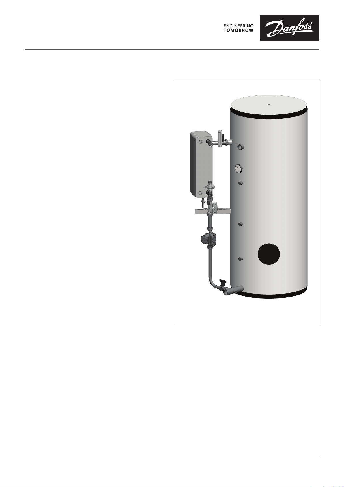
Assembly / Installing the system
Legend:
1) Domestic water (cold)
2) Domestic water (hot)
3) Circulation (connection optional)
4) Heating, supply
5) Heating, return
37) Connection for instantaneous water heater (HEL)
DTA Domestic buer tank
HEL instantaneous water heater (heat exchanger)
LPU Storage tank charging pump
D Balancing and ow control valve
SFV Safety valve
FI Thermometer (charge)
21 Thermometer (tank)
G Shut-o ball valve
M Upper connection piece
with shut-o ball valve (gunmetal)
N Lower connection piece (gunmetal)
P Heat exchanger bracket
Q Connection part (brass)
R Connection pipe (stainless steel)
Z1 Safety temperature monitor mu
(see tank data sheet)
22 Sensor mu
22 Fühlermue
Z4 Connection for sensor charge
23 Drain connection mu
25 Cleaning and inspection opening
29 Ventilation sleeve / lifting eye connection
Note:
Unused connections/mus must
be closed (plugs/caps not included)
DHS-SMT L / PL
VQ.JV.A2.02 © Danfoss 12/2018
1
Quick Guide ThermoDual®- S
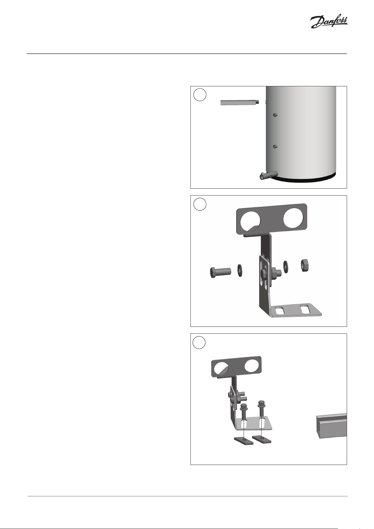
Heat exchanger bracket installation:
Screw the bracket into the mu provided for this purpose;
To fasten, you can use hemp or Teon tape.
Heat exchanger bracket:
Connect both parts with the enclosed screws,
nuts and washers.
Fastening (tightening the connections) takes place after
aligning the heat exchanger later.
1
P
2
Fasten both parts together with the enclosed screws.
Screw connection parts.
Fastening (tightening the connections) takes place after
aligning the heat exchanger later.
2
VQ.JV.A2.02 © Danfoss 12/2018
3
DHS-SMT L / PL
Quick Guide ThermoDual®- S
D
C
B
A
51 2 3 4 6 7 8
DTA
LPU
SFV
FI
29
Z1
2
Fs
3
Z2
Z3
25
25
1
G
R
Q
P
5
3
D
37
Z4
M
4
D
C
B
A
51 2 3 4 6 7 8
E
HEL
DTA
LPU
SFV
FI
29
Z1
2
Fs
3
Z2
Z3
25
25
1
G
R
Q
P
5
3
D
Z4
M
4
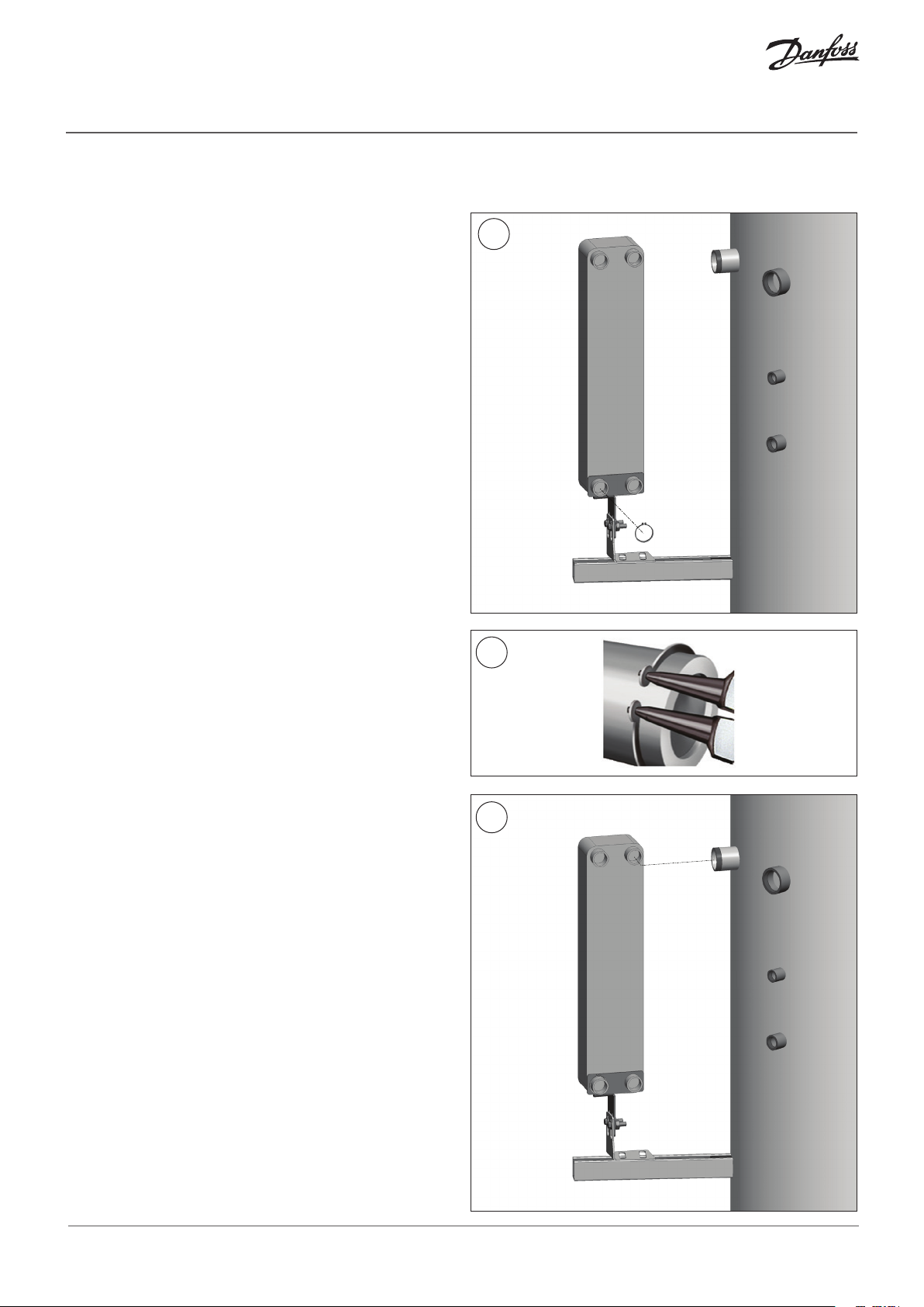
Fasten the heat exchanger using the enclosed
SEEGER ring as shown in Figure 5.
For this, use the left connection (heating, return).
4
HEL
5
Align the heat exchanger connection to t the upper
connection piece (see Fig. 7).
DHS-SMT L / PL
VQ.JV.A2.02 © Danfoss 12/2018
6
37
3

Quick Guide ThermoDual®- S
D
C
B
A
51 2 3 4 6 7 8
E
HEL
DTA
LPU
SFV
FI
29
Z1
2
Fs
3
Z2
Z3
25
25
1
G
R
Q
P
5
3
D
Z4
4
D
C
B
A
51 2 3 4 6 7 8
E
DTA
LPU
SFV
FI
29
Z1
2
Fs
3
Z2
Z3
25
1
G
R
Q
5
3
D
Z4
M
4
Connect the upper connection piece (M)
to the heat exchanger (HEL) and tank (DTA).
Insert the EPDM gaskets provided for this beforehand and
ensure horizontal alignment.
Once the connection has been successfully established, you
can rmly tighten the screws of the mounting bracket.
For the time being, manually tighten the screw connections
on the heat exchanger and tank.
7
M
37
8
37
M
DHS-SMT L / PL
VQ.JV.A2.02 © Danfoss 12/2018
HEL
4

Quick Guide ThermoDual®- S
D
C
B
A
51 2 3 4 6 7 8
E
HEL
DTA
LPU
SFV
29
Z1
2
Fs
3
Z2
Z3
25
25
1
G
R
Q
P
5
3
D
37
Z4
4
D
C
B
A
51 2 3 4 6 7 8
E
HEL
DTA
LPU
SFV
FI
29
Z1
2
3
Z2
Z3
25
25
1
G
R
Q
P
5
3
D
37
Z4
M
4
Carefully insert the capillary of the industrial thermometer
(turn it back and forth) as far as it will go into the immersion
pocket of the upper connection
piece (M) provided for this purpose.
Then fasten the thermometer from below with the existing
screw in the thermometer housing.
Now mount the tank thermometer: Seal the 200 mm
stainless steel pocket with a suitable sealing tape in the
socket provided (see tank data sheet)
and then insert the thermometer.
9
M
FI
10
This can be fastened using
the side screw in the pocket head.
21
DHS-SMT L / PL
VQ.JV.A2.02 © Danfoss 12/2018
5

Quick Guide ThermoDual®- S
D
C
B
A
51 2 3 4 6 7 8
F
E
HEL
DTA
SFV
FI
Z1
2
Fs
3
Z2
Z3
25
1
R
Q
P
5
3
D
37
Z4
M
4
D
C
B
A
51 2 3 4 6 7 8
F
E
DTA
LPU
FI
29
Z1
2
Fs
3
Z2
Z3
25
25
1
G
R
P
5
37
Z4
M
4
Screw the lower ball valve to the cold water connection.
Insert the enclosed EPDM gasket in advance.
Then tighten manually.
Connect the lower connection piece (N), the balancing
valve (D) and the connection part (Q) together one after the
other and to the charging heat exchanger (HEL).
Check the correct ow direction of the balancing valve
(upwards - see arrow on the valve body).
Use enclosed EPDM gaskets and manually tighten all
screwed connections.
The safety valve is screwed onto the
designated port R ¾” as shown.
This connection is self-sealing
and requires no additional sealing material.
11
12
G
HEL
D
SFV
N
DHS-SMT L / PL
VQ.JV.A2.02 © Danfoss 12/2018
Q
6

Quick Guide ThermoDual®- S
D
C
B
A
51 2 3 4 6 7 8
E
HEL
DTA
SFV
FI
29
Z1
2
Fs
3
Z2
Z3
25
25
1
G
R
P
5
3
D
37
Z4
M
4
D
C
B
A
51 2 3 4 6 7 8
F
E
HEL
DTA
SFV
FI
29
Z1
2
Fs
3
Z2
Z3
25
25
1
Q
P
5
3
D
37
Z4
M
4
Now connection part (Q) and
charge pump (LPU) using the EPDM gaskets.
Notice! You should also ensure the correct
ow direction of the pump here (arrow pointing up).
Lastly, you can now screw the connecting pipe (R) between
the charge pump (LPU) and the lower ball valve (G) with the
appropriate EPDM gaskets inserted.
13
Q
LPU
14
Now, if all components are positioned vertically/
horizontally and relatively stress-free, tighten all screw
connections using suitable tools.
Notice! Do not use pipe wrench pliers; for one thing,
the nuts will be damaged and there is also the danger of
excessive tightening, which can destroy the gasket.
EPDM gaskets do not require a high torque to ensure
tightness (~ 10 .. max. 35 Nm).
See also chapter 5.1 in the
installation and operating instructions
It is best to manually tighten all screw connections and
correct when lling the system only until the respective
connection no longer leaks.
R
G
LPU
DHS-SMT L / PL
VQ.JV.A2.02 © Danfoss 12/2018
7

Quick Guide ThermoDual®- S
D
C
B
A
7 8
F
E
HEL
SFV
29
Z2
Z3
25
25
1
G
Q
P
5
3
Z4
M
4
Before installing the heat exchanger’s thermal insulation
(HEL), remove with a knife about 5 mm in the lower
area as shown in Figure 15 to ensure
the insulation above the bracket will close.
15
8
VQ.JV.A2.02
Produce d by Danfoss A/S © 12/2018
 Loading...