

Quick Guide ThermoDual®-FLS
Transport / unpacking the system:
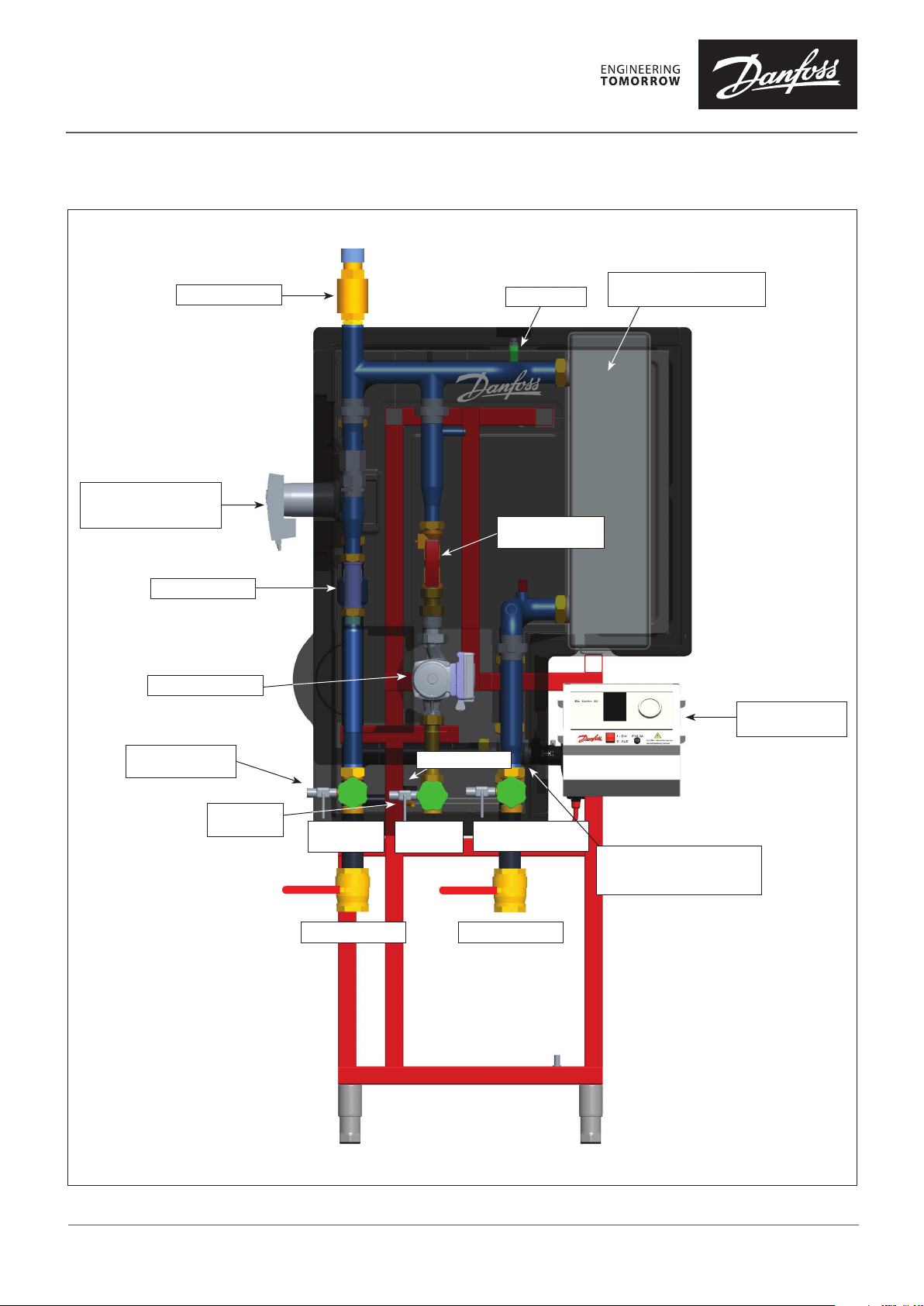
Heating pump
(only for 3-way-vale-
or pump control)
Flow sensor
Circulation pump
Safety valve
Air-vent
Balancing valve
(Taco-Setter)
Heat exchanger
(brazed)
Electronic
Controller
Drain
(Domestic water)
Drain
(Heating)
Domestic
water (cold)
Safety valve
Circulation
(Inlet)
Domestic hot water
(hot/network)
Heating supplyHeating return
Control valve
(only for 2-way-valve.
or 3-way-valve control)
DHS-SMT L / PL
VQ.MP.B1.02 © Danfoss 11/2018
1
Quick Guide ThermoDual®-FLS
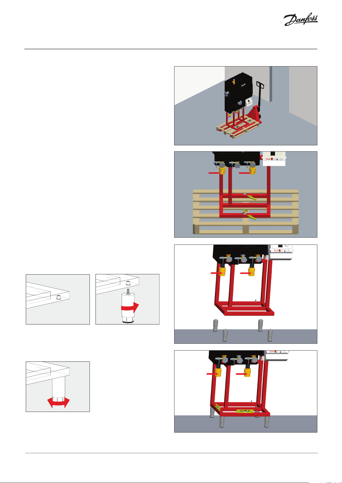
Transport / unpacking the system:
The system is delivered on a standard EUR-pallet. This
makes it easy to transport the product via a forklift
truck or pallet truck.
Remove the packaging (wooden crate/foil)
and dispose of it.
Then detach the system from the pallet;
this is fixed using 2 wooden screws.
Setting up the system:
Screw the height-adjustable, enclosed feet into the threads
beneath the frame:
Align the system horizontally by adjusting the height of the
feet, e.g. using a spirit level.
You can compensate for any unevenness of the installation
area by up to 50 mm:
For more uneven surfaces, it is first necessary to create
a level surface on site, e.g. a boiler platform or similar.
2
VQ.MP.B1.02 © Danfoss 11/2018
DHS-SMT L / PL

Quick Guide ThermoDual®-FLS
Connecting to the pipe network:
Once the system is correctly aligned at the installation site,
it can be connected to the pipe network.
Disassembly of the thermal insulation (cover):
The thermal insulation consists of 3 hard foam parts.
The back part with the left and top cover is firmly
connected to the stand frame:
In addition, pumps and valves are provided
with flexible covers.
First remove the flexible pump covers by carefully pulling
them out of the recesses of the insulating cover.
These are flexible and can be easily dismantled
by pressing them together.
DHS-SMT L / PL
VQ.MP.B1.02 © Danfoss 11/2018
3

Quick Guide ThermoDual®-FLS
The front cover can be pulled out to the front. This is
connected with the rear via multiple connectors (tongue
and groove). Pull the cover as far forward horizontally as
possible to avoid damaging the connections.
The lower end part can then be easily pulled down
obliquely since it is held only by a groove between the
front and back parts. The left wall can also be pulled
forward horizontally.
It is now possible to carry out inspection and maintenance
work on the system, such as replacing defective
components, checking for leaks or re-tightening screw
connections.
You can also check and/or regulate the flow of circulation
on the balancing valve (Taco setter) as shown
in the picture on the right:
The system can be drained after shutting off the 5 main
shut-off valves without removing the cover.
Further details can be found in the complete installation,
commissioning and operating instructions.
Reassembly of the thermal insulation:
The front insulation is installed in reverse order. Pay
particular attention to the correct positioning of the
connectors. Only when all tongue and groove connections
are correctly positioned should the front and back be
pressed together firmly.
4
VQ.MP.B1.02
Produce d by Danfoss A/S © 11/2018
 Loading...