

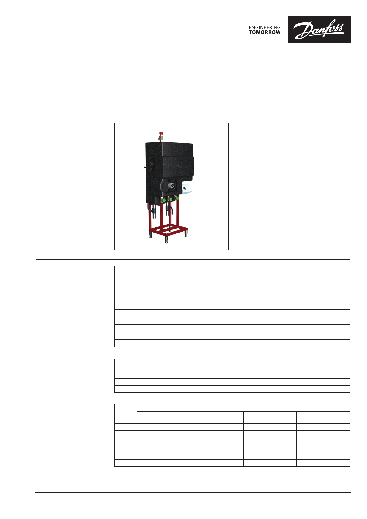
Data sheet
ThermoDual®- FLS (welded type)
General Description / Use
Maximum operating
parameters
Primary
Maximum permissible supply temperature, primary
Maximum permissible operating pressure, primary
Rated pressure, primary
Maximum permissible pressure differential, primary
Secondary
Maximum permissible temperature, secondary
Maximum permissible operating pressure, secondary
Minimum required pressure (static), water supply
Rated pressure, secondary
Mains power supply / maximum power consumption
Domestic hot water provision by instantaneous
heater is an efficient and hygienic optimal solution.
Hot water is not stored and will be produced only
on request.
Habitats for bacteria,such as legionella are virtually
non-existent. If the conditions for connection of
these systems are given (sufficiently high capacity
on heating side to cover peak load) or buffer tanks
is present, these systems can be used unrestricted.
Significant advantages of the system are:
• no storage of drinking water
• efficient cooling of the primary media
• optimum use of energy
• independent choice of different energy sources
• at any time sufficiently high domestic hot water
temperature, that fulfils all hygienic requirements
• low space requirement
• lime scale is largely avoided
90°C / 150°C (without/with safety function)
10 / 20 bar(g)
PN10 / PN25
only 2-way valve variant: 25 bar (up to 210kW) /16 bar
90°C
10 bar(g)
1.0 bar(g)
PN10
230V AC / 4.0 A
Pumps and 3-way valve variant /
2-way valve variant
Materials
Code numbers
© Danfoss | 2019.08
Pipes, fittings, flanges, valves (domestic side)
ditto (heating side) P235GH-TC1, CuSn5Pb5Zn5-C (RG -5), ST37.0, EN-JL 1040 (GG25)
Heat exchanger 1.4404 with Cu solder
Insulation Hardcover PU hard foam λ=0.029 W/mK (100%ENEV)
Capacity
[ kW]
140 00 4X1814 00 4X1808 004X1653 0 04X1659
210 004X1815 004X1809 004X1654 004X1660
280 00 4X1816 00 4X1810 004X1655 004X1661
350 0 04X1817 00 4X1811 004X1656 00 4X1662
420 004X1818 004X1812 004X1657 00 4X1663
455 004X1819 0 04X1813 00 4X1658 004X1664
Pump +
3-way mixing valve
Pump control
(PWM control signal)
1.4571, bronze or brass as per DIN EN 1982,
also considering DIN 50930-06 and UBA guidelines
Code no.
2-way valve
(without safety function)
2-way valve
(with safety function)
VD.HE.J7.02 | 1
Data sheet ThermoDual®- FLS
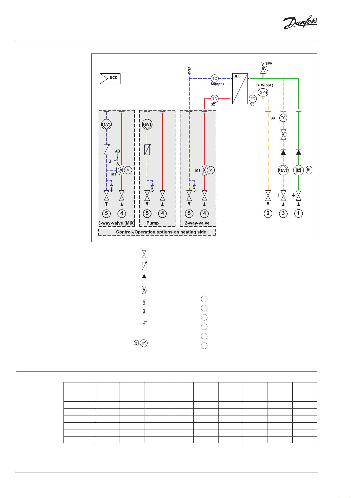
Circuit diagram
Technical data
HEL Heat exchanger
P1 Heating pump
P3 Circulation pump
SFV Safety valve
M1 Motorized control valve (2/3-way)
ECD Electronic domestic hot water controller (ECL310 / P318.10)
STW Safety thermostat (optional)
BTA Hot water buffer tank (installed by customer)
1 Domestic water (cold)
2 Domestic hot water (hot network)
3 Circulation (inlet)
4 Heating supply
5 Heating return
TC Sensors (general: direct , immersion, surface)
“S2”: with designation as for controller
3-way
dpr
[kPa]
FR
DW
(10 ->60 °C)
[m3/h]
DW
dp
[kPa]
*
FR
C
(55 ->60°C )
[m3/h]
Typ e
ThermoDual®
Capacity
[kW]
p
FR
(70 ->25° C)
[m3/h]
Shut-off valve
Non-return valve
Check valve
Balancing valve
Air vent
Drain
Drain, sampling valve
(optional)
F1: Flow sensor
Pump
dpr
[kPa]
2-way
dp
[kPa]
FLS 14 0 140 2,4 52 21 38 2,4 12 1,0 / 2,4 80 / 43
FLS 210 210 3,8 95 30 81 3,6 26 1,5 / 2,4 70 / 43
FLS 280 280 5,1 86 29 76 4,8 28 2,0 / 2,4 57 / 45
FLS 350 350 6,3 74 30 59 6,0 33 2,5 / 3,4 51 / 30
FLS 420 420 7,8 53 30 54 7,2 41 3,0 / 3,4 38 / 30
FLS 455 455 8,0 59 22 54 7, 8 39 3, 3 / 3,4 34 / 31
FR: Flow rate p: primary dpr: Remaining pump head dp: Pressure loss DW: Domestic water C: Circulation
* flow rate: standard setup / maximal possible
** remaining pump head for: standard setup / maximal possible
C
dpr**
[kPa]
2 | © Danfoss | 2019.08
VD.HE.J7.02

Data sheet ThermoDual®- FLS
Function
Dimensions
Flow systems provide heated domestic water when requested. By a heat exchanger (HEL), the cold
water flowing into connection (1) will be heated up to set point and provided to the consumer at the
connection (2). The electronic controller (ECD) is measuring the relevant temperatures and controls the
target values that are held constant in all operating conditions. This is i.e. achieved by influencing the
speed of the heating pump (P1), so that the outlet temperature always matches the specified value. In
case of using a control valve, the flow is directly controlled by an electrical actuator. Short-term peaks
in consumption are registered at the flow sensor to intervene quickly and avoid large temperature
fluctuations. The cooled- circulation water from the network (connection 3) is constantly heated in
heat exchanger (HEL), even in times of draw-off , reheated and the temperature control (sensor) in the
amount of the controlled circulation pump (P3) influenced so that only the necessary amount flows to
maintain constant power set point.
The capacity for the peak load is to ensure either by buffering heating water in a tank (BTA) or there
must be a sufficiently large connection value available. The Recharging of a buffer (e.g. from a boiler)
can a requisition (sensor / switch contact) on controller (ECD) using an on-site charging pump (LPU). The
operation of the system by a controlled heating pump (P1) is only possible without differential pressure
between the connections (4) and (5).
Connections: Weight [kg]
Typ e
ThermoDual®
FLS 14 0 1 ¼”A 1 ¼”A 1 ¼” 42,4 93 90 99
FLS 210 1 ¼”A 1 ¼”A 1 ¼” 42,4 96 93 10 0
FLS 280 1 ½”A 1 ¼”A 1 ½” 48,3 102 98 107
FLS 350 1 ½”A 1 ¼”A 1 ½” 48,3 107 102 111
FLS 420 1 ¾”A 1 ¼”A 2” 60,3 116 10 6 120
FLS 455 1 ¾”A 1 ¼”A 2” 60,3 122 112 126
DW C/H Circ.
1/2 G ISO 3 G ISO
HTG (DN)
SL, RL
4/5 PN10 Rp4/5 PN25
HTG (DN)
SL, RL
WELD
Pump +
3-way v.
Pump
control
(PWM)
2-w ay v.
935
132
338
488
1830
1
3
2
Correlation of connections
5
156 174 174
4
415
640
1 Domestic cold water
2 Domestic hot water
3 Circulation (inlet)
VD.HE.J7.02
110 –16 0
4 Heating supply line
5 Heating return line
© Danfoss | 2019.08 | 3
Danfos
produc
Al
Danfoss A/S
Heating Segment • heating
Data sheet ThermoDual®- FLS
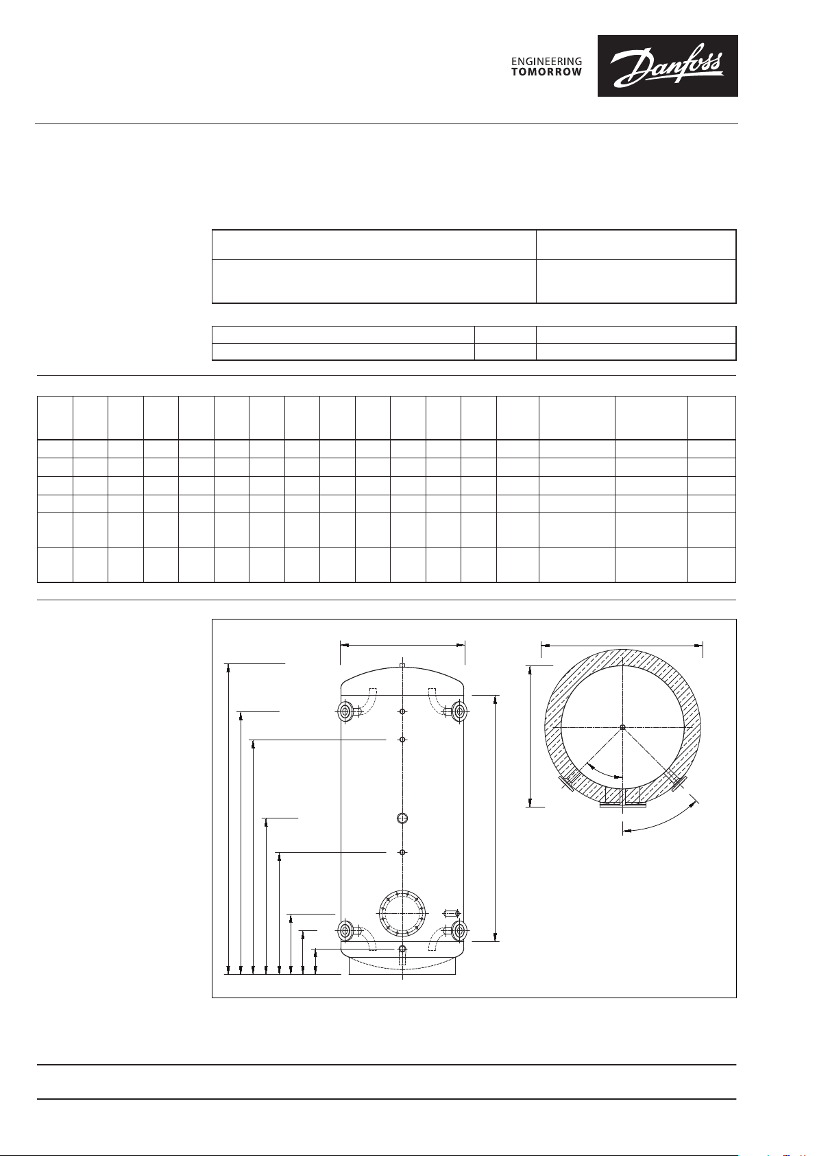
Accessories
Heating buffer storage tank, standing model,
Typ e: PSS
Charging-/Discharging Connections
as flange connection
Materials
Maximum operating
parameters
Typ e IH mmH1 mmH2 mmH3 mmH4 mmH5 mmH6 mmH7 mmHMa mmd mmDx mmD
300 1450 1270 1070 780 620 320 215 115 1130 550 660 710 1550 DN 25 / PN 16 640U4984 85
500 1860 1665 1430 990 650 350 245 145 155 0 600 710 800 2010 DN 40 / PN 16 640U4985 115
750 1870 1635 1400 1000 670 370 265 165 150 0 750 860 950 1945 DN 40 / PN 16 640U4986 175
1000 1910 1655 1370 1020 690 390 285 185 150 0 850 960 1050 2090 DN 50 / PN 16 640U4987 240
150 0 2030 1740 1505 1070 725 445 320 220 1550 1000 111 0 1200 2160 DN 50 / PN 16
2000 2 310 1995 175 0 12 20 770 510 375 265 1770 11 00 1210 130 0 2450 DN 65 / PN 16
tank (shell)
Insulation (from 1500 Liter as bypack/not mounted)
Maximum permissible operating temperature TZ 110 ° C
Maximum permissible operating pressure PZ 6 bar
mm
Steel EN 1.0025 S235JRG2
Raw inside, outside undercoat - black
Insulation, polyester fiber fleece + EPS
white, CFC-free,silver with
polypropylene top layer
Tilted
height mmconnections codes
640U4988
+ 640U4994
640U4989 +
640U4995
Weight
kg
325
375
d
24
4
H
H1
H2
H3
H4
H5
H6
5
H7
22
22
6
22
25
26
4
Dx
H max
4 Charging-/Discharging conn. supply (hot)
22
5
5 Charging-/Discharging conn. return (cold)
6 Solar conn. / Reserve El. Heater Rp 2“
22 Thermostat / Thermometer Rp 1/2“
24 Air Vent Rp 3/4“
25 Inspection, diameter opening
219 mm (DN200 / PN6)
26 Drain Rp 3/4“
D
45°
45°
s can accept no responsibility for possible errors in catalogues, brochures and o ther printed material. Danfoss reserves the right to alter its products w ithout notice. This also applies to
ts already on order provided that such alterations can be m ade without subsequential changes being necessary in specications already agreed.
l trademarks in this material are p roperty of the respective companies. Danfoss and all Danfoss logot ypes are trademarks of Danfoss A/S. All rights reserved.
4 | © Danfoss | DHS-SDBT/PL | 2019.08
.danfoss.com • +45 7488 2222 • E-Mail: heating@danfoss.com
VD.HE.J7.02
 Loading...