

Page 1
InstallationGuide
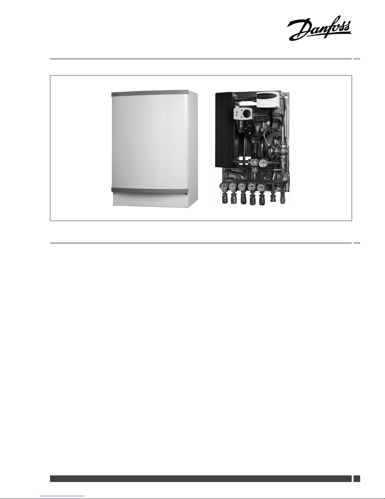
TermixVMTDCompact20
1.0TableofContents
1.0TableofContents.............................................1
........................................................................2
2.0VMTD-C20Functionaldescription.....................3
3.0Safetynotes.....................................................4
SafetyNotes—general...........................................4
4.0Mounting........................................................5
4.1Mounting...........................................................5
4.2Start-up..............................................................7
4.3Electricalconnections.............................................8
5.0Design.............................................................9
5.1Design...............................................................9
5.2Schematicdiagram................................................10
6.0Controls..........................................................12
6.1Heatingcircuit......................................................12
6.2DHWtemperaturecontrol........................................14
6.3Other.................................................................15
6.4Maintenance........................................................17
7.0Troubleshooting..............................................18
7.1Troubleshootingingeneral......................................18
7.2TroubleshootingDHW............................................18
7.3TroubleshootingHE...............................................19
7.4Disposal.............................................................20
8.0Declaration......................................................23
8.1Declarationofconformity........................................23
DanfossHeating
VI.CW.W2.02/LUK41200
DEN-GT
1
Page 2
InstallationGuideTermixVMTDCompact20
2
DEN-GT
VI.CW.W2.02/LUK41200
DanfossHeating
Page 3
InstallationGuideTermixVMTDCompact20
2.0VMTD-C20Functionaldescription
Districtheatingsubstationfordirectheatingand
instantaneousdomestichotwaterwiththermostaticor
electroniccontrols.Designedforwall-mounting.
Application
TheTermixVMTDCompact20substationisacompletesolution
withbuilt-inwaterheaterandheatingcircuitwithdifferential
pressurecontrols.Thesubstationisapplicableformulti-family
housesandapartmentbuildings.
Districtheating(DH)
Thedistrictheatingcircuitisprefabricatedwithadifferential
pressurecontrolleraswellasthermometersandballvalves.
Furthermorethesubstationisdeliveredwithamixingloop
includingpump,controlsandnon-returnvalve.
Heating(HE)
Theheatingcircuitisdesignedfordirectconnection.The
differentialpressurecontrollersetstheoptimumoperation
conditionsforradiatorthermostatsinordertoenableindividual
temperaturecontrolineachroom.Themixingloopcreatesa
suitabletemperaturelevelfortheheatingsystem.
Domestichotwater(DHW)
Thedomestichotwaterispreparedintheplateheatexchanger
andthetemperatureisregulatedwithathermostaticor
electro-niccontroller.TheefcientheatexchangerforDHW
offersexceptionallygoodheatextractionwithhighoutput.No
readjustmentoftheDHWtemperatureisrequiredafterinstallation
andinitialsettingofthecontrols.Thethermostaticcontrol
valveautomaticallyretainsthecomforttemperatureofthehot
water,evenwhentheheatingsystemisinreducedoperation
duringsummerorifthedistrictheatingplantchangesope-rating
parametersbetweensummerandwinter .Thiseitherbylowering
orincreasingtheowtemperatureofthedistrictheatingwater
and/ortheoperatingpressureinthenetwork.
DanfossHeating
VI.CW.W2.02/LUK41200
DEN-GT
3
Page 4
InstallationGuideTermixVMTDCompact20
3.0Safetynotes
Thefollowinginstructionsrefertothestandarddesignof
substation.Specialversionsofsubstationsareavailableon
request.
Thisoperatingmanualshouldbereadcarefullybeforeinstallation
andstart-upofthesubstation.Themanufactureracceptsno
liabilityfordamageorfaultsthatresultfromnon-compliancewith
theoperatingmanual.Pleasereadandfollowalltheinstructions
carefullytopreventaccidents,injuryanddamagetoproperty.
Assembly,start-upandmaintenanceworkmustbeperformedby
qualiedandauthorizedpersonnelonly.
Pleasecomplywiththeinstructionsissuedbythesystem
manufacturerorsystemoperator.
Corrosionprotection
Allpipesandcomponentsaremadeofstainlesssteelandbrass.
Themaximumchloridecompoundsoftheowmediumshouldnot
behigherthan150mg/l.
Theriskofequipmentcorrosionincreasesconsiderablyifthe
recommendedlevelofpermissiblechloridecompoundsis
exceeded.
Energysource
Thesubstationisdesignedfordistrictheatingastheprimary
sourceofenergy.However,alsootherenergysourcescanbeused
wheretheoperatingconditionsallowitandalwaysarecomparable
todistrictheating.
Application
Thesubstationisdesignedtobeconnectedtothehouse
installationinafrost-freeroom,wherethetemperaturedoesnot
exceed50°Candthehumiditydoesnotexceed60%.Donotcover
orwallupthesubstationorinanyotherwayblocktheentrance
tothestation.
Choiceofmaterial
Choiceofmaterialsalwaysincompliancewithlocallegislation.
Safetyvalve(s)
Werecommendmountingofsafetyvalve(s),however,alwaysin
compliancewithlocalregulations.
Connection
Thesubstationmustbeequippedwithfeaturesthatensurethat
thesubstationcanbeseparatedfromallenergysources(also
powersupply).
Emergency
Incaseofdangeroraccidents-re,leaksorotherdangerous
circumstances-interruptallenergysourcestothestationif
possible,andseekexperthelp.
Incaseofdiscolouredorbad-smellingdomestichotwater,closeall
shut-offvalvesonthesubstation,informtheoperatingpersonnel
andcallforexperthelpimmediately.
Storage
Anystorageofthesubstationwhichmaybenecessarypriorto
installationshouldbeinconditionswhicharedryandheated.
Authorizedpersonnelonly
Assembly,start-upandmaintenanceworkmustbeperformedby
qualiedandauthorizedpersonnelonly.
Pleaseobserveinstructionscarefully
Toavoidinjurytopersonsanddamagetothedevice,itisabsolutely
necessarytoreadandobservetheseinstructionscarefully.
Warningofhighpressureandtemperature
Beawareoftheinstallation’ spermissiblesystempressureand
temperature.
Themaximumtemperatureoftheowmediuminthesubstationis
120°C.
Themaximumoperatingpressureofthesubstationis10bar.PN16
versionsareavailableonenquiry.
Theriskofpersonsbeinginjuredandequipmentdamagedincreases
considerablyiftherecommendedpermissibleoperatingparameters
areexceeded.
Thesubstationinstallationmustbeequippedwithsafetyvalves,
however,alwaysinaccordancewithlocalregulations.
Warningofhotsurface
Thesubstationhasgothotsurfaces,whichcancauseskinburns.
Pleasebeextremelycautiousincloseproximitytothesubstation.
Powerfailurecanresultinthemotorvalvesbeingstuckinopen
position.Thesurfacesofthesubstationcangethot,whichcancause
skinburns.Theballvalvesondistrictheatingsupplyandreturnshould
beclosed.
Warningoftransportdamage
Beforesubstationinstallation,pleasemakesurethatthesubstation
hasnotbeendamagedduringtransport.
IMPORTANT-Tighteningofconnections
Duetovibrationsduringtransportallangeconnections,screwjoints
andelectricalclampandscrewconnectionsmustbecheckedand
tightenedbeforewaterisaddedtothesystem.Afterwaterhasbeen
addedtothesystemandthesystemhasbeenputintooperation,
re-tightenALLconnections.
4
DEN-GT
VI.CW.W2.02/LUK41200
DanfossHeating
Page 5
InstallationGuideTermixVMTDCompact20
4.0Mounting
4.1Mounting
Installationmustbeincompliancewithlocalstandardsand
regulations.
Districtheating(DH)-Inthefollowingsections,DHreferstothe
heatsourcewhichsuppliesthesubstations.Avarietyofenergy
sources,suchasoil,gasorsolarpower,couldbeusedasthe
primarysupplytoDanfosssubstations.Forthesakeofsimplicity,
DHcanbetakentomeantheprimarysupply.
Connections:
1.Districtheating(DH)supply
2.Districtheating(DH)return
3.Heating(HE)supply
4.Heating(HE)return
5.Domestichotwater(DHW)
6.Domesticcoldwater(DCW)
7.Hotwatercirculation(HWC)
Connectionsizes:
DH+HE:
G1”(int.thread)
DCW+DHW:
G1”(int.thread)
HWC:
G¾”(int.thread)
Dimensions(mm):
Withoutcover:
H815xW505xD300
Withcover:
H815xW540xD360
Weight(approx.):30–40kg
Authorizedpersonnelonly
Assembly,start-upandmaintenanceworkmustbeperformedby
qualiedandauthorizedpersonnelonly.
Thepipeplacementcandeviatefromtheshowndrawing.Pleasenote
themarkingsonthestation.
DanfossHeating
VI.CW.W2.02/LUK41200
DEN-GT
5
Page 6
InstallationGuideTermixVMTDCompact20
4.1.1Installation
Mounting:
Adequatespace
Pleaseallowadequatespacearoundthesubstationformounting
andmaintenancepurposes.
Orientation
Thestationmustbemountedsothatcomponents,keyholes
andlabelsareplacedcorrectly.Ifyouwishtomountthestation
differentlypleasecontactyoursupplier.
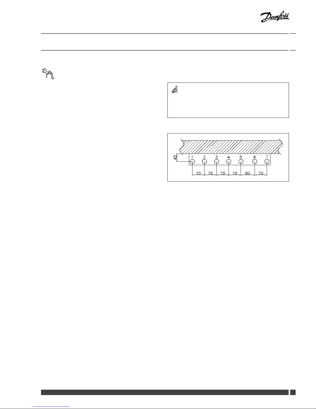
Drillings
Wheresubstationsaretobewall-mounted,drillingsareprovided
inthebackmountingplate.Floormountedunitshavesupport.
Labelling
Eachconnectiononthesubstationislabelled.
Beforeinstallation:
Cleanandrinse
Priortoinstallation,allsubstationpipesandconnectionsshouldbe
cleanedandrinsed.
Thightening
Duetovibrationduringtransport,allsubstationconnectionsmust
becheckedandtightenedbeforeinstallation.
Unusedconnections
Unusedconnectionsandshut-offvalvesmustbesealedwitha
plug.Shouldtheplugsrequireremoval,thismustonlybedoneby
anauthorizedservicetechnician.
Installation:
Strainer
Ifastrainerissuppliedwiththestationitmustbettedaccording
toschematicdiagram.Pleasenotethatthestrainermaybe
suppliedloose.
Connections
Internalinstallationanddistrictheatingpipesconnectionsmustbe
madeusingthreaded,angedorweldedconnections.
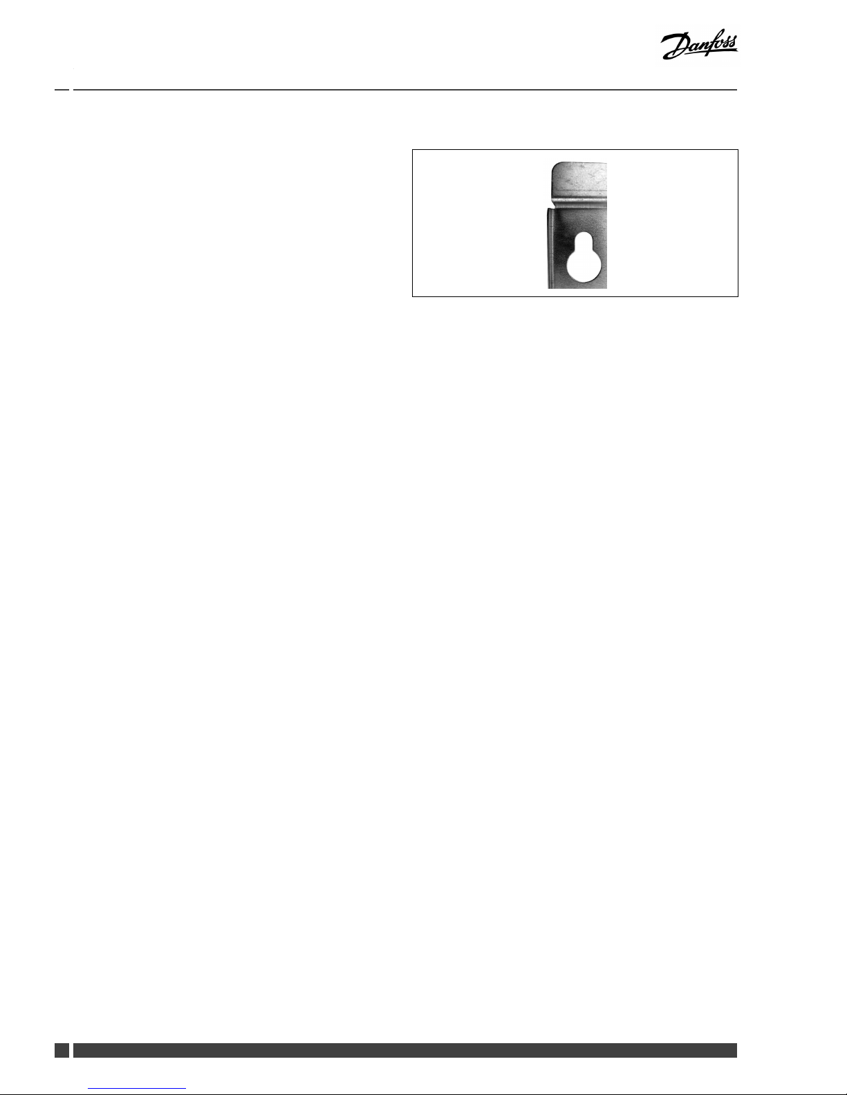
Keyholeformounting.
6
DEN-GT
VI.CW.W2.02/LUK41200
DanfossHeating
Page 7
InstallationGuideTermixVMTDCompact20
4.2Start-up
Start-up,Heatingwithmixingloop
Start-up:
1:Pumpspeed
Setthepumptohighestspeedbeforestart-up.
2:Startpump
Startthepumpandheatthroughthesystem.
3:Openshut-offvalves
Theshut-offvalvesshouldthenbeopenedandtheunitobserved
asitentersservice.Visualcheckingshouldconrmtemperatures,
pressures,acceptablethermalexpansionandabsenceofleakage.
Ifthesystemoperatesinaccordancewithdesign,itcanbeput
toregularuse.
4:Ventsystem
Switchoffthepumpandventtheinstallationaftertheradiators
havebeenwarmedup.
5:Adjustpumpspeed
Setthepumptothelowestspeedconsistentwithcomfortand
electricityconsumption.
Normallythechange-overswitchissetinthemidposition(default).
Howeverforsystemswithunderoorheatingorsinglepipeloop
systems,itmaybenecessarytoturnthechange-overswitch
upwards.
Higherpumpspeedsareonlyusediftheheatingrequirement
increases.
Re-thightenconnections
Afterwaterhasbeenaddedtothesystemandthesystemhasbeen
putintooperation,re-tightenALLconnections.
Pump
Thepumpmustbeswitchedoffduringsystemll.
Underoorheating:
Pumpstopfunction
Ifthesubstationisusedinconnectionwithunderoorheating,the
circulationpumpmustbeconnectedtothepumpstopfunctionin
theunderoorheatingcontroller .Thepumpmustbestoppedif
allunderoorheatingcircuitsareclosed.
Warranty
Ifthisisnotpossible,thenowmustbecontinuedthroughthe
by-pass.Failingthis,thepumpwillbeatriskofseizureandany
remainingwarrantywillbewithdrawn.
Summeroperation:
Switchoffpump
Insummerthecirculationpumpmustbeswitchedoffandthe
shut-offvalvetoHEsupplyclosed.
Runningpumpbi-weekly
Itisrecommendedtostartupthecirculationpump(for2minutes)
onceamonthduringsummer;theshut-offvalveoftheHEsupply
mustbeshut.
Electroniccontroller
Mostelectroniccontrollerswillstartupthepumpautomatically
(pleasenotemanufacturer´sinstructions).
DanfossHeating
VI.CW.W2.02/LUK41200
DEN-GT
7
Page 8

InstallationGuideTermixVMTDCompact20
4.3Electricalconnections
Beforemakingelectricalconnections,pleasenotethe
following:
Safetynotes
Pleasereadtherelevantpartsofthesafetynotes.
230V
Thesubstationmustbeconnectedto230VACandearth.
Disconnection
Thesubstationmustbeelectricallyconnectedsothatitcanbe
disconnectedforrepairs.
Outdoortemperaturesensor
Outdoorsensorsshouldbemountedsoastoavoidexposureto
directsunlight.Theyshouldnotbeplacedclosetodoors,windows
orventilationoutlets.
Theoutdoorsensormustbeconnectedtothestationonthe
terminalblockundertheelectroniccontrol.
Authorizedelectrician
Electricalconnectionsmustbemadebyanauthorizedelectricianonly.
Localstandards
Electricalconnectionsmustbemadeinaccordancewithcurrent
regulationsandlocalstandards.
8
DEN-GT
VI.CW.W2.02/LUK41200
DanfossHeating
Page 9

InstallationGuideTermixVMTDCompact20
5.0Design
5.1Design
Yoursubstationmightlookdifferentthanthesubstationshown.
Designdescription
B
Heatexchanger,DHW
11
Domestichotwaterpump
F
Electroniccontroller
27
Actuator,HE
7
Thermostaticcontroller,DHW
31
Differentialpressurecontroller
10
Circulationpump,HE
DanfossHeating
VI.CW.W2.02/LUK41200
DEN-GT
9
Page 10

InstallationGuideTermixVMTDCompact20
5.2Schematicdiagram
TermixVMTDCompact20-Electronic/thermostaticschematicdiagram
DH
Supply
HE
Supply
DH
Return
HE
Return
DHW
DCW
HWC
Yoursubstationmightlookdifferentthantheschematicdiagramshown.
Schematicdescription
B
Heatexchanger,DHW
11
Domestichotwaterpump
24
Deliveredloosewithunit
F
Electroniccontrollerheating
16
Outdoorsensor
27
Actuator
1
Ballvalve
18
Thermometer
29
2-waymotorizedvalve
2
Singlecheckvalve
19
Surfacesensor
31
Differentialpressurecontroller
10
Circulationpump
23
Ballvalve
10
DEN-GT
VI.CW.W2.02/LUK41200
DanfossHeating
Page 11

InstallationGuideTermixVMTDCompact20
TermixVMTDCompact20-Electronicschematicdiagram
DH
Supply
HE
Supply
DH
Return
HE
Return
DHW
DCW
HWC
Yoursubstationmightlookdifferentthantheschematicdiagramshown.
Schematicdescription
B
Heatexchanger,DHW
10
Circulationpump
23
Ballvalve
F
Electroniccontrollerheating
11
Domestichotwaterpump
24
Deliveredloosewithunit
1
Ballvalve
16
Outdoorsensor
27
Actuator
2
Singlecheckvalve
18
Thermometer
29
2-waymotorizedvalve
7
Thermostaticvalve
19
Surfacesensor
31
Differentialpressurecontroller
DHW:DomesticHotWater
DCW:
DomesticColdWater
HWC:
HotWaterCirculation
DHSupply:DistrictHeatingSupply
DHReturn:DistrictHeatingReturn
HESupply:HeatingSupply
HEReturn:HeatingReturn
5.2.1Technicalparameters
Technicalparameters
Nominalpressure:
PN16
Max.DHsupplytemperature:
120°C
Min.DCWstaticpressure:
0,5bar
Brazingmaterial(HEX):
Copper
Heatexchangerstestpressure:30bar
Soundlevel:≤55dB
DanfossHeating
VI.CW.W2.02/LUK41200
DEN-GT
11
Page 12

InstallationGuideTermixVMTDCompact20
6.0Controls
6.1Heatingcircuit
6.1.1Differentialpressurecontroller
Thedifferentialpressurecontrollersmoothsouttheuctuationsin
pressurearrivingfromthedistrictheatingnetwork.Theoperating
pressureinthesubstationisthusheldsteady.
6.1.2RAVKcontroller
HEtemperaturecontrol
TheHEowtemperatureintheheatingcircuitiscontrolledbythe
HEtemperaturecontroller.
Thermostaticcontrol
ThetemperatureoftheHEowlineisadjustedasfollows:
Toincreasetemperature,turnthehandleonthethermostatic
controllertoselectahighernumber.
Todecreasetemperature,turnthehandleonthethermostatic
controllertoselectalowernumber .
RAVKcontroller(25-65°C).Thetemperaturesettingisasfollows:
1=25°C
2=35°C
3=45°C
4=55°C
5=65°C
Thevaluesareintendedasaguide.
12
DEN-GT
VI.CW.W2.02/LUK41200
DanfossHeating
Page 13

InstallationGuideTermixVMTDCompact20
6.1.3Flowcontrollerwithintegratedcontrolvalve
Thecontrollerisaself-actingowcontrollerwithintegratedcontrol
valve.Thecontrollercloseswhensetmax.owisexceededand
canbeusedincombinationwithDanfosselectricalactuatorswith
orwithoutsafetyfunction.Springreturnmotorcanbeusedas
safetyfunctionbypowerfailure.
6.1.4Electroniccontrol
Substationswithelectroniccontrolmustbesetinaccordancewith
manufacturer´sinstructions.
Wheretheroomtemperatureiscontrolledbyradiatorthermostats,
itisrecommendedthatthermostatsbesetforminimum
temperatureineachroom.
6.1.5Outdoortemperaturesensor(ESMT)
Outdoorsensorsshouldbemountedsoastoavoidexposureto
directsunlight.Theyshouldnotbeplacedclosetodoors,windows
orventilationoutlets.
DanfossHeating
VI.CW.W2.02/LUK41200
DEN-GT
13
Page 14

InstallationGuideTermixVMTDCompact20
6.1.6Circulationpump
ALPHA2pumpshavebothvariablespeedpressurecontrolled
operation,andstandardselectablethreespeedoperation.
TheuniqueAUTOADAPTfeatureallowsthepumptomatchits
performancetothesystemrequirements,helpingtoreducenoise
whenthermostaticvalvesareclosingdown.
EnergylabellingclassA
ALPHA2Lpumpshavebothvariablespeedpressurecontrolled
operation,andstandardselectablethreespeedoperation.The
variablespeedmodulatingmodesallowthepumptomatchits
performancetothesystemrequirements,helpingtoreducenoise
whenthermostaticvalvesareclosingdown.
EnergylabellingclassA
UPSpumpsareacompleterangeofcirculatorpumpswith3
speeds.
EnergylabellinguptoclassB
6.2DHWtemperaturecontrol
DHWtemperaturecontrol
TherearevarioustypesofDHWtemperaturecontrolusedin
Danfosssubstations.
DHWtemperatureshouldbeadjustedto45-50°C,asthisprovides
optimalutilisationofDHwater.AtDHWtemperaturesabove55°C,
thepossibilityoflimescaledepositsincreasessignicantly.
14
DEN-GT
VI.CW.W2.02/LUK41200
DanfossHeating
Page 15

InstallationGuideTermixVMTDCompact20
6.2.1AVTBcontroller(20–60°)
Thetemperaturesettingisasfollows:
1=20°C
2=35°C
3=50°C
4=60°C
5=70°C
Thevaluesareintendedasaguide.
TheAVTBoperatesatitsbestatDHsupplytemperaturesofupto
90°C.
Thermostaticcontrol
DHWtemperatureisadjustedasfollows:
Toincreasetemperature,turnthehandleonthethermostatic
controllertoselectahighernumber.
Todecreasetemperature,turnthehandleonthethermostatic
controllertoselectalowernumber .
6.2.2Electric2–waymotorizedvalve
Actuatorswithorwithoutsafetyfunctionareavailablefor3-point
controls.Spring-returnactuatorscanbeusedtoprovidesafety
shut-offintheeventofpowerfailure.
6.3Other
6.3.1Safetyvalve
Thepurposeofthesafetyvalveistoprotectthesubstationfrom
excessivepressure.
Theblow-offpipefromthesafetyvalvemustnotbeclosed.The
blow-offpipeoutletshouldbeplacedsothatitdischargesfreely
anditispossibletoobserveanydrippingfromthesafetyvalve.
Itisrecommendedtochecktheoperationofsafetyvalvesat
intervalsof6months.Thisisdonebyturningthevalveheadin
directionindicated.
DanfossHeating
VI.CW.W2.02/LUK41200
DEN-GT
15
Page 16

InstallationGuideTermixVMTDCompact20
6.3.2Strainer
Strainersshouldbecleanedregularlybyauthorizedpersonnel.The
frequencyofcleaningwoulddependonoperatingconditionsand
themanufacturer’sinstructions.
6.3.3Domestichotwaterpump
Important!
Itisnecessarytomountadomestichotwatercirculationpumpon
thewaterheatertoavoidregulationproblems.
Thecirculationpumpcannotbeswitchedoff,sincethiswillresult
inregulationproblems.(noowatthesensor).
16
DEN-GT
VI.CW.W2.02/LUK41200
DanfossHeating
Page 17

InstallationGuideTermixVMTDCompact20
6.4Maintenance
Thesubstationrequireslittlemonitoring,apartfromroutine
checks.Itisrecommendedtoreadtheenergymeteratregular
intervals,andtowritedownthemeterreadings.
RegularinspectionsofthesubstationaccordingtothisInstruction
arerecommended,whichshouldinclude:
Strainers
Cleaningofstrainers.
Meters
Checkingofalloperatingparameterssuchasmeterreadings.
Temperatures
Checkingofalltemperatures,suchasDHsupplytemperatureand
DHWtemperature.
Connections
Checkingallconnectionsforleakages.
Safetyvalves
Theoperationofthesafetyvalvesshouldbecheckedbyturning
thevalveheadintheindicateddirection.
Venting
Checkingthatthesystemisthoroughlyvented.
Inspectionsshouldbecarriedoutminimumeverytwoyears.
SparepartscanbeorderedfromDanfoss.Pleaseensurethatany
enquiryincludesthesubstationserialnumber.
Authorizedpersonnelonly
Assembly,start-upandmaintenanceworkmustbeperformedby
qualiedandauthorizedpersonnelonly.
DanfossHeating
VI.CW.W2.02/LUK41200
DEN-GT
17
Page 18

InstallationGuideTermixVMTDCompact20
7.0Troubleshooting
7.1Troubleshootingingeneral
Intheeventofoperatingdisturbances,thefollowingbasicfeatures
shouldbecheckedbeforecarryingoutactualtroubleshooting:
•thesubstationisconnectedtoelectricity,
•thestrainerontheDHsupplypipeisclean,
•thesupplytemperatureoftheDHisatthenormallevel
(summer,atleast60°C-winter,atleast70°C),
•thedifferentialpressureisequaltoorhigherthanthenormal
(local)differentialpressureintheDHnetwork–ifindoubt,ask
theDHplantsupervisor,
•pressureonthesystem-checktheHEpressuregauge.
Authorizedpersonnelonly
Assembly,start-upandmaintenanceworkmustbeperformedby
qualiedandauthorizedpersonnelonly.
7.2TroubleshootingDHW
ProblemPossiblecauseSolution
Strainerinsupplyorreturnlineclogged.Cleanstrainer(s).
DHWcirculationpumpoutoforderorwith
toolowsetting.
Checkcirculationpump.
Defectiveorcloggednon-returnvalve.
Replace–clean.
Noelectricity.Check.
Wrongsettingofautomaticcontrols,ifany.Toadjustanelectroniccontrollerfor
DHW,pls.noteenclosedinstructionsfor
electroniccontroller.
Scalingoftheplateheatexchanger.
Replace–rinseout.
Defectivemotorizedvalve.Check(usemanualfunction)–replace.
Defectivetemperaturesensors.
Check–replace.
ToolittleornoDHW.
Defectivecontroller.
Check–replace.
DCWisbeingmixedwiththeDHW,e.g.in
adefectivethermostaticmixingvalve.
Check–replace.
Hotwaterinsometapsbutnotinall.
Defectiveorcloggednon-returnvalveon
circulationvalve.
Replace–clean.
Taptemperaturetoohigh;DHWtapload
toohigh.
Thermostaticvalveadjustedtoatoohigh
level.
Check–set.
Scalingoftheplateheatexchanger.
Replace–rinseout.
Temperaturedropduringtapping.
LargerDHWowthanthesubstationhas
beendesignedfor .
ReduceDHWow.
Thermostaticcontrolvalvedoesnotclose
TemperaturedifferencebetweenDH
supplyandDHWsetpointtoolow.
Lowerthesetpointtemperatureor
increasetheDHsupplytemperature.
18
DEN-GT
VI.CW.W2.02/LUK41200
DanfossHeating
Page 19

InstallationGuideTermixVMTDCompact20
7.3TroubleshootingHE
ProblemPossiblecauseSolution
Toolittleornoheat.StrainercloggedinDHorHEcircuit
(radiatorcircuit).
Cleangate/strainer(s).
ThelterintheenergymeteronDHcircuit
clogged.
Cleanthelter(afterconsultingtheDH
plantoperator).
Defectiveorwronglyadjusteddifferential
pressurecontroller.
Checktheoperationofthedifferential
pressurecontroller–cleanthevalveseatif
required.
Sensordefective–orpossiblydirtinthe
valvehousing.
Checktheoperationofthethermostat–
cleanthevalveseatifrequired.
Automaticcontrols,ifany,wronglysetor
defective-possiblypowerfailure.
Checkifthesettingofthecontroller
iscorrect–seeseparateinstructions.
Checkthepowersupply.Temporary
settingofmotorto“manual”control–see
instructionsonautomaticcontrols.
Pumpoutofoperation.Checkifthepumpisreceivingpowerand
thatitturns.Checkifthereisairtrappedin
thepumphousing–seepumpmanual.
Thepumpissetattoolowspeedof
rotation.
Setthepumpathigherspeedofrotation.
Pressuredrop–thepressuredropon
theradiatorcircuitshowslowerthan
recommendedoperatingpressure.
Fillwateronthesystemandcheckthe
functioningofthepressureexpansion
vesselifrequired.
Airpocketsinthesystem.Venttheinstallationthoroughly.
Limitingofthereturntemperature
adjustedtoolow.
Adjustaccordingtoinstructions.
Defectiveradiatorvalves.
Check–replace.
Unevenheatdistributioninbuilding
becauseofincorrectlysetbalancingvalves,
orbecausetherearenobalancingvalves.
Adjust/installbalancingvalves.
Diameterofpipetosubstationtoosmallor
branchpipetoolong.
Checkpipedimensions.
Unevenheatdistribution.Airpocketsinthesystem.Venttheinstallationthoroughly.
DHsupplytemperaturetoohigh.
Wrongsettingofthermostatorof
automaticcontrols,ifany.
Adjustautomaticcontrols,–see
instructionsforautomaticcontrols.
Defectivecontroller.Thecontrollerdoes
notreactasitshouldaccordingtothe
instructions.
Callautomaticcontrolsmanufactureror
replacetheregulator.
Defectivesensoronself-actingthermostat.
Replacethermostat–orsensoronly.
DHsupplytemperaturetoolow.
Wrongsettingofautomaticcontrols,ifany.
Adjustautomaticcontrols–seeinstructions
forautomaticcontrols.
Defectivecontroller.Thecontrollerdoes
notreactasitshouldaccordingtothe
instructions.
Callinautomaticcontrolsmanufactureror
replacecontroller.
Defectivesensoronself-actingthermostat.
Replacethermostat–orsensoronly.
Wrongplacement/ttingofoutdoor
temperaturesensor.
Adjustlocationofoutdoortemperature
sensor.
Strainerclogged.Cleangate/strainer.
DanfossHeating
VI.CW.W2.02/LUK41200
DEN-GT
19
Page 20

InstallationGuideTermixVMTDCompact20
ToohighDHreturntemperature.
Toosmallheatingsurface/toosmall
radiatorscomparedtothetotalheating
requirementofthebuilding.
Increasetotalheatingsurface.
Poorutilizationofexistingheatingsurface.
Defectivesensoronself-actingthermostat.
Makesuretheheatisdistributedevenly
acrossthefullheatingsurface–openall
radiatorsandkeeptheradiatorsinthe
systemfromheatingupatthebottom.It
isextremelyimportanttokeepthesupply
temperaturetotheradiatorsaslowas
possible,whilemaintainingareasonable
levelofcomfort.
Thesystemissinglepipeloop.
Thesystemshouldfeatureelectronic
controlsaswellasreturnsensors.
Pumppressuretoohigh.Adjustpumptoalowerlevel.
Airinsystem.
Ventthesystem.
Defectiveorincorrectlysetradiator
valve(s).Singlepipeloopsystemsrequire
specialone-piperadiatorvalves.
Check–set/replace.
Dirtinthemotorizedvalveorinthe
differentialpressurecontroller.
Check–cleanout.
Defectivemotorizedvalve,sensoror
automaticcontroller.
Check–replace.
Electroniccontrollernotadjustedcorrectly.Adjustaccordingtoinstructions.
Noiseinsystem.
Pumppressuretoohigh.Adjustpumptoalowerlevel.
Heatloadtoohigh.
Defectivemotorizedvalve,sensoror
electroniccontroller.
Check–replace.
7.4Disposal
Disposal
Thisproductshouldbedismantledanditscomponents
sorted,ifpossible,invariousgroupsbeforerecycling
ordisposal.
Alwaysfollowthelocaldisposalregulations.
20
DEN-GT
VI.CW.W2.02/LUK41200
DanfossHeating
Page 21

InstallationGuideTermixVMTDCompact20
DanfossHeating
VI.CW.W2.02/LUK41200
DEN-GT
21
Page 22

InstallationGuideTermixVMTDCompact20
22
DEN-GT
VI.CW.W2.02/LUK41200
DanfossHeating
Page 23

InstallationGuideTermixVMTDCompact20
8.0Declaration
8.1Declarationofconformity
Declarationofcompliance
We:
GeminaT ermixA/S
MemberoftheDanfossGroup
Navervej15-17
DK-7451Sunds
doherebyonourownresponsibilitydeclarethatthefollowingproducts:
TermixSubstations
coveredbythisdeclarationisinconformitywiththefollowingdirective(s),
standard(s)orothernormativedocument(s),
providedthattheproductsareusedinaccordancewithourinstructions.
EUDirectives:
MachineryDirective2006/42/EEC
ENISO14121-1Safetyofmachinery-Riskassessment
EN60204-1-Safetyofmachinery-Electricalequipmentofmachines
EMCDirective2004/108/EEC
EN61000-6-22007Electromagneticcompatibility
-Genericstandard:Immunityindustry
EN61000-6-32007Electromagneticcompatibility
-Genericstandard:Emissionforresidential,commercialandlightindustry
PEDDirective97/23/EEC
AllsubstationsthatfallsunderArticle3.3andcategory1shallnotbeCE-marked
accordingtothisdirective,howeverallessentialsafetyrequirementsfromthe
PEDDirective97/23/EECarefollowedtoensurehydraulicsafety
Thisdeclarationisimmediatelyannulled,iftheproductisinterferedwithinanyway,
whichinterfereswiththeabovementioneddirectivesandstandards,
withoutthewrittenconsentfromGeminaT ermixA/S.
2010.01.05—Sunds
Timeandplace
LarsGinnerup
Responsibleforquality
DanfossHeating
VI.CW.W2.02/LUK41200
DEN-GT
23
Page 24

InstallationGuideTermixVMTDCompact20
ProducedbyDanfossA/S©01/2012
 Loading...