

Page 1
Fact sheet
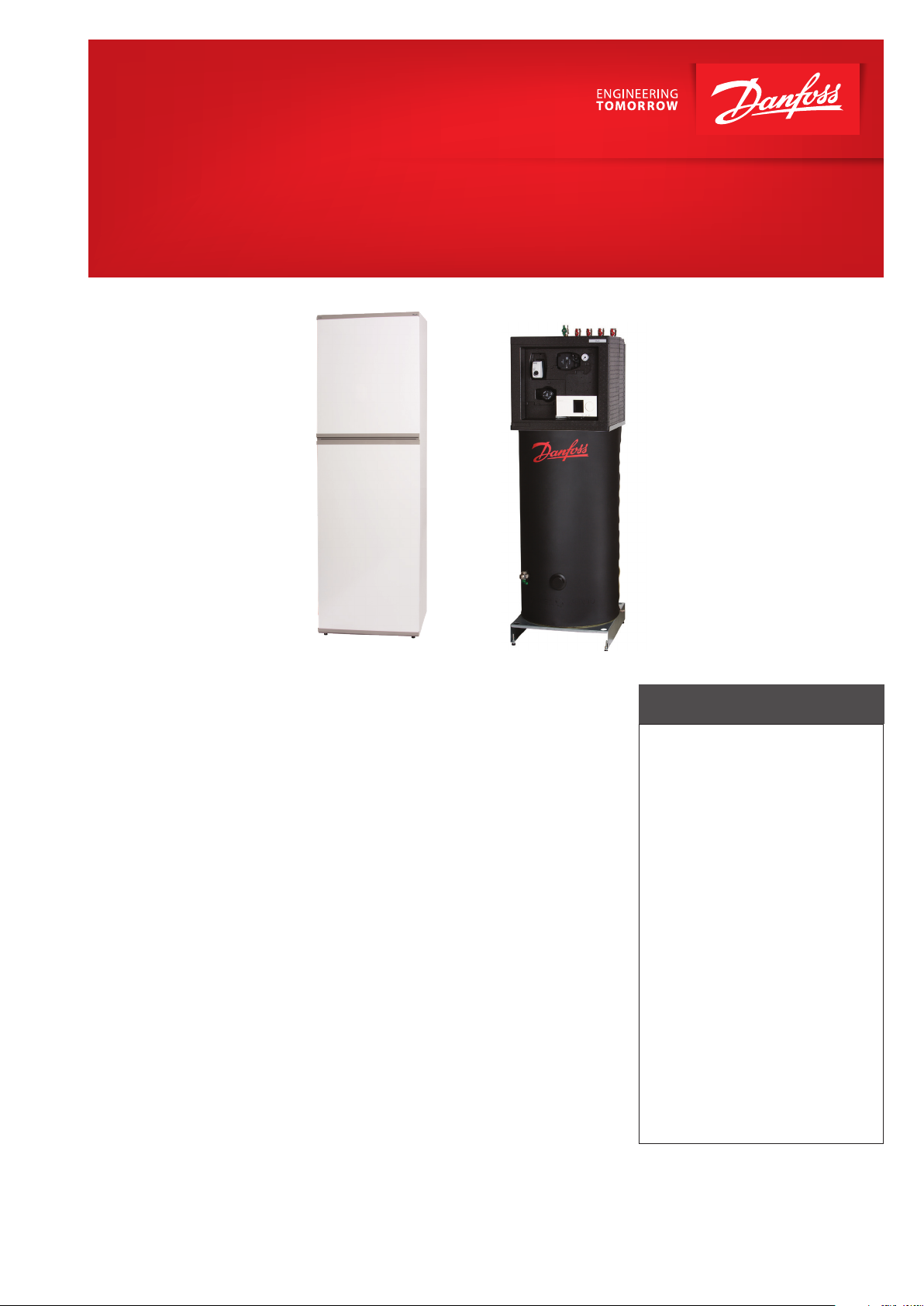
Termix BVX FI RO T/E
Indirect substation for single-family houses or apartments
Application
The Termix BVX FI RO T/E substation
is a complete solution for hot water and space heating with optimal
safety, efficient energy transfer, servicefriendly construction and a compact design. The substation is used
if a heat exchanger is required or on
a conversion to district heating where
the existing equipment is unsuitable
for direct connection.
District heating (DH)
The substation is prefabricated with
a differential pressure controller, fitting
piece and sensor pockets for insertion
of a heat meter as well as strainers and
ball valves.
Heating (HE)
The heating circuit consists of a plate
heat exchanger, safety valves, pressure gauge, ball valves, drain valve,
air valves, expansion vessel and circulation pump. The temperature of the
heating is controlled by an electronic
controller with an outdoor temperature sensor.
Domestic hot water (DHW)
The domestic hot water circuit consists
of a hot water tank with coil and selfacting thermostatic control valve. The DHW
tank and coil are enamelled and the tank
contains a magnesium anode.
Options
The Termix BVX FI RO T/E can be supplied with a thermostatic circulation
valve or a built-in non-return valve.
Option delivered loose with the unit.
Construction
All pipes are made of stainless steel.
The connections are made with nuts
and gaskets. The Termix BVX FI RO T/E
is completed by a white steel cover in
modern design with door. The 105 ltr.
tank can replace the older 150 ltr. tank
thanks to the unit being fully insulated.
This will save space as well. Non-return
valve and safety valve for the cold water
supply is delivered loose with the unit.
FEATURES AND BENEFITS
• Substation for single-family
houses or apartments
• DHW regulation
• Indirect heating with
electronic control
• 105 ltr. tank for DHW
• Capacity: 11-30 kW heating
• Suitable in cases of low
district heating capacity
• Operates independently
of differential pressure
and flow temperature
• Pipes and plate heat exchanger
made of stainless steel
• Minimum space required
for installation
• Fully insulated
www.danfoss.com
Page 2
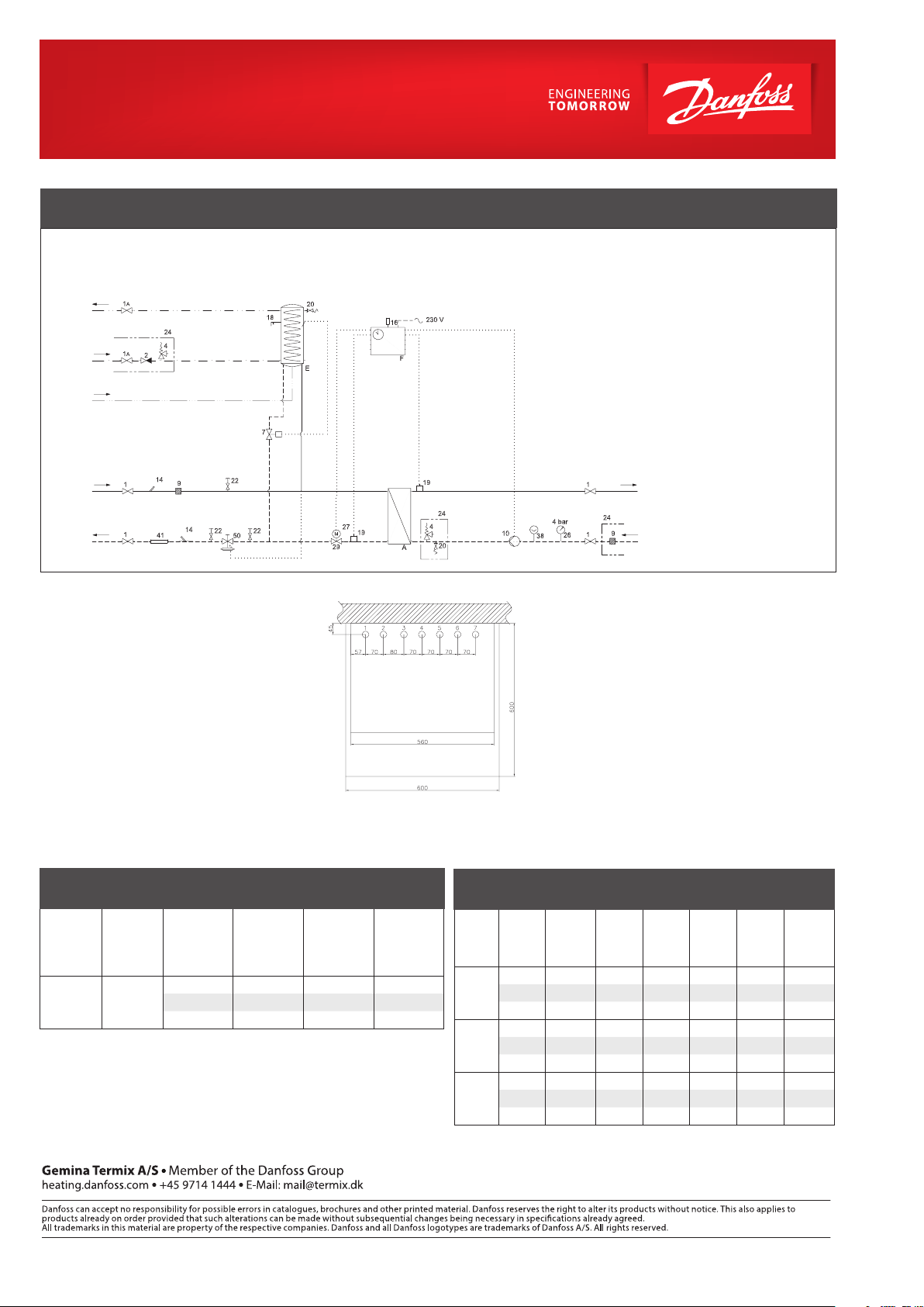
CIRCUIT DIAGRAM EXAMPLE
DHW
DCW
DCW
DH
Supply
DH
Return
Technical parameters:
Nominal pressure: PN 10 (PN16 on request)
Max. supply temperature: T
Brazing material (HEX): Copper
= 120 °C
max
Weight incl. cover: 120 – 150 k g
Cover: White-lacquered
steel sheet
Dimensions (mm):
With cover:
H 1910 x W 600 x D 600
A Plate heat exchanger, HE
E DHW tank with coil
F Electronic controller
1 Ball valve
1A Ball valve, DVGW
4 Safet y valve
7 Thermostatic valve
9 Strainer
10 Circulation pump, HE
14 Sensor pocket, heat meter
16 Outdoor sensor
18 Thermometer
HE
Supply
HE
Return
Connections:
1. DHW Circulation (Circ.)
2. Domestic cold water (DCW)
3. Domestic hot water (DHW)
4. Heating (HE) return
5. Heating (HE) supply
6. District heating (DH) return
7. Distict heating (DH) supply
Connections sizes:
All connection: ¾“ G (int. thread)
Options:
• Thermostatic circulation set
19 Surface sensor
20 Filling / drain valve
22 Test connection
24 Delivered loose with unit
26 Manometer
27 Actuator
29 2 - way motorized valve
38 Expansion tank
41 Fitting piece, heat meter
50 Differential pressure
controller w /o flow limiter
DHW: CAPACITY EXAMPLES, 10 °C / 50 °C
Substation
type
BVX 2-x 105
Tan k
volume
[l]
Coil
supply/return
temp.
[°C]
70/30 272 335 12,7
60/30 199 262 9,3
* Output first hour = constant output + 60% of tank volume
DHW
constant
capacity
[l/h]
The connections are at the
top of the station
DHW
capacity
first hour*
constant
capacity
[l/h]
DHW
[kW]
HEATING: CAPACITY EXAMPLES
Sub-
Heating
station
capacity
type
BVX 2-1
BVX 2-2
BVX 2-3
* Heat meter not included
Supply
mary
[°C]
Heating
circuit
[°C]
flow pri-
[kW]
15 75/45 40/65 35 50 455 543
15 80/50 45/70 35 50 452 544
11 90/51 50/70 35 50 257 499
25 75/45 40/65 45 45 746 904
25 80/50 45/70 45 40 742 908
19 90/51 50/70 45 30 445 868
30 75/45 40/65 50 40 880 1088
30 80/45 45/70 50 40 871 1087
30 90/50 50/70 50 20 699 1363
Pressure
loss
primary*
[kPa]
Residual
pump
head
[kPa]
Flow
rate
Primary
[l/h]
Flow rate
second-
ary l/h
© Danfoss | DHS-SMCT/ PL | 2018 . 09
VL.MP.I1.02
 Loading...