

Page 1
Data Sheet
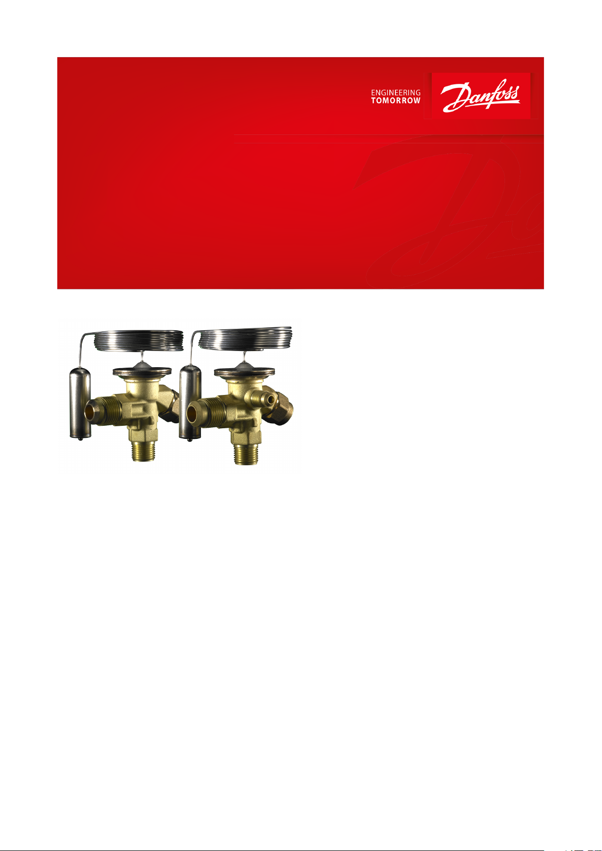
Thermostatic expansion valve
Type T 2 and TE 2
Thermostatic expansion valves maintain a constant
superheat level at the evaporator outlet
Thermostatic expansion valves regulate the
injection of refrigerant liquid into evaporators.
Injection is controlled by the refrigerant
superheat.
Therefore the valves are especially suitable for
liquid injection in ”dry“ evaporators where the
superheat at the evaporator outlet is
proportional to the evaporator load.
AI241486443133en-001401
Page 2

Thermostatic expansion valve, type T 2 and TE 2
Features
• Large temperature range
◦ Equally applicable to freezing, refrigeration and air conditioning applications.
• Interchangeable orice assembly
◦ easy storage
◦ easy capacity matching
◦ better service.
◦ easy cleaning and replacement of lter
• Rated capacities from 1 to 20.5 kW / 0.3 to 5.8 TR for R407C
• Can be supplied with MOP (Max. Operating Pressure).
◦ Protects the compressor motor against excessive evaporating pressure during normal operation
• Stainless steel bulb and Danfoss patented bulb strap
◦ Fast and easy to install
◦ Good temperature transfer from pipe to bulb
• Valves for special temperature ranges can be supplied
• Design protected
© Danfoss | Climate Solutions | 2021.03 AI241486443133en-001401 | 2
Page 3
4
3
1
2
Danfoss
68Z05.14.20
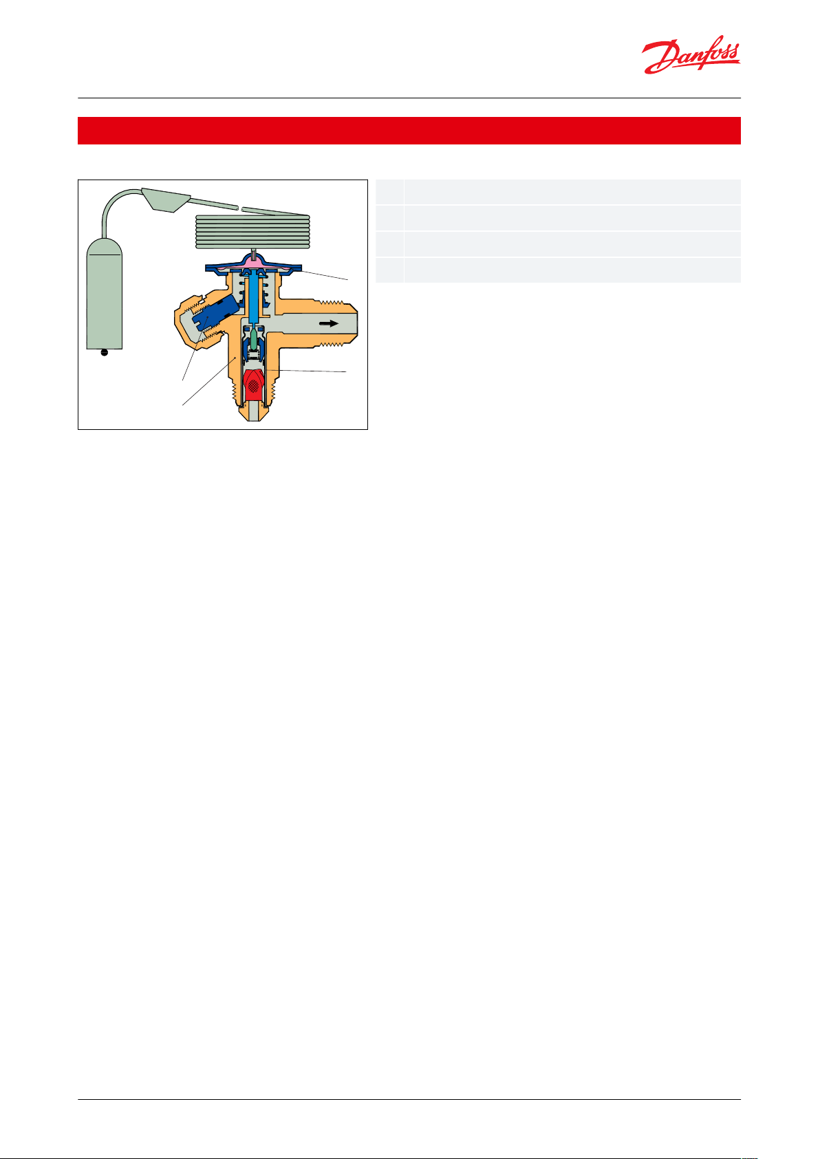
1234Thermostatic element (diaphragm)
Interchangeable orice assembly
Valve body
Superheat setting spindle (see instructions)
Thermostatic expansion valve, type T 2 and TE 2
Functions
Figure 1: Functions
T2 and TE2 valves have an interchangeable orice assembly.
The orice assembly is suitable for all versions of valve body and refrigerants and in all evaporating temperature
ranges.
The charge in the thermostatic element depends on the refrigerant and evaporating temperature range.
The valves are available with internal (T2) or external (TE2) pressure equalization.
External pressure equalization should always be used on systems with liquid distributors. The bulb gives fast and
precise reaction to temperature changes in the evaporator. The bulb is xed with a Danfoss patented bulb strap for
quick, easy and reliable connection. The valves are able to withstand the eects that normally occur with hot gas
defrosting.
To ensure long operating life, the valve cone and seat are made of a special alloy with particularly good wear
qualities.
© Danfoss | Climate Solutions | 2021.03 AI241486443133en-001401 | 3
Page 4
Refrigerant
Range N
-40 °C – 10 °C
Range NM
-40 °C – -5 °C
Range NL
-40 °C – -15 °C
Range B
-60 °C – -25 °C
MOP-point in evaporating temperature te and evaporating pressure p
e
(1)
15 °C / 60 °F
0 °C / 32 °F
-10 °C / 15 °F
-20 °C / -4 °F
R22
100 psig / 6.9 bar (abs)
60 psig / 4.0 bar (abs)
35 psig / 2.4 bar (abs)
20 psig / 1.4 bar (abs)
R407C
95 psig / 6.6 bar (abs)
–––
R134a
55 psig / 3.8 bar (abs)
30 psig / 2.0 bar (abs)
15 psig / 1.0 bar (abs)
–
R404A/R507
120 psig / 8.3 bar (abs)
75 psig / 5.2 bar (abs)
50 psig / 3.4 bar (abs)
30 psig / 2.1 bar (abs)
Orice no.
Rated capacity in tons (TR)
R22
R407C
R134a
R513A
R404A
R507
R407A
R407F
R448A
R449A
R454C
R455A
R1234yf
0X
0.25
0.26
0.19
0.16
0.18
0.25
0.28
0.26
0.25
0.22
0.24
0.1400.51
0.51
0.34
0.29
0.37
0.49
0.56
0.51
0.49
0.42
0.47
0.251110.59
0.51
0.7511.110.97
0.79
0.93
0.4321.3
1.4
0.73
0.6211.3
1.5
1.4
1.311.3
0.5332.3
2.3
1.211.8
2.3
2.6
2.3
2.3
1.8
2.2
0.8843.4
3.5
1.8
1.5
2.8
3.5
4.1
3.6
3.5
2.6
3.3
1.354.8
4.7
2.423.7
4.6
5.4
4.6
4.5
3.4
4.2
1.765.6
5.6
2.9
2.5
4.4
5.6
6.5
5.7
5.5
4.2
5.2
2.1
Thermostatic expansion valve, type T 2 and TE 2
Product specication
Technical data
Max. temperature
Bulb, when valve is installed: 100 °C
Bulb, element not mounted: 60 °C
Min. temperature
T2 – TE2: -60 °C
Max. test pressure
PT = 38 bar
Max. working pressure
PS/MWP = 34 bar
Table 1: Technical data
(1)
(1)
Pe in bar gauge
Pe in bar gauge
Superheat
SS = static superheat
OS = opening superheat
SH = SS + OS = total superheat
Q
= rated capacity
nom
Q
= maximum capacity
max
Static superheat SS can be adjusted with setting spindle.
Standard superheat setting SS is 4K for all standard valves.
The opening superheat OS is 6 K from when opening begins to where the valve gives its rated capacity Q
Example
Static superheat SS = 5 K
Opening superheat OS = 6 K
Total superheat SH = 5 + 6 = 11 K
Table 2: Range N: -40 to 50 °F
nom
.
The rated capacity is based on:
Evaporating temperature te = 40 °F
Condensing temperature tc = 100 °F
Refrigerant temperature ahead of valve tl = 98 °F
© Danfoss | Climate Solutions | 2021.03 AI241486443133en-001401 | 4
Page 5

Orice no.
Rated capacity in kW
R22
R407C
R134a
R513A
R404A
R507
R407A
R407F
R448A
R449A
R454C
R455A
R1234yf
0X
0.9
0.92
0.68
0.58
0.64
0.8810.9
0.88
0.77
0.86
0.4901.8
1.8
1.211.3
1.721.8
1.7
1.5
1.7
0.8713.5
3.5
2.1
1.8
2.6
3.4
3.9
3.5
3.4
2.8
3.3
1.524.7
4.8
2.6
2.2
3.7
4.7
5.4
4.8
4.6
3.6
4.4
1.838
8.1
4.3
3.7
6.389.2
8.1
7.9
6.2
7.6
3.1412.1
12.4
6.4
5.4
9.9
12.4
14.3
12.6
12.1
9.3
11.5
4.6516.7
16.5
8.4
6.91316.31916.3
15.7
11.8
14.7
5.9619.7
19.7
10.1
8.6
15.5
19.6
22.9
19.8
19.1
14.8
18.3
7.3
Valve type
Orice
no.
Cond. temp. [°C]
Evaporating [°C]
-40
-30
-20
-10
T2 / TE2
0X250.76
0.83
0.88
0.9
T2 / TE2000.99
1.21
1.42
1.6
T2 / TE211.41
1.8
2.27
2.77
Subcooling [K]241015
Correction factor
0.98
1
1.07
1.12
Thermostatic expansion valve, type T 2 and TE 2
Table 3: Range N: -40 to 10 °C
The rated capacity is based on:
Evaporating temperature te = 4.4 °C
Condensing temperature tc = 38 °C
Refrigerant temperature ahead of valve tl = 37 °C
Valve selection based on capacity calculation
As for extended capacity calculations and valve selection based on capacities and refrigerants, please refer to
Coolselector®2. Rated and extended capacities are calculated with the Coolselector®2 calculation engine to ARI
standards with the ASEREP equations based on laboratory measurements of selected valves.
How to select a valve
Example:
Refrigerant = R407C
Q (capacity) = 1.1kW
Tcond (condensing temperature) = 25 °C
Tevap (evaporator temperature) = -30 °C
Tsub (subcooling temperature) = 2 K
Dpd (distributer pressure drop) = 1 bar
Q (capacity) = 1.1kW
fsub (subcooling correction factor) = 0.98
fp (distribution correction factor) = 0.96
Q
fsub× fp
0.98 × 0.96
The selection will be: TE2 orice 00 (1.21 kW > 1.17 kW)
Table 4: Capacity in kW, range N -40 °C to 10 °C. Opening superheat sh= 6 K
= selectedcapacity
1.1
= 1.17kW
Table 5: Subcooling correction factor 'fsub'
© Danfoss | Climate Solutions | 2021.03 AI241486443133en-001401 | 5
Page 6

Pressure drop [bar]
Evaporating [°C]
-40
-35
-30
-25
“Pressure drop [bar]”
0111110.96
0.96
0.96
0.96
1.5
0.94
0.94
0.94
0.9420.92
0.92
0.92
0.92
Outlet
Equalization
WeightAB
[kg / lb]
Flare × are
1/2 ” are
1/4 ” are
0.3 / 0.7
Flare × solder
1/2 ” solder
12 mm solder
1/4 ” solder
6 mm solder
0.3 / 0.7
Solder ODF
Weight
[in]
[mm]
[kg / lb]
1/460.05 / 0.11
3/8100.05 / 0.11
Thermostatic expansion valve, type T 2 and TE 2
Table 6: Distributer correction factor 'fp' *
* Calculated at 32 °C condensing temperature
Dimensions and weights
Figure 2: Flare × are (All dimentions are in mm) Figure 3: Flare × solder (All dimentions are in mm)
Table 7: Dimensions and weights
Figure 4: Solder adaptor
Table 8: Solder adaptor
© Danfoss | Climate Solutions | 2021.03 AI241486443133en-001401 | 6
Page 7

T2
TE2N4511A
internal equalization
external equalization
Nordborg, Denmark (BE = Wuqing, China)
week
2011
Monday
Thermostatic expansion valve, type T 2 and TE 2
Identication
Figure 5: Identication
Production place and date N4511A
The thermostatic element has laser engraved data on top of the diaphragm. This engraving gives valve type (with
code number), evaporating temperature range, MOP point, refrigerant, and max. working pressure. PS/MWP.
Figure 6: Orice assembly and lter for are x are version for T2 and TE2
Orice assembly for T2 and TE2
The orice assembly is marked with the orice size (e.g. 06) and week stamp + last number in the year (e.g. 174).
The orice assembly number is also given on the lid of its plastic container.
Figure 7: Capillary tube label for T2 and TE2
Capillary tube label for T2 and TE2
The label gives the orice size (04) and consists of the lid of the orice assembly plastic container. It can easily be
fastened around the expansion valve capillary tube to clearly identify the valve size.
© Danfoss | Climate Solutions | 2021.03 AI241486443133en-001401 | 7
Page 8

Refrigerant
Type
Range
MOP
Pressure equliza‐
tion Flare
Connection are inlet × outlet
Code no. Multi
pack
[°C]
[°C]
[in]
[mm]
R22/R407C
(1)
T2
-40 – 10––
3/8 × 1/2
10×12
068Z3206
T2
-40 – 1015–
3/8 × 1/2
10×12
068Z3208
T2
-40 – -50–
3/8 × 1/2
10×12
068Z3224
T2
-40 – -15
-10–3/8 × 1/2
10×12
068Z3226
T2
-60 – -25––
3/8 × 1/2
10×12
068Z3207
T2
-60 – -25
-20–3/8 × 1/2
10×12
068Z3228
TE2
-40 – 10
–
¼ in / 6 mm
3/8 × 1/2
10×12
068Z3209
TE2
-40 – 10
15
¼ in / 6 mm
3/8 × 1/2
10×12
068Z3211
TE2
-40 – -5
0
¼ in / 6 mm
3/8 × 1/2
10×12
068Z3225
TE2
-40 – -15
-10
¼ in / 6 mm
3/8 × 1/2
10×12
068Z3227
TE2
-60 – -25
–
¼ in / 6 mm
3/8 × 1/2
10×12
068Z3210
TE2
-60 – -25
-20
¼ in / 6 mm
3/8 × 1/2
10×12
068Z3229
R407C
T2
-40 – 10––
3/8 × 1/2
10×12
068Z3496
T2
-40 – 1015–
3/8 × 1/2
10×12
068Z3516
TE2
-40 – 10
–
¼ in / 6 mm
3/8 × 1/2
10×12
068Z3501
TE2
-40 – 10
15
¼ in / 6 mm
3/8 × 1/2
10×12
068Z3517
R134a/R513A
T2
-40 – 10––
3/8 × 1/2
10×12
068Z3346
T2
-40 – 1015–
3/8 × 1/2
10×12
068Z3347
T2
-40 – -50–
3/8 × 1/2
10×12
068Z3393
T2
-40 – -15
-10–3/8 × 1/2
10×12
068Z3369
TE2
-40 – 10
–
¼ in / 6 mm
3/8 × 1/2
10×12
068Z3348
TE2
-40 – 10
15
¼ in / 6 mm
3/8 × 1/2
10×12
068Z3349
TE2
-40 – -5
0
¼ in / 6 mm
3/8 × 1/2
10×12
068Z3392
TE2
-40 – -15
-10
¼ in / 6 mm
3/8 × 1/2
10×12
068Z3370
Thermostatic expansion valve, type T 2 and TE 2
Ordering
T2/TE2 Thermostatic element with bulb strap
Flare x are
Figure 8: Flare x are
Capillary tube: 1.5 m
Range N = -40 – 10 °C
Range B = -60 – -25 °C
Range NM = -40 – -5 °C MOP 0 °C
Range NL = -40 – -15 °C MOP -10 °C
Table 9: Flare x are
© Danfoss | Climate Solutions | 2021.03 AI241486443133en-001401 | 8
Page 9

Refrigerant
Type
Range
MOP
Pressure equliza‐
tion Flare
Connection are inlet × outlet
Code no. Multi
pack
[°C]
[°C]
[in]
[mm]
R404A/R507
T2
-40 – 10––
3/8 × 1/2
10×12
068Z3400
T2
-40 – 1015–
3/8 × 1/2
10×12
068Z3402
T2
-40 – -50–
3/8 × 1/2
10×12
068Z3406
T2
-40 – -15
-10–3/8 × 1/2
10×12
068Z3408
T2
-60 – -25––
3/8 × 1/2
10×12
068Z3401
T2
-60 – -25
-20–3/8 × 1/2
10×12
068Z3410
TE2
-40 – 10
–
¼ in / 6 mm
3/8 × 1/2
10×12
068Z3403
TE2
-40 – 10
15
¼ in / 6 mm
3/8 × 1/2
10×12
068Z3405
TE2
-40 – -5
0
¼ in / 6 mm
3/8 × 1/2
10×12
068Z3407
TE2
-40 – -15
-10
¼ in / 6 mm
3/8 × 1/2
10×12
068Z3409
TE2
-60 – -25
–
¼ in / 6 mm
3/8 × 1/2
10×12
068Z3404
TE2
-60 – -25
-20
¼ in / 6 mm
3/8 × 1/2
10×12
068Z3411
R407F/R407A
T2
-40 – 10––
3/8 × 1/2
10×12
068Z3715
TE2
-40 – 10
–
¼ in / 6 mm
3/8 × 1/2
10×12
068Z3714
R448A/R449A
T2
-40 – 10––
3/8 × 1/2
10×12
068Z3727
TE2
-40 – 10
–
¼ in / 6 mm
3/8 × 1/2
10×12
068Z3728
T2
-40 – -15
-10–3/8 × 1/2
10×12
068Z3675
T2
-60 – -25
-20–3/8 × 1/2
10×12
068Z3735
TE2
-60 – -25
-20
¼ in / 6 mm
3/8 × 1/2
10×12
068Z3736
R454C
T2
-40 – 10-–
3/8 × 1/2
10x12
068Z7483
TE2
-40 – 10
-
¼ in / 6 mm
3/8 × 1/2
10x12
068Z7485
R455A
T2
-40 – 10-–
3/8 × 1/2
10x12
068Z7496
TE2
-40 – 10
-
¼ in / 6 mm
3/8 × 1/2
10x12
068Z7499
R1234yf
T2
-40 – 10-–
3/8 × 1/2
10x12
068Z7487
TE2
-40 – 10
-
¼ in / 6 mm
3/8 × 1/2
10x12
068Z7489
Thermostatic expansion valve, type T 2 and TE 2
(1)
(1)
For R407C plants. Please select valves from the dedicated R407C program
For R407C plants. Please select valves from the dedicated R407C program
Flare x solder
Figure 9: Flare x solder
Capillary tube:1.5 m
Range N=-40 – 10 °C
Range NL = -40 – -15 °C
Range B= -60 – -25 °C
© Danfoss | Climate Solutions | 2021.03 AI241486443133en-001401 | 9
Page 10

Refrigerant
Type
Range
MOP
Pressure equliza‐
tion Flare
Connection are inlet × outlet
Code no. Multi
pack
[°C]
[°C]
[in]
[mm]
R22/R407C
(1)
T2
-40 – 10––
3/8 × 1/2
–
068Z3281
T2
-40 – 10–––10×12
068Z3302
T2
-40 – 1015–
3/8 × 1/2
–
068Z3287
T2
-40 – 1015––10×12
068Z3308
T2
-40 – -15
-10––
10×12
068Z3366
T2
-60 – -25––
3/8 × 1/2
–
068Z3357
T2
-60 – -25–––10×12
068Z3361
T2
-60 – -25
-20–3/8 × 1/2
–
068Z3319
TE2
-40 – 10–¼ in
3/8 × 1/2
–
068Z3284
TE2
-40 – 10–6 mm–10×12
068Z3305
TE2
-40 – 1015¼ in
3/8 × 1/2
–
068Z3290
TE2
-40 – 10156 mm–10×12
068Z3311
TE2
-40 – -15
-10
6 mm–10×12
068Z3367
TE2
-60 – -25–¼ in
3/8 × 1/2
–
068Z3359
TE2
-60 – -25
–
6 mm–10×12
068Z3363
TE2
-60 – -25
-20
¼ in
3/8 × 1/2
–
068Z3320
R407C
T2
-40 – 10–––10×12
068Z3502
T2
-40 – 1015–
3/8 × 1/2
–
068Z3329
T2
-40 – 1015––10×12
068Z3514
TE2
-40 – 10–¼ in
3/8 × 1/2
–
068Z3446
TE2
-40 – 10–6 mm–10×12
068Z3503
TE2
-40 – 1015¼ in
3/8 × 1/2
–
068Z3447
TE2
-40 – 10156 mm–10×12
068Z3515
R134a/R513A
T2
-40 – 10––
3/8 × 1/2
–
068Z3383
T2
-40 – 10–––10×12
068Z3384
T2
-40 – 1015–
3/8 × 1/2
–
068Z3387
T2
-40 – 1015––10×12
068Z3388
TE2
-40 – 10–¼ in
3/8 × 1/2
–
068Z3385
TE2
-40 – 10–6 mm–10×12
068Z3386
TE2
-40 – 1015¼ in
3/8 × 1/2
–
068Z3389
TE2
-40 – 10156 mm–10×12
068Z3390
R404A/R507
T2
-40 – 10––
3/8 × 1/2
–
068Z3414
T2
-40 – 10–––10×12
068Z3435
T2
-40 – 1015–
3/8 × 1/2
–
068Z3416
T2
-40 – 1015––10×12
068Z3423
T2
-40 – -15
-10–3/8 × 1/2
–
068Z3429
T2
-40 – -15
-10––
10×12
068Z3436
T2
-60 – -25––
3/8 × 1/2
–
068Z3418
T2
-60 – -25–––10×12
068Z3425
T2
-60 – -25
-20–3/8 × 1/2
–
068Z3420
T2
-60 – -25
-20––
10×12
068Z3427
TE2
-40 – 10–¼ in
3/8 × 1/2
–
068Z3415
TE2
-40 – 10–6 mm–10×12
068Z3422
TE2
-40 – 10156 mm–10×12
068Z3424
TE2
-40 – 1015¼ in
3/8 × 1/2
–
068Z3417
TE2
-40 – -15
-10
¼ in
3/8 × 1/2
–
068Z3430
TE2
-40 – -15
-10
6 mm–10×12
068Z3437
TE2
-60 – -25–¼ in
3/8 × 1/2
–
068Z3419
TE2
-60 – -25
–
6 mm–10×12
068Z3426
TE2
-60 – -25
-20
¼ in
3/8 × 1/2
–
068Z3421
TE2
-60 – -25
-20
6 mm–10×12
068Z3428
R407F/R407A
T2
-40 – 10––
3/8 × 1/2
–
068Z3716
TE2
-40 – 10–¼ in
3/8 × 1/2
–
068Z3713
Thermostatic expansion valve, type T 2 and TE 2
Table 10: Flare x solder
© Danfoss | Climate Solutions | 2021.03 AI241486443133en-001401 | 10
Page 11

Refrigerant
Type
Range
MOP
Pressure equliza‐
tion Flare
Connection are inlet × outlet
Code no. Multi
pack
[°C]
[°C]
[in]
[mm]
R448A/R449A
T2
-40 – 10––
3/8 × 1/2
–
068Z3729
TE2
-40 – 10–¼ in
3/8 × 1/2
–
068Z3730
T2
-40 – -15
-10–3/8 × 1/2
–
068Z3664
T2
-60 – -25
-20–3/8 × 1/2
–
068Z3737
TE2
-40 – -15
-10
¼ in
3/8 × 1/2
–
068Z3665
TE2
-60 – -25
-20
¼ in
3/8 × 1/2
–
068Z3738
T2
-40 – -15
-10––
10×12
068Z3674
TE2
-60 – -25
-20
6 mm–10×12
068Z3672
R452A
T2
-40 – 10––
3/8 × 1/2
–
068Z3806
TE2
-40 – 10–¼ in
3/8 × 1/2
–
068Z3807
T2
-40 – 10–––10×12
068Z3808
TE2
-40 – 10–6 mm–10×12
068Z3809
R454C
T2
-40 – 10––
3/8 × 1/2
–
068Z7490
T2
-40 – 10–––10x12
068Z7484
TE2
-40 – 10–¼ in
3/8 × 1/2
–
068Z7492
TE2
-40 – 10–6 mm–10x12
068Z7486
R455A
T2
-40 – 10––
3/8 × 1/2
–
068Z7494
T2
-40 – 10–––10x12
068Z7498
TE2
-40 – 10–¼ in
3/8 × 1/2
–
068Z7501
TE2
-40 – 10–6 mm–10x12
068Z7500
R1234yf
T2
-40 – 10––
3/8 × 1/2
–
068Z7491
T2
-40 – 10–––10x12
068Z7488
TE2
-40 – 10–¼ in
3/8 × 1/2
–
068Z7493
TE2
-40 – 10–6 mm-10x12
068Z7495
Connection for copper tubing with outside diameter
Reducer for copper tubing with outside diameter
Code no.
[in]
[mm]
[in]
[mm]
1/46––011L1101
3/810––011L1135
1/212––011L1103––
1/46011L1107
Thermostatic expansion valve, type T 2 and TE 2
(1)
(1)
For R407C plants, please select valves from the dedicated R407C program
For R407C plants, please select valves from the dedicated R407C program
Flare connections
Figure 10: Flare connections
Table 11: Flare connections
Example :
A TE2 thermostatic expansion valve consists of two parts + are nuts if required:
• 1 thermostatic element
• 1 orice assembly and are nuts
When ordering one thermostatic expansion valve, TE2 with orice 01, ve code numbers are required:
• 1-o thermostatic element - 068Z3209
• 1-o orice assembly 01 - 068-2010
• 1-o 3⁄8 in are nut - 011L1135
• 1-o 1⁄2 in are nut - 011L1103
• 1-o 1⁄4 in are nut - 011L1101
© Danfoss | Climate Solutions | 2021.03 AI241486443133en-001401 | 11
Page 12

Danfoss
68Z62.11
Orice no.
Code no.
0X
068-2002
00
068-2003
01
068-2010
02
068-2015
03
068-2006
04
068-2007
05
068-2008
06
068-2009
Danfoss
68z17
Orice
no.
Code no.
0X
068-2089
00
068-2090
01
068-2091
02
068-2092
03
068-2093
04
068-2094
05
068-2095
06
068-2096
Thermostatic expansion valve, type T 2 and TE 2
Orice assembly with lter
Figure 11: Orice assembly with lter
Table 12: Orice assembly with lter
Orice assembly with lter for solder adaptor
Figure 12: Orice assembly with lter for solder adaptor
Table 13: Orice assembly with lter for solder adaptor
© Danfoss | Climate Solutions | 2021.03 AI241486443133en-001401 | 12
Page 13

Filter type
Code no. Multi pack
For are connection
068-0003
For solder adaptor
068-0015
Danfoss
68-8026
Connection ODF solder
Code no.
1⁄4 in
068-2062
6 mm
068-2063
3⁄8 in
068-2060
10 mm
068-2061
Description
Code no.
Filter excl.
orice assembly
068-0015
Thermostatic expansion valve, type T 2 and TE 2
Filter
Figure 13: Filter
Table 14: Filter
Solder adaptor
Figure 14: Solder adaptor
The adaptor is for use with thermostatic expansion valves T2 and TE2 with are × solder connections. When the
adaptor is tted correctly it meets the sealing requirements of DIN 8964.
The adaptor oers the following advantages:
• The orice assembly can be replaced.
• The lter can be cleaned or replaced.
When using the solder adapter, a special orice assembly is required. Please use the following tables to select both
the appropriate adapter and orice asembly.
Only in this way can the sealing requirements of DIN 8964 be fullled.
Solder adaptor for lter drier (FSA) must not be used in the T2 inlet.
Table 15: Solder adaptor without orice assembly and lter
Table 16: Filter for solder adaptor
Bulb strap (Danfoss patented)
Figure 15: Bulb strap
Each valve is delivered with a Danfoss patented bulb strap. Spares can be ordered.
© Danfoss | Climate Solutions | 2021.03 AI241486443133en-001401 | 13
Page 14

Description
Pack mode
Quantity / pack
Code no.
Bulb strap 0.4 mm Max. 28 mm tube
I45068U3505
Bulb strap 0.4 mm Max. 50 mm tube
I45068U3506
Bulb strap 0.4 mm Max. 28 mm tube
M25068U3507
Bulb strap 0.4 mm Max. 50 mm tube
M25068U3508
Thermostatic expansion valve, type T 2 and TE 2
Table 17: Bulb strap (Danfoss patented)
© Danfoss | Climate Solutions | 2021.03 AI241486443133en-001401 | 14
Page 15

File name
Document type
Document topic
Approval_authority
EAC RU Д-DK.БЛ08.В.00191_18
EAC Declaration
Machinery & Equipment
EAC
Danfoss 068U9615.06
Manufacturers Declaration
PED/RoHS
Danfoss
Danfoss 068Z9620.00
Manufacturers Declaration
-
Danfoss
Danfoss 068-9601.00
Manufacturers Declaration
-
Danfoss
UA.089.D.00188-17
UA Declaration
PED
LLC CDC EURO TYSK
UA.TR-089.0993-17
Pressure - Safety Certicate
PED
LLC CDC EURO TYSK
Danfoss 068U9616.01
Manufacturers Declaration
China RoHS
Danfoss
Thermostatic expansion valve, type T 2 and TE 2
Certicates, declarations, and approvals
The list contains all certicates, declarations, and approvals for this product type. Individual code number may have
some or all of these approvals, and certain local approvals may not appear on the list.
Some approvals may change over time. You can check the most current status at danfoss.com or contact your local
Danfoss representative if you have any questions.
Table 18: Certicates, declarations, and approvals
© Danfoss | Climate Solutions | 2021.03 AI241486443133en-001401 | 15
Page 16

Online support
Danfoss oers a wide range of support along with our products, including digital product information, software,
mobile apps, and expert guidance. See the possibilities below.
The Danfoss Product Store
The Danfoss Product Store is your one-stop shop for everything product related—no matter where
you are in the world or what area of the cooling industry you work in. Get quick access to essential
information like product specs, code numbers, technical documentation, certications, accessories,
and more.
Start browsing at store.danfoss.com.
Find technical documentation
Find the technical documentation you need to get your project up and running. Get direct access to
our ocial collection of data sheets, certicates and declarations, manuals and guides, 3D models
and drawings, case stories, brochures, and much more.
Start searching now at www.danfoss.com/en/service-and-support/documentation.
Danfoss Learning
Danfoss Learning is a free online learning platform. It features courses and materials specically
designed to help engineers, installers, service technicians, and wholesalers better understand the
products, applications, industry topics, and trends that will help you do your job better.
Create your Danfoss Learning account for free at www.danfoss.com/en/service-and-support/learning.
Get local information and support
Local Danfoss websites are the main sources for help and information about our company and
products. Find product availability, get the latest regional news, or connect with a nearby expert—all
in your own language.
Find your local Danfoss website here: www.danfoss.com/en/choose-region.
Coolselector®2 - nd the best components for you HVAC/R system
Coolselector®2 makes it easy for engineers, consultants, and designers to nd and order the best
components for refrigeration and air conditioning systems. Run calculations based on your operating
conditions and then choose the best setup for your system design.
Download Coolselector®2 for free at coolselector.danfoss.com.
Danfoss can accept no responsibility for possible errors in catalogues, brochures and other printed material. Danfoss reserves the right to alter its
products without notice. This also applies to products already on order provided that such alterations can be made without subsequential
changes being necessary in specications already agreed. All trademarks in this material are property of the respective companies. Danfoss and
the Danfoss logotype are trademarks of Danfoss A/S. All rights reserved.
© Danfoss | Climate Solutions | 2021.03 AI241486443133en-001401 | 16
 Loading...