

Page 1
Data sheet
TDU.5 floor distribution unit
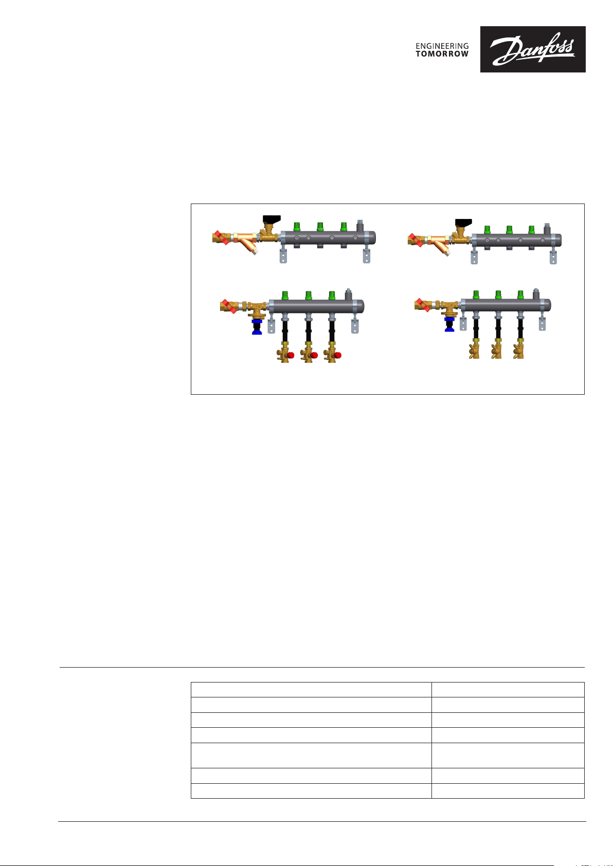
General description
and application
Typ e 1 Typ e 2
General operating
parameters
The TDU.5 floor distribution unit is intended
for two pipe horizontal heating systems and
includes connecting, measuring, regulating and
distribution functions.
The TDU.5 is easily installed on the wall surface
and connected to the riser of heating system.
The apartment horizontal heating systems are
connected to the branches of the unit. Design of
the TDU.5 provides convenient access to all the
elements thus simplifies system adjustment.
The TDU.5 floor distribution units are
manufactured with 2–6 circuits
(left-hand / right-hand versions).
All manifolds are factory insulated with 13 mm
elastomeric insulation.
Design temperature °C 95
Design pressure bar 10
Test pressure, bar 16
Maximum differential pressure in the risers bar 1,5
Setting of differential pressure in the apartment
heating system kPa
Connection to the risers (3 variants) Rp ¾; Rp 1; Rp 1¼
Connection to heating system of apartments Rp ½ – return line
Standard TDU.5 consists of:
On main manifolds DN50
• Automatic balancing valve – differential
pressure controller ASV-PV
• Partner valve with flow limitation
function ASV-BD
• Strainer
• Shut-off valves
• Drain
• Deairing
On branches DN15:
• Heat meter inserts for each apartment
• Type 1: Manual balancing valves USV-I
• Type 2: Control balancing valves RA-HC
The TDU.5 floor distribution units are
manufactured with 2–6 circuits
(left-hand / right-hand versions).
Accessories:
• Cabinets
• TWA actuators for RA-HC
• Room thermostats
• Energy meters
5 – 25
© Danfoss | 2021.09
AI378433154991en-010103 | 1
Page 2
Data sheet TDU.5 floor distribution unit
Designation
Code numbers
Typ e 1
Code Designation
152F0275 TD U.5 2L-20-AS VBD15-A SVPV15-USV I15 2 left RP ¾” 15 USV-I
152F0276 TDU.5 3L-25-ASVBD20-ASVPV20-USVI15 3 left RP 1” 20 USV-I
152F0277 TDU.5 4L-25-ASVBD20-ASVPV20-USVI15 4 left RP1” 20 USV-I
152F0278 TDU.5 4L-32-ASVBD25-ASVPV25-USVI15 4 left R P 1¼” 25 USV-I
152F0279 TDU.5 5L-32-ASVBD25-ASVPV25-USVI15 5 left R P 1¼” 25 USV-I
152F0280 TDU.5 6L-32-ASVBD25-ASVPV25-USVI15 6 left RP 1¼” 25 USV-I
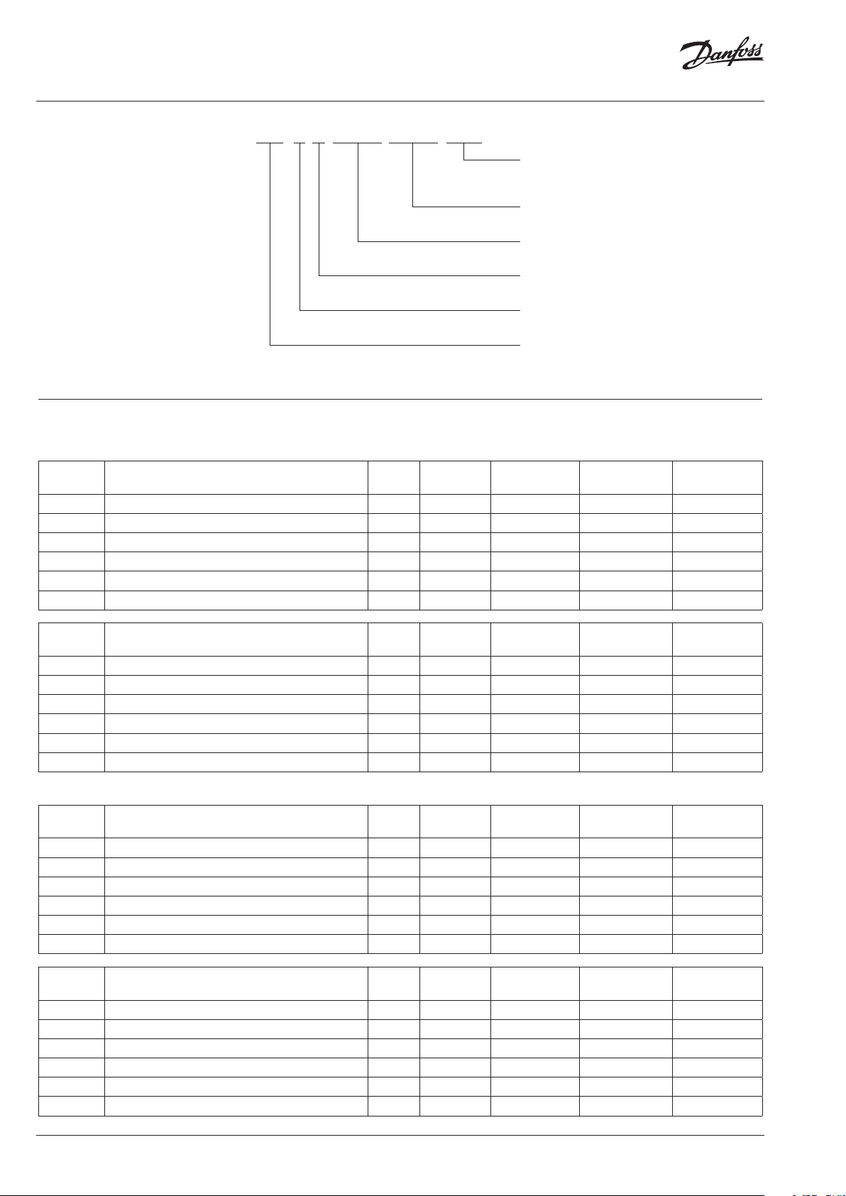
TDU.5 - 4L - 25 - ASVBD20 - ASVPV 20 - USVI15
Circuits
Execution
Balancing in each circuit
USVI15 – manual balancing valve
RAHC15 – control balancing valve
Automatic balancing valve
ASPV15; ASPV20; ASPV25
Partner valve
ASVBD15; ASVBD20; ASVBD25
Connection to risers
(20 – RP ¾; 25 – RP 1; 32 – RP 1¼)
Execution (L – left-hand / R – right-hand)
Number of circuits (from 2 to 6)*
Floor distribution units generation (TDU.5)
* more circuits are available on request
Connection
to risers
DN ASV-PV /
ASV-BD
Branch
Code Designation
152F0281 TDU.5 2R -20 -ASV BD15-AS VPV15 - USVI15 2 right RP ¾” 15 USV-I
152F0282 TDU.5 3R-25-ASVBD20-ASVPV20-USVI15 3 right RP 1” 20 USV-I
152F0283 TDU.5 4R-25-ASVBD20-ASVPV20-USVI15 4 right RP1” 20 USV-I
152F0284 TDU.5 4R-32-ASVBD25-ASVPV25-USVI15 4 right RP 1¼” 25 USV-I
152F0285 TDU.5 5R-32-ASVBD25-ASVPV25-USVI15 5 right R P 1¼ ” 25 USV-I
152F0286 TDU.5 6R-32-ASVBD25-ASVPV25-USVI15 6 right R P 1¼” 25 USV-I
Typ e 2
Code Designation
152F0287 TD U.5 2L-20-AS VBD15-A SVPV15-RAHC15 2 left R P ¾” 15 RA-HC
152F0288 TDU.5 3L-25-ASVBD20-ASVPV20-RAHC15 3 left RP 1” 20 RA-HC
152F0289 TDU.5 4L-25-ASVBD20-ASVPV20-RAHC15 4 left RP1” 20 RA-HC
152F0290 TDU.5 4L-32-ASVBD25-ASVPV25-RAHC15 4 left R P 1¼” 25 RA-HC
152F0291 TDU.5 5L-32-ASVBD25-ASVPV25-RAHC15 5 left RP 1¼” 25 RA-HC
152F0292 TDU.5 6L-32-ASVBD25-ASVPV25-RAHC15 6 left RP 1¼” 25 RA-HC
Code Designation
152F0293 TDU.5 2R-20-ASV BD15 -ASV PV15-RAHC15 2 right RP ¾” 15 RA-HC
152F0294 TDU.5 3R-25-ASVBD20-ASVPV20-RAHC15 3 right RP 1” 20 RA-HC
152F0295 TDU.5 4R-25-ASVBD20-ASVPV20-RAHC15 4 right RP1” 20 RA-HC
152F0296 TDU.5 4R-32-ASVBD25-ASVPV25-RAHC15 4 right RP 1¼” 25 RA-HC
152F0297 TDU.5 5R-32-ASVBD25-ASVPV25-RAHC15 5 right R P 1¼ ” 25 RA-HC
152F0298 TDU.5 6R-32-ASVBD25-ASVPV25-RAHC15 6 right R P 1¼” 25 RA-HC
Circuits
Circuits
Circuits
Execution
Execution
Execution
Connection
to risers
Connection
to risers
Connection
to risers
DN ASV-PV /
ASV-BD
DN ASV-PV /
ASV-BD
DN ASV-PV /
ASV-BD
Branch
Branch
Branch
2 | © Danfoss | 2021.09
AI378433154991en-010103
Page 3
Data sheet TDU.5 floor distribution unit
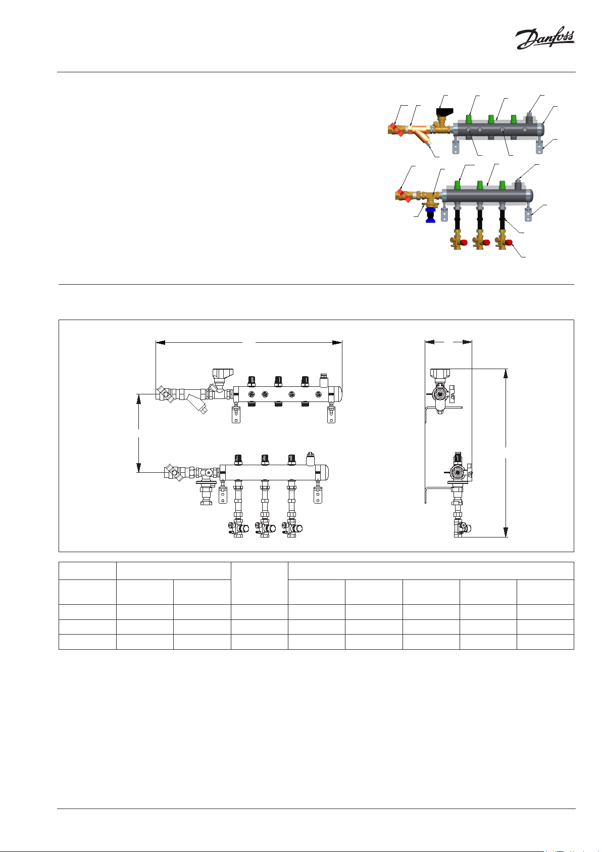
Construction Ball valve with fitting.
1. Shut-off valve
2. Strainer
3. Partner valve ASV-BD
4. Manifold
5. Shut-off valve
6. Automatic balancing valve ASV-PV.
7. Drain valve
8. Clamp
9. Insert for heat meter DN15, L=110 mm.
10. Balancing valve (USV-I/RA-HC)
11. Manual air vent
12. Drain valve
13. Fitting for impulse tube connection. (In case
there is no partner valve)
14. Fitting for temperature sensor connection
15. Insulation
Dimensions
W
1
1
6
3
2
7
12
5
15
13
5
14
15
11
4
8
11
8
9
10
D
*200 mm.
DN Height H, mm *
insret
group
Left
connection
connection
Right
Maximum
depth D,
mm *
Maximum width W, mm * (depending on number if circuits)
2 3 4 5 6 **
20 533 533 177 568 668 768 868 968
25 536 536 177 597 697 797 897 997
32 539 539 188 640 740 840 940 1040
* Overall dimensions in width, depth and height depend on the installation position.
It is allowed to mount the unit without a casing with the collectors displaced vertically and
horizontally within the length of the ASV-PV impulse tube, while maintaining the possibility
of its mounting and dismounting (impulse tube length is 1.5m). The minimum recommended
vertical distance between manifolds is 200 mm.
** More circuits are available on request
H
AI378433154991en-010103
© Danfoss | 2021.09 | 3
Page 4

Data sheet TDU.5 floor distribution unit
Accessories
Cabinets for TDU5
990
DN of
ASV-PV
W
Maximum
height H,
mm
Maximum
depth D,
mm
Maximum width W, mm (depending on number if circuits)
2 3 4 5 6 **
200
15 990 200 750 750 750 850 1000
20 990 200 750 750 850 1000 1000
25 990 200 750 750 850 1000 130 0
Code Execution
Dimensions
H × W × D mm
152F0335 On-wall 990 × 750 × 200
152F0336 On-wall 990 × 850 × 200
152F0337 On-wall 990 × 1000 × 200
152F0339 On-wall 990 × 1300 × 200
** More circuits are available on request
4 | © Danfoss | 2021.09
AI378433154991en-010103
Page 5

Data sheet TDU.5 floor distribution unit
Automatic balancing valves ASV
Design
1. Spring guide
2. Shut-off handle
3. Spring
4. Differential pressure setting
spindle
5. Setting scale
6. O-ring
7. Locking ring
8. Impulse tube connection
9. Diaphragm element
10. Control diaphragm
11. Internal connection
12. Valve body
13. Pressure-relieved valve cone
14. Seat
ASV handling video
Typ e DN
15 1,6 Rp ½
ASV-PV is a compact differential pressure
controller designed to guarantee
high quality of automatic balancing. Innovative
construction and ease of use are incorporated
into the valve with the following features:
• integrated membrane part into valve body
(12) ,
• easy setting with locking function (7),
• flushing function,
• shutt-off function, separated from presetting
• membrane adapted to valve size.
Via an internal connection and together with
the reference spring (3), pressure in the return
pipe acts on the lower side of the control
diaphragm (10) while via an impulse tube (8),
pressure in the flow pipe acts on the top of
the diaphragm. In this way the balancing valve
maintains adjusted differential pressure.
The valves factory set to 30 kPa. They can be
easily adjusted to another setting using setting
scale (5). Turning the setting ring clockwise
increases the setting; turning it counter clockwise
reduces the setting.
k
[m3/h]
vs
Connection
p setting
range [kPa]
Code no.
003Z5501
20 2,5 Rp ¾ 003Z5502
25 4,0 Rp 1 003Z5503
ASV-BD shut-off valve, multifunctional partner
valve (shut-off, rotating measuring station)
Typ e DN
k
[m3/h]
vs
Connection Code No.
15 3,0
20 6,0 Rp ¾ 003Z4042
internal
thread
25 9,5 Rp 1 003Z4043
Manual balancing
valve USV-I
003Z 2131
Design USV-I
USV valves are designed for manual hydronic
balancing of heating and cooling systems. USV-I
(red knob) is used to limit the flow in heating or
cooling installation or can work separately as
1. Shut-off knob
2. Shut-off spindle
3. Setting spindle
4. Scale disc
5. O-ring
6. Valve cone
7. Valve body
5 – 25
Rp ½ 0 03Z40 41
manual balancing valves for flow limitation. If
certain pipe sectors do not require a control of
differential pressure, USV-I can be used as shutoff- and measuring valve.
AI378433154991en-010103
For USV-I adjustment please consult product data sheet.
© Danfoss | 2021.09 | 5
Page 6

Data sheet TDU.5 floor distribution unit
Control valve RAHC
Description
Accesories:
TWA actuators for RAHC
The RA-HC is a control valve applied together
with Danfoss electronic controls.
Combined with Danfoss thermo actuators (TWA)
the RA-HC valves provide On / Off control, control
the flow over the terminal unit and maintain
optimum temperatures based on room load
requirements.
RA-HC valves have eight presettings, thus the
correct quantity of water flow is ensured for each
circuit.
Typ e
DN 15 G ½ no 16 1,8 −10 ... 100 003Z3932
* The max. differential pressure specified is the maximum pressutre at which the valves give
satisfactory regulation. As with any device which imposes a pressure drop on the system, noise
may occur under certain flow / pressure conditions.
For RA-HC adjustment please consult product data sheet.
manual shut off knob – 013G330 0
Connection
(*)
Typ e
TWA-A NC
TWA-A NO 08 8 H3111
TWA-A NC
TWA-A NO 088 H 3113
Test plugs
Connection
type
RA
RA-HC matches high flow capacities and with its
compact design only little installation space is
required.
The RA-HC with TWA
• Balancing and control function
• High flow capacity
• Compact design, requires
small installation space
• Easy presetting, no tools required
• Shut-off (for isolation during system
maintenance) using manual shut off knob.
Max.
working
pressure
Supply
voltage
24V
AC / DC
230V
AC
Max. diff.
Pressure
with TWA-A
Code No.
08 8 H3110
08 8 H3112
Medium
temp.
(°C)
Code No.
6 | © Danfoss | 2021.09
AI378433154991en-010103
Page 7

Data sheet TDU.5 floor distribution unit
Accesories:
Room thermostats
RET1000
Smart Room
Thermostat
087N6450
RET1000 Smart Room Thermostats combine
sleek modern design with high performing
energy saving control. Chrono-proportional
control significantly improves comfort and
generally improves boiler efficiency by
optimising water temperature.
• Selectable Chrono Proportional
or On/Off control
• User Set Upper
and Lower Temperature Limits
• Output On Indication
• Power Indication
TPOneTM Series
Programmable
Room
Thermostat
087N7851
Danfoss Icon™
Programmable
TPOne Programmable Room Thermostat
platform delivers new levels of user friendly
interaction.
Additional TPOne features include:
• Seperate User & Installer Setting Menus
• Holiday Scheduler
• Upper and Lower Temperature Limits
• Capacitive Touch Button Control
• Push Button Lock
• °C or °F Selectable Display
• Audible Button Click (selectable)
• Frost Protect Temperature Setting
• Selectable Domestic Hot Water Channel
(Mains Variant only)
• Clear Text Display (7 Languages)
• External Sensor/Window Switch input
• Boiler Service Timer
Danfoss Icon™ is a range of flush and surface
mounted room thermostats for hydronic
floor
heating applications.
Features
• Accurate PWM-control
• Compatible with 3’rd party wall frames
• Shine through display with mode keys
• 7 pre-defined schedules and forecast
• Range limitation via user menu
• Neutral design and simple user interface
• Frost protection setting
• Can be used with 230V NC or NO
actuators
• Can be optimized for different
heatsources via service menu
• Valve exercise feature
• Can be used in systems with cooling
• Has input for global setback
• Can be used with floor sensor (optional)
• Very high UV-resistance
AI378433154991en-010103
© Danfoss | 2021.09 | 7
Page 8

Data sheet TDU.5 floor distribution unit
T
ar
f
c
a
d
Accesories:
SonoSelect 10 and
SonoSafe 10 Energy Meters
he Danfoss SonoSelect 10 and SonoSafe 10
e ultrasonic compact energy meters intended
or measuring energy consumption in heating,
ooling and combined heating and cooling
pplications for billing purposes. The meters are
The energy meters consist of an ultrasonic flow
sensor, a pair of Pt1000 temperature sensors
and a calculator with integrated circuits for
temperature measurement, flow calculation and
energy calculation.
esigned for remote meter read-out (AMR).
Feature highlights:
• Proven ultrasonic measuring principle designed for long operating life time
• No calming section or inlet/outlet restrictions
• Low pressure drop down to 0.03 bar at q
• Large 85 x 35 mm LCD display with 8 digits (11.5 mm high), guiding menu and info panel
• Compact design
• Extensive change and error log
• Memory: 4 years of data, yearly and monthly values stored (incl. pulse input)
• Upgradable with communication modules in bracket (dual M- Bus, connection with water meter)
• Power supply 3.6V battery (replacable) or 230V mains power
• Communication baud rate 300, 2400, 4800 and 9600 bps
• SonoApp usable for Android (Bluetooth LE via dongle)
Special
features:
Batter y • 16 + 1 years batter y life (from production date) • 10 + 1 years battery life
Flexibility
Safety
SonoApp
SonoSelect 10 SonoSafe 10
• Heating or cooling or combined heating and cooling
• Supply and return can be configured on site
• Energy units can be configured on site
• Slot for communication upgrade
• 1.5m PUR or silicone cable between calculator and flow
sensor allow for flexible installation, e.g. in flat stations
• EN1434 class 2 + flow and energy calculated every 0.5
second
• Tamper monitor sets alarm if meter is opened by
unauthorized personnel
• Diagnostic function to secure confidence in meter data
• IP65 calculator
• Reverse flow indication
• Installer tool (Guides and configure e.g. AMR, Pulse, units,
supply/return)
• Commissioning tool (Link location to s
• Operation tool (walk by + diagonstics)
p
• Heating
erial number)
• Energy units can be configured on site
• Slot for communicatio
• 0.5 m cable PVC between calculator and
flow sensor
• EN1434 class 2 + flow and energy calculated
every 2 seconds
• IP54 calculator
• Installer tool (Guides and configure e.g.
AMR, Pulse, units)
• Operation tool (walk-by)
• Commissioning tool (Link location to serial
number)
n upgrade
8 | © Danfoss | DCS-SGDPT/PL | 2021.09
AI378433154991en-010103
 Loading...