

Page 1

Data sheet
Standard JIP™ ball valves (PN 16, 25, 40)
Description
Danfoss Standard JIP™ ball valves is a range
of reduced bore shut off valves developed for
District Heating and District Cooling networks,
with circulating medium.
It is a range of steel ball valves with fully welded
body.
The valve design makes them ideal for building
installation due to:
• Energy saving: with optimum flow design
valves have highest kv on the market and
consequently lowest pump energy costs.
• Long lifetime and optimal tightness due to
design and material selection in ball seal and
stem seal (carbon reinforced PTFE) ;
• The valves are maintenance free, besides the
shut off valves in the core distribution network
Danfoss offers a range of supplementary
valves, e.g. hot tap valves, branching valves,
twin valves and draining valves.
Main data:
• DN 15-600
• kVS = 8-26.300 m3/h
• PN 16 / 25 / 40
• Leakage rate A (according to EN12266-1) both directions
• Temperature: 0 ... 180 °C
• Medium: Circulation water / glycolic water up
to 50 %
• Min. storage and transport temperature: −40 °C
Approvals and norms:
• 100 % final inspection. Leak and shell test as
well as dimension and functionality test is
performed on each and every valve according
to applicable standard (EN 12266 part 1
P10-P11-P12 & part 2 F20).
• PED Directive 2014/68/EU Modul H1
• Danfoss A/S is certified according to ISO 9001
• Furthermore certified according to ISO 14001
and ISO45001.
© Danfoss | 2021.08 AI144586457954en-011102 | 1
Page 2

Data sheet Standard JIP™ ball valves
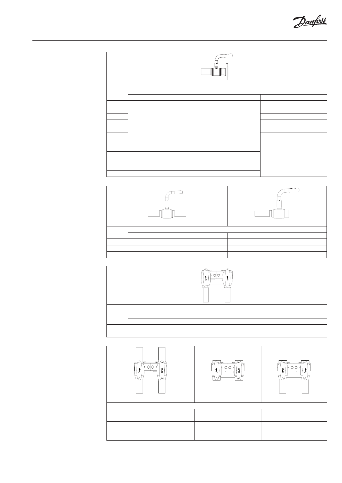
Ordering
JIP-WW welding
JIP-FF flange
JIP-WW welding JIP-FF flange
DN
(mm)
15
20 065 N0105 20 065N0305
25 0 65N 0110 25 065 N0310
32 0 65 N0115 32 065 N0315
40 065 N0120 40 065N0320
50 06 5N0125 50 065N0325
65 065N4280
80 065N4285 80 065N4287 065N4286
100 065N0140 100 065N0240 065N0340
125 0 65N0 745 125 065N0845 065N0945
150 065N0750 150 065N0850 065N0950
200 065N0755 200 0 65N0855 065N0955
WW PN 25 WW PN 40
-
(mm)
06 5N11 00 15
-
Code No.
DN
65 065N4282 065N4281
FF PN 16 FF PN 25 FF PN 4 0
- -
06 5N11 01
-
JIP-II internal thread
JIP-IW internal thread/welding
JIP-WW welding JIP-FF flange
DN
(mm)
65 065N0134 06 5N0132 065N0223 065N 0232 065N03 31 065N0332
80 065 N0139 0 65N013 7 065N0236 065N 0237 065N0336 065N0337
100 065 N0144 0 65N0142 065N0243 065N0242 065N0341 065N0342
125 06 5N014 6 0 65N0147 065N0246 0 65N0247 065N0346 065N0347
150 06 5N0151 0 65N015 2 065 N0251 065N0252 065N 0351 065N0352
200 065N 0156 0 65N0157 065 N0275 065 N0257 065N0356 065N0357
250 065N 0161 065N0162 065N0216 065N0262 065N 0361 065N0362
300 065N016 6 06 5N0167 065N0266 0 65N0267 065N0366 065N0367
350 0 65N0 171 065N0172 0 65N0271 065N 0272 065N0371 065N0372
400 065 N0176 0 65N 0177 065N 0276 065N 0277 0 65N0376 065N0377
450 06 5N0178 0 65N0 179 065N0278 065N0279 0 65N0378 065N0379
500 065 N0181 065N 0182 0 65N0281 065N0282 065N0381 065N0382
600 065N 0186 0 65N0187 -
Code No. W W PN 25 Code No. FF PN 16 Code No. FF PN 25
Valve with
worm gear
Valve with
gear flange
Valve with
worm gear
Valve with
gear flange
Valve with
worm gear
Valve with gear
flange
JIP-II internal thread JIP-IW internal thread / welding
DN
(mm)
L-handle high stem T-handle low stem L-handle high stem T-handle low stem
15 065N0800 065N0802 15 065N0900 065N0904
20 065N0805 065N08 07 20 065N09 05 065N0908
25 065N 0810 06 5N0812 25 0 65N0910 06 5N0914
32 065N 0815
50 065N0825 50 0 65N0925
Code No. II PN 40
DN
(mm)
32 065N0 915
-
Code No. IW PN 4 0
-40 065N0820 40 065N0920
2 | AI144586457954en-011102 © Danfoss | 2021.08
Page 3
Data sheet Standard JIP™ ball valves
Ordering
JIP-FW flange/welding
DN
(mm)
15
20 065N0705
25 065 N0710
32 0 65N07 15
40 065N0720
50 065N0725
65 065N4284 065N4283
80 065N4289 065N4288
100 065N0540 065N0640
125 065N0960 065N 0975
150 065N0965 065N0980
200 065N0970 065N0985
Copper valves
JIP-CC copper
JIP-IC internal thread /copper
Max temp. 130°
PN 16 PN 25 PN 40
JIP-FW flange / welding
Code No.
06 5N11 02
-
-
Copper twin valves for single
pipe connection
JIP-IC internal thread / copper
Max temp. 130°
Twin valves for single pipe
connection
T-handle (DN 15-25) or
L-handle (DN 32)
JIP- WW welding
JIP-II internal thread
JIP IW internal thread / welding
JIP-CC copper JIP-IC internal thread / coppe r
DN
(mm)
15 065N4058 065N4 057
20 065N4067 065N4064
25 065N4095 065N4 087
DN
(mm)
15 065N4195
20 065N4071
CC PN 16 IC PN 16
JIP-IC internal thread / coppe r
Code No.
Code No.
IC PN 16 with T-han dle
JIP-WW welding JIP-II internal thread JIP-IW internal thread / welding
DN
(mm)
15 065N 4001 0 65N08 01 065 N0901
20 065N4002 065N0806 065N0906
25 065N4 003 0 65N 0811 0 65 N09 11
32 065N4004 0 65N0 816 0 65N0 916
WW PN 40 II PN 40 IW PN 40
Code No.
AI144586457954en-011102 | 3© Danfoss | 2021.08
Page 4
Data sheet Standard JIP™ ball valves
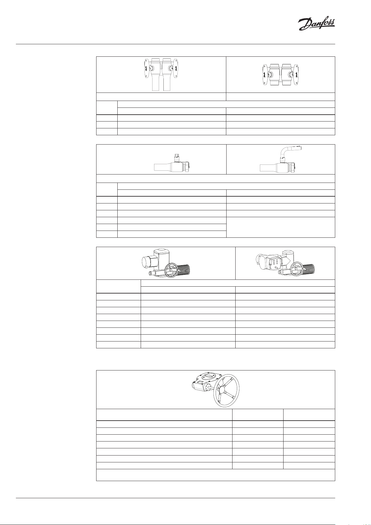
Ordering
Twin valves for double pipe
connection
T-handle
JIP-IW internal tread / welding
JIP-II internal thread
JIP-IW internal thread / welding JIP-II internal thread
DN
(mm)
15 065N7032 065N7022
20 065N7034 065N7024
25 065N7036 065N7026
Draining valves
JIP-WE cc welding/external
thread with closing cap
DN
(mm)
15 065N4322 065N4422
20 065N4323 065N4423
25 065N4324 065N4424
32 065N4325
40 065N4326
50 065N4327
WE PN 40- hex vers. WE PN 40- L-handle
Code No.
IW PN 40 II PN 40
JIP-WE cc welding / external thread with closing cap
Code No.
-
Actuators
Worm gear
DN
(mm)
65 065N8397 065N8398
80 065N 8199 065N8399
100 065N8200 065N8400
125 -200 065N8205 065N8405
250 065N8220 065N8420
300 -350 065N8225 065N8425
400 065N8235 065N8435
450-600 065N8240 065N8440
1)
More information on page 15. For additional information related to the electric actuator ordering, please contact local
Auma NORM
1)
Code No.
Auma MATIC
1)
Danfoss representative.
Description Worm gear
Worm gear for DN 65 reduced bore 065N0683 065N0694
Worm gear for DN 80-100 reduced bore 065N0684 065N0695
Worm gear for DN 125-200 reduced bore 065N0685 065N0695
Worm gear for DN 250 reduced bore 065N0691 065N0696
Worm gear for DN 300-350 reduced bore 065N0687 065N0697
Worm gear for DN 400 reduced bore 065N0688 065N0698
Worm gear for DN 450-600 reduced bore 065N0689 065N0699
Position indicator: Temperature -15 ... 80°C, IP65
Worm gear: Temperature -20 ... 120°C, IP68
Position indicator with
end switch
4 | AI144586457954en-011102 © Danfoss | 2021.08
Page 5
Data sheet Standard JIP™ ball valves
Ordering
Accessories
Replacement handles
Type of handle Fixation Code No.
T Alu. DN 15-25 spring pin 065N8255
L Steel DN 15-32 with plastic grip spring pin 065N8256
L Steel DN 40 -50 with plastic grip spring pin 065N8257
L Steel DN 65 with plastic grip spring pin 065N8258
L Steel DN 80 with plastic grip spring pin 065N8259
L Steel DN 100 with plastic grip spring pin 065N8262
L Steel DN 125 with plastic grip spring pin 065N8260
L Steel DN 150 with plastic grip spring pin 06 5N82 61
L Steel angled DN 200 with plastic grip screw 065N80 01
Handles with extended shaft for pipes with thick insulation
Type of handl e Code No. Valve DN H h S Picture
15 142 19 6 115
Handle DN15-32 RB L115-H 065N8350
Handle DN 40-50 RB L157-H 065N8351
Handle DN 65 RB L205-H 065N8352 65 188 283 205
Handle DN 80-100 RB L405-H 065N8353
Handle DN 125 RB L505-H 065N8354 125 225 412 505
Handle DN 150 RB L645 -H 065N8355 150 2 31 451 645
Handle DN200RB L645-HexT-H 065N8356 200 245 492 645
1)
Valid for flang ed version (FF)
20 142 196 115
25 14 2 (157)1)199 (214)1)115
32 141 (155)1)204 (218)1)115
40 170 ( 201)1)248 (279)1)157
50 174 (20 0)1)252 (284)1)157
80 210 334 405
100 227 367 405
S
H
h
Marking knobs for handles DN15-100 (red/blue) Code No.
Red knobs (bag with 100 pieces) 065N8303
Blue knobs (bag with 100 pieces) 065N8304
Technical data
DN [mm]
KVS [m3/h]
PN
Temp range
Medium
*KVS for the codes 0 65N1100, 065N1101 and 065N1102 is 8 [m3/h], KVS for all other D N 15 codes is 11 [m3/h]
15 20 25 32 40 50 65 80 100 125 15 0 200 250 300 350 400 450 500 600
8/ 11* 15 34 52 96 184 200 470 640 1,080 1,900 2,300 5,10 0 9,10 0 7,000 10,400
16/2 5/40 16/2 5
0-180 °C
Circulation water / glycolic water up to 50 %
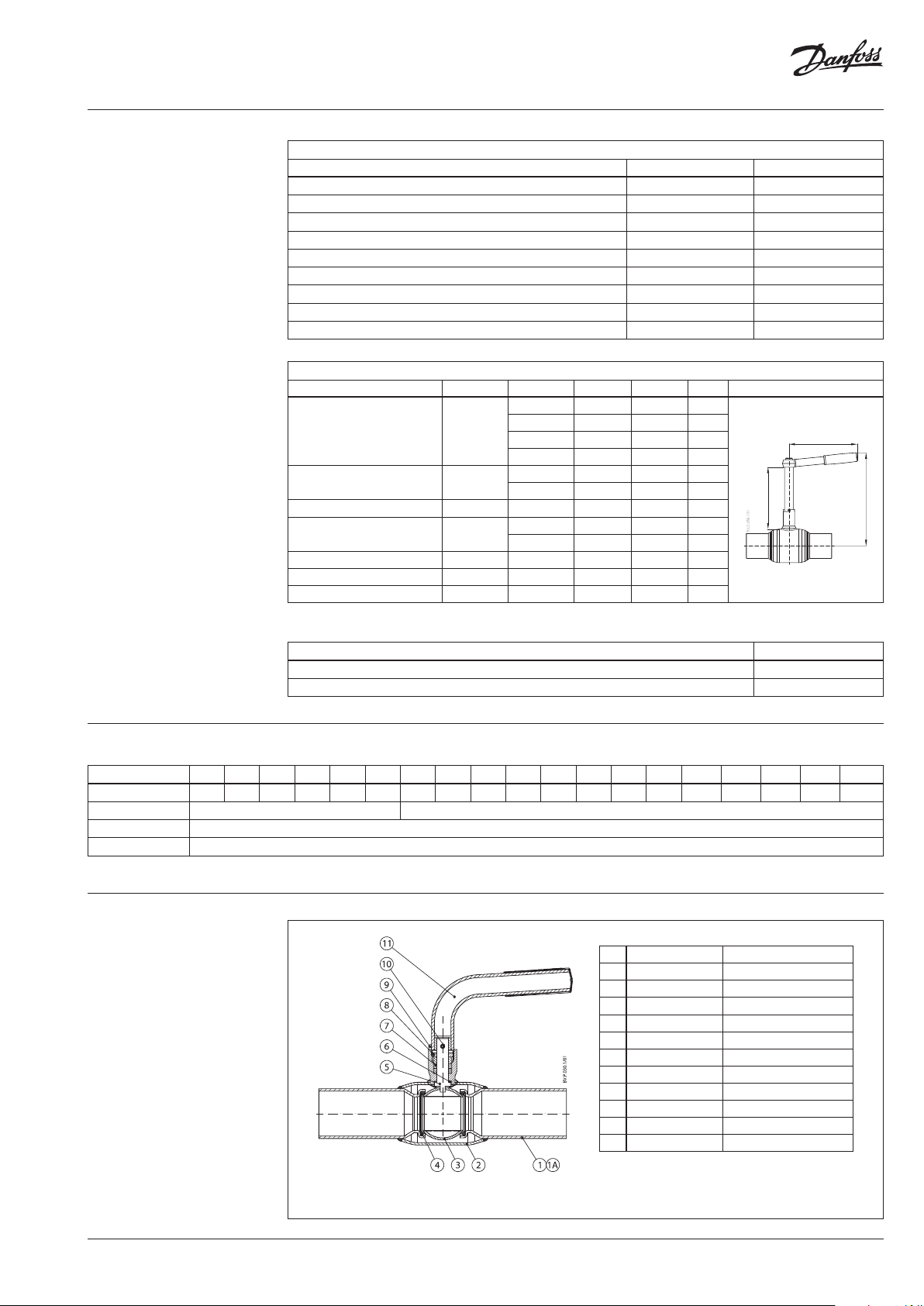
Design & Material
26,300
23,700 14,300
1 Welding end *Weldable mild steel 20#
1A Flange *Weldable mild steel 20#
2 Shell *Weldable mild steel 20#
3 Ball Stainless steel
4 Ball seal Carbon reinforced PTFE
5 Stem Stainless steel
6 Washer Carbon reinforced PTFE
7 Stem sealing rings Carbon reinforced PTFE
8 Compression nut Steel
9 Packing box *Weldable mild steel 20#
10 Pin Spring steel
11 Handle Steel
DN 15-50 with handle
AI144586457954en-011102 | 5© Danfoss | 2021.08
Page 6

Data sheet Standard JIP™ ball valves
Design & Material
1 Welding end *Weldable mild steel 20#
1A Flange *Weldable mild steel 20#
2 Shell *Weldable mild steel 20#
3 Ball seal retainer *Weldable mild steel 20#
4 Ball Stainless steel
5 Pipe insert Stainless steel
6 Support ring Stainless steel
7 Disc spring Domex 650 MC
8 Ball seal Carbon reinforced PTFE
9 Stem Stainless steel
10 Washer Carbon reinforced PTFE
11 Stem sealing rings Carbon reinforced PTFE
12 Compression ring Steel
13 Compression nut Steel
14 Packing box *Weldable mild steel 20#
15 Pin Spring steel
16 Handle Steel
DN 100-150 handle
DN 65-80 with handle
1 Welding end *Weldable mild steel 20#
1A Flange *Weldable mild steel 20#
2 Guiding pipe *Weldable mild steel 20#
3 Shell *Weldable mild steel 20#
4 Ball seal retainer *Weldable mild steel 20#
5 Ball Stainless steel
6 Pipe insert Stainless steel
7 Ball seal Carbon reinforced PTFE
8 Disc spring Domex 650 MC
9 Stem Stainless steel
10 Washer Carbon reinforced PTFE
11 Packing box *Weldable mild steel 20#
12 Steam sealing rings Carbon reinforced PTFE
13 Compression ring Steel
14 Compression nut Steel
15 Stopsector Stainless steel
16 Handle Steel
DN 200 with handle
6 | AI144586457954en-011102 © Danfoss | 2021.08
Page 7

Data sheet Standard JIP™ ball valves
Design & Material
1 Welding end *Weldable mild steel 20#
1A Flange *Weldable mild steel 20#
2 Guiding pipe *Weldable mild steel 20#
3 Shell *Weldable mild steel 20#
4 Ball seal retainer *Weldable mild steel 20#
5 Ball Stainless steel
6 Guide pipe Stainless steel
7 Ball seal Carbon reinforced PTFE
8 Disc spring Domex 650 MC
9 Stem Stainless steel
10 Washer Carbon reinforced PTFE
11 Packing box *Weldable mild steel 20#
12 Stem sealing rings Carbon reinforced PTFE
13 Compression ring Steel
14 Compression nut Steel
15 Simmerring Rubber
16 Key Steel
* Acco rding to the GB/T8163. Or eq uivalent mild stee l in accordance
with CE-PED
DN 65-600 with gear flange
Technical data
Pressure drop/velocity
ΔP (bar)
1,0000
0,5000
0,1000
0,0500
0,0100
0,0050
0,0010
0,0005
20
32
65
15
40
350
400
150
300
450
DN
25/600
200
50
80
250
500
100
125
0,0001
0,1 1
0,5 5
AI144586457954en-011102 | 7© Danfoss | 2021.08
10
JiP RB
m/sec
Page 8

Data sheet Standard JIP™ ball valves
m3/h
∆P (bar)
Technical data
Pressure drop/flow
1,0000
0,5000
0,1000
0,0500
DN20
0,0100
0,0050
0,0010
0,0005
DN15
DN25
DN32
DN40
DN50
DN65
DN80
DN100
DN125
DN150
DN200
DN250
DN350
DN300
DN400
DN600
DN450
DN500
Pressure/temperature
JIP-WW
0,0001
110 100 1000 10000
550 500 5000
DN 15 -50
DN 65-600
JiP RB
Legend:
Normal operating area
(water)
Steam area
8 | AI144586457954en-011102 © Danfoss | 2021.08
Page 9

Data sheet Standard JIP™ ball valves
Pressure/temperature
JIP-FF
PN 16, DN 65-600
PN 25, DN 65-600
Legend:
Normal operating area
(water)
Steam area
PN 40, DN 15-50
AI144586457954en-011102 | 9© Danfoss | 2021.08
Page 10

Data sheet Standard JIP™ ball valves
S
L
ØA
L
H
S
L
H
ØB
O
G1 G2
G3
L
Hh
ØA
Dimensions
JIP-WW welding/
welding
ØC
F
ØD
ØA
Hg
F
T
ØC
ØB
ØD
E
JIP-II internal thread
DN
ØA T ØB ØD L H Hh Hg E F ØC S O G1 G2 G3
(mm)
PN 40
15 34
20 42.4 26.9 15 230 125 58 25 115 1.0
25
48.3
32
60.3
40 76 .1 48.3 32 260 170 54 35 157 2.3
50 76.1 2.9 60.3 40 300 175 54 35 157 2.8
65 102 2.9 76.1 50 260 160 265 105 97 73 35 205 200 113 40 100 6
80 12 7 3.2 88.9 65 270 190 306 116 110 88 39 260 250 129 54 131 11
100 159 3.6 114 .3 80 290 232 321 122 145 108 39 405 250 129 54 131 16
125 19 4 4 139. 7 10 0 315 250 356 125 165 109 44 505 250 129 58 132 22
150 219 4.5 168.3 125 340 310 378 135 205 109 49 505 250 129 58 132 30.3
200 273 6.3 219.1 150 390 315 401 131 245 118 60 650 250 129 58 132 45
250 356 6.3 273.0 200 530
300 457 8 323.9 250 660 661 237 400 19 9 100 450 242 107 255 2 21
350 457 8 355.6 250 760 661 237 400 18 3 100 450 242 107 255 229
400 521 8.8 406.4 300 820 714 281 480 217 140 450 285 143 323 304
450 711 10 457 400 122 5 829 317 690 297 168 500 324 147 337 724
500 711 11 508 400 12 20 829 317 690 272 16 8 500 324 147 337 739
600 7 11 12. 5 610 400 150 0 829 317 695 221 168 500 324 147 337 832
Weights are based o n PN 40/25 versions. DN 250 - DN 600: D imensions and weights are PN 25 and i ncluding worm gear.
21.3 13 230 125
2.6
33.7 20 230 130 56 25 115 1.2
42.4 25 260 135 56 25 115 1. 5
-
-
PN 25
613 224 340 181 88
61 25 11 5
-
450 169 78 192 110
-
Weight
(kg)
1.0
F
ØD
DN
ØA R ØD L
(mm)
15 42.4 ½” 15 90 65 35 125 55 25 11 5 0.6
10 | AI144586457954en-011102 © Danfoss | 2021.08
20 42.4 ¾” 15 90 65 35 125 55 25 115 0.8
25 48.3 1” 20 100 70 35 13 0 55 25 115 0.9
32 60.3 1 ¼” 25 105
40 76 .1 1 ½” 32 130 170 80 35 157 2.2
50 88.9 2” 40 150 175 80 35 157 3. 3
ØC
R
H
ØD
ØA
H
lowF lowH highF high
135 55 25 115 1. 2
-
F
ØC
ØC S
R
Weight
(kg)
Page 11

Data sheet Standard JIP™ ball valves
Hh
DF
S
L
ØB
L
S
H
I
G1 G2
G3
Dimensions
JIP-FF flange/flange
I
F
F
ØC
ØC
Hg
ØA
ØD
DF
ØA
E
L
O
DN
ØA ØD*
(mm)
15 34 13
20 42.4 15 150 105 19 12 5 58 25 115 2.9
25
48.3
32 60.3 25 180 140 10 13 5 59 25 115 4.8
40 76 .1 32 200 150 35 170 86 35 157 6.5
50 76 .1 40 230 16 5 35 175 86 35 15 7 8.7
- PN 16 PN 25 -
65 102 50 270 185 18 290 18 5 18 16 0 265 13 0 100 73 35 205 200 113 40 10 0 12
80 127 65 280 200 33 310 200 33 190 306 117 11 0 88 39 260 250 129 54 131 18
100 159 80 300 220 56 350 235 48 225 321 125 135 108 39 405 250 129 54 131 26
125 194 10 0 325 250 54 400 270 44 215 356 14 4 165 109 44 505 250 129 58 13 2 32
150 219 12 5 350 285 51 480 300 43 235 378 155 205 109 49 505 250 129 58 132 45
200 273 150 400 340 66 600 360 56 315 401 149 245 126 60 650 250 129 58 13 2 74
250 356 200 650 405 115 730 425 10 5
300 457 250 750 460 131 850 485 119 6 61 254 400 199 100 450 242 107 255 262
350 457 250 850 520 101 980 555 84 6 61 254 400 183 100 450 242 107 255 289
400 521 300 110 0 580 130 110 0 620 110 714 285 480 220 14 0 450 285 14 3 323 400
450 7 11 400 1255 640 206 12 55 670 191 829 322 690 297 16 8 500 324 147 337 819
500 711 400 1250 715 169 12 50 730 161 829 322 690 272 168 500 324 147 337 866
Weights are based o n PN 40/25 versions. DN 250 - DN 600: D imensions and weights are PN 25 and i ncluding worm gear.
ØD* - internal n ominal diameter
L DF I L DF I
PN 16 PN 40
130 95 23 125
20 160 115 15 130 57 25 115 3.5
-
H Hh Hg E F ØC S O G1 G2 G3
58 25 115
-
613 228 340 181 88
-
-
-
450 169 78 192 165
ØD
Weight
(kg)
2.2
JIP-IW internal head/welding
F
ØD
L
DN
ØA ØB R ØD* L
(mm)
15 42.4 21.3 ½” 15 160 65 40 125 60 25 115 0.9
20 42.4 26.9 ¾” 15 16 0 65 37 125 60 25 115 0.9
25 48.3 33.7 1” 20 165 70 37 130 55 25 115 1.0
32 60.3 42.4 1 ¼” 25 185
40 76 .1 48.3 1 ½” 32 195 17 0 86 35 157 2.3
50 88.9 60.3 2” 40 225 175 86 35 15 7 3.3
ØD* - internal n ominal diameter
ØC
R
H
ØA
low TF low
F
ØB
ØD
H
-
H
high LF high
135 58 25 115 1.4
ØC S
AI144586457954en-011102 | 11© Danfoss | 2021.08
ØC
Weight
(kg)
R
H
ØA
Page 12

Data sheet Standard JIP™ ball valves
S
H
ØA
ØK
DN 65 - DN 350
DN 400 - DN 600
Dimensions
JIP-FW flange/welding
I
F
DF
ØB
ØC
ØD
L
DN
ØA ØB ØD*
(mm)
15 34 21.3 13
20 42.4 26.9 15 190 105 19 125 58 25 115 2.0
25 48.3 33.7 20 195 115 15 130 57 25 115 2.4
32 60.3 42.4 25 220 140 10 135 59 25 115 3.4
40 76 .1 48.3 32 230 150 35 170 86 35 157 4.3
50 88.9 60.3 40 265 165 35 175 86 35 157 5.9
- PN 16 PN 25 -
65 102 76.1 50 265 185 18 265 185 18 160 73 35 205 7
80 127 88.9 65 275 200 33 275 200 33 19 0 88 39 26 0 9
100 159 114 .3 80 295 220 56 295 235 48 225 108 39 405 15
125 19 4 139.7 10 0 320 250 54 320 270 44 250 109 44 505 23
150 219 168.3 125 345 285 51 345 300 43 285 10 9 49 505 35
200 273 219.1 150 395 340 66 395 360 56 315 126 60 650 65
Weights are based o n PN 40/25 versions. DN 250 - DN 600: D imensions and weights are PN 25 and i ncluding worm gear.
ØD* - internal n ominal diameter
L DF I L DF I
PN 16 PN 40
180 95 23 125 58 25 115 1.7
-
H F C S
Weight
(kg)
Valve top and gear flange
DN
(mm)
Gear
flange
65
F07
80 45
100 43 39
125
l Ød n p q r
mm
31 16 27 5 13
41
20
6 165
4
F10/F12 50 30 46 8 26150
200
250
300
350
400
450
60 50 48 14 44.5 5
F16
65 60 51 18 53. 2
75 75 60 20 60
F25
115 100 91 28 80500
6
600
Gear
flange
F7
F10 11 125 102 70
F12 13 150 125 85
No.
of bolt holes
4
Diameter of
bolt holes
9 88 70 55
ØD ØK ØR
mm
F16 21 210 165 130
F25
F30 21 350 298 230
8
17 300 254 200
ød
p
r
n
ØR
l
Open position
q
n
ØK
ØD
ØR
r
l
ØD
q
Reduced bore
12 | AI144586457954en-011102 © Danfoss | 2021.08
Page 13

Data sheet Standard JIP™ ball valves
Dimensions
House insertions
Single valve
JIP-CC copper
JIP-IC internal thread / copper
Max temp. 130°
ØA
H
H
ØA
House insertions
Twin valve - single pipe
JIP-IC internal thread/copper
Max temp. 130°
L
DN
ØA ØB L CC L IC H
(mm)
15 42.4 18 /21.3/18 245 168 125 0.93
20 42 .4 22 255 175 125/125/105 0.93
25 48.3 28 2 55 18 0 130 1.10
ØD* - internal n ominal diameter
ØB
PN 16
ØB
HA C
DN
(mm)
A C H
PN 16
15 10 0-145 115 -20 0 65 2.83
20 10 0-145 115 -2 00 65 2 .75
Weight
(kg)
L
Weight
(kg)
House insertions
Twin valves - single pipe
JIP-WW welding
JIP -II internal thread
JIP IW internal thread/welding
HA C
HA C
DN
(mm)
15 10 0-145 115 -20 0 65 2.2
20 10 0-145 115 -2 00 65 2.2
25 10 0-145 115 -2 00 70 2.3
32 115 -16 0 115 -20 0 115 3.5
HA C
A C H
PN 40
Weight
(kg)
AI144586457954en-011102 | 13© Danfoss | 2021.08
Page 14

Data sheet Standard JIP™ ball valves
ØA
Dimensions
House insertions
Twin valves - double pipe
JIP-II/JIP-IW internal thread
C
C
H
JIP-WE cc welding / external
thread with closing cap
DN
(mm)
C H
PN 40
15 58 55 2.2
20 58 55 2.3
25 58 60 2.3
Weight
(kg)
HFH
ØB
ØD
L2
Thread
Brass cap & chain
L
DN
ØA ØB ØD* F L L2 H
(mm)
PN 40
15 42.4 21.3 15 40 175 115 65 105 ⁄” 19 1.0
20 42.4 26.9 15 37 175 115 65 105 ⁄” 19 1.0
25 48.3 33.7 20 37 185 115 67 105 1” 19 1.5
32 60.3 42 .4 25 38 195 130 75
40 76 .1 48.3 32 55 210 130 10 0 1 ⁄” 27 3.7
50 88.9 60. 3 40 54 240 150 10 5 2” 27 4.4
ØD* - internal n ominal diameter
H
L-handle
-
Thread
Hex.
1 ⁄” 19 2.0
Weight
14 | AI144586457954en-011102 © Danfoss | 2021.08
(kg)
Page 15

Data sheet Standard JIP™ ball valves
AUMA NORM electrical
actuators for Danfoss ball valves
Danfoss ball valves Auma Actuators
DN
(mm)
65-80 SQ 05.2 16
100 SQ 07. 2 32
125 -150 -200 SQ 10.2 32
250 SA 07.6+GS 100.3+VZ 4.3 142
300 -350 SA 07.6+GS 125.3+VZ 4.3 142
400 SA 10.2+GS 125.3+VZ 4.3 142
450-500-600 SA 10.2+GS 160.3+GZ 160.3 207
The actuators can be equipped with various
accessories.
Control and regulating unit AUMA Matic in the
basis design can be supplied.
For other mains voltages than 3 × 400V/50Hz or
additional questions please contact us.
When commissioning and under certain
problematic system conditions, it can be
necessary to choose slower actuators to avoid
water hammering and oscillations.
For additional information related to the electric
actuator ordering, please contact local Danfoss
representative.
Typ e
Operating time for 90º turn
Features:
• 2 limit switches - opening/closing
• 2 torque switches - opening/closing
• Heater
• Blinker switch for operating phase
• Manual operation with hand wheel
• Thermo switch
Main Data:
• Nominal voltage: 3 × 400 VAC, 50Hz
• Grade of enclosure: IP 68
• Wiring diagram: TPA 00R1AA-000
(s)
AI144586457954en-011102 | 15© Danfoss | 2021.08
Page 16

Data sheet Standard JIP™ ball valves
© Danfoss | DCS-S/SI | 2021.0816 | AI144586457954en-011102
 Loading...