

Danfoss
17916.10
Danfoss
17-914.10
Installation guide
min. 20mm
Danf
17917.10
Pressure switch
Type RT 112W
017R9313
1
017A1831-01
5
0.05
3
0.5
10
2
Danfoss
1.0
2
4
1
4
AC 1 10A DC 13
1
µ
AC 3 4A 12W
2
4030
AC 15 3A 220 V
250 V
Code no.
017xxxx
Fig. 1 Fig. 2
ENGLISH
Technical data
Fail safe pressure switch type R T 112 W
The meaning of the type designation letter is
as follow:
W: Pressure monitoring with automatic reset
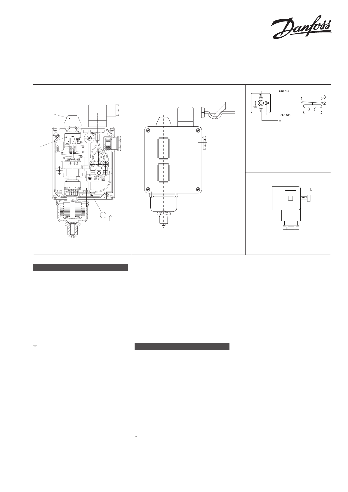
Contact load: see g.3
1. Inpu t
2. Normally closed (NC)
3. Normally open (NO)
Connected to chassis of pressure switch
Max. ambient temperature: -40 °C – 70 °C
Max. temperature of medium: 150 °C
Max. test pressure: 7 bar
Min. test pressure: - 1 bar
Enclosure: IP65 acc. to EN 60529
Installation
Make the pressure connection so that any
impurities in the line do not block the pressure
inlet of the control.
For example, t the pressure control to an
upright connector (with the unit vertical).
Damp strong pressure pulsations. A damping
loop will often be sucient. Insert a water-lled
loop as a temperature barrier; a 10mm Cu tube,
for example, if in a high temperature plant
there is a risk of the pressure connection to the
control becoming heated to more than 100 °C.
e
oss
In water plant, position the pressure control so
that it cannot be exposed to frost (let it operate
on an air cushion, for example).
To ensure IP65 grade of RT enclosure it is
necessary to assemble the plug shown in the
g. 4
Setting
The pressure switch must be set to provide the
function - make or break - on rising pressure.
The setting can be made with
the setting knob (1) while at the same time
reading o the main scale (2). See g. 1.
DEUTSCH
Technische Daten
Selbstüberwachende Pressostate
Typ RT 112W
Die Buchstaben der Typenbezeichnung
haben folgende Bedeutung:
W: Druckwächter mit automatischer
Wiedereinschaltung.
Kontaktbelastung: Siehe Fig. 3
1. Eintritt
2. Stromlos geschlossen (NC)
3. Stromlos geönet (NO)
Verbunden mitdem Druckreglergehäuse
Max.Umgebungstemperatur: -40 °C – 70 °C
Max. Mediumtemperatur: 150 °C
AC-1: 10A, 250V
AC-3: 4A, 250V
AC-15: 3A, 250V
DC-13: 12W, 220V
Fig. 3
0.4 0.1 Nm
93Z265.10
Fig. 4
Max.Prüfdruck: 7 bar
Min. Prüfdruck: - 1 bar
Schutzklasse: IP65 nach EN 60529
Montage
Der Druckanschluss ist so auszuführen, dass
eventuelle Unreinheiten in der Leitung nicht
den Druckeingang des Pressostats verstopfen.
Der Pressostat ist z.B. an einen nach
oben gerichteten Stutzen anzuschliessen
(Gerät senkrecht).
Kräftige Druckpulsationen dämpfen. Oftmals
ist eine Dämpfschleife ausreichend. Wenn bei
Anlagen mit hohen Temperaturen die Gefahr
besteht, das sich der Druckanschluss des
Pressostats auf über 100 °C erwärmen kann, ist
eine mit Wasser gefüllte Rohrschleife, z.B. aus 10
mm Cu-Rohr, als Temperatursperre einzubauen.
Den Pressostat ist so anzubringen, dass er
an Wasseranlagen nicht Frost ausgesetz ist.
(Den Pressostat eventuell auf einem Luftkissen
arbeiten lassen).
Um den Schutzgrad von IP65 für das RT
Gehäuse zu gewährleisten, muss der Stecker
Fig.4 montiert werden.
Einstellung
Der Pressostat ist nach die Funktion
- Einschalten oder Ausschalten - einzustellen,
-die für steigende Druck ausgeführt werden
soll.
Die Einstellung ist mit dem Einstellknopf
(1) vorzunehmen und gleichzeitig an der
Hauptskala (2) abzulesen.
Siehe Fig. 1.
e
017R9313
© Danfoss | DCS / (jmn) | 2015.07 IC.PI.P10.K1.02 / 520B6413 1
 Loading...