

Page 1
1035016, 1037034
PHASED OUT PRODUCT
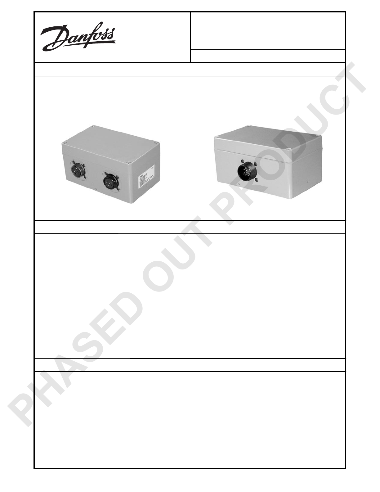
Proler RS-485/CAN Gateway
BLN-95-9079 Issued: September 2003
DESCRIPTION
The Proler RS-485/CAN Gateway acts as a bridge between TSD/TOPCON RS-485 bus System 5 controls and sensors and CAN
based controllers and displays, which can be TSD/Danfoss controllers and displays or third party controllers and displays.
In this application, the gateway acts as a bus master sending setpoint data commanded from the CAN bus controller and display
to the System 5 machine controls.
FEATURES
• Full capability CAN bus
• RS-485 bus
• RS-232 programming port/WebGPI™ application port
• 12 to 24 V operation
• Designed to withstand the mobile environment
• -40 to 70° C operating range
• 95% relative humidity
• Meets off-highway vibration standards
• Protected against static discharge, EMI, and RFI
ORDERING INFORMATION
• 1035016 125kBaud version
• 1037034 250kBaud version
© Danfoss, 2013-09 BLN-95-9079 1
Page 2
TECHNICAL DATA
PHASED OUT PRODUCT
Supply Voltage
• 12 to 24 V
CAN Interface
• CAN 2.0b bus
• Both applications use 11-bit identiers
• 1035016 is at 125kBaud; 1037034 is at 250kBaud
RS-485 Bus
• RS-485 bus with proprietary Topcon protocol (the bus is terminated on the circuit board)
RS-232 Interface
This interface is used in conjunction with WebGPI™, which can be used for downloading code, monitoring the application,
and logging data.
Digital Input
A digital input, Select, pulled high internally, can be used by the application as a general digital input or to allow up to two
differentiate gateways to coexist on the same CAN bus. Shorting this pin to ground will change the digital state..
Operating Temperature
• -40 to +70° C
Mating Connectors
• 10-pin, CS3106A18-1S(472)
• 8-pin, MS3116E16-6P
Gateway Current
• 300 mA
Mounting
Must be mounted vertically so a drain hole is always facing the ground.
ENVIRONMENTAL
EMI/RFI
The sensor will meet performance specications while subject to the following electromagnetic radio frequency interference:
• 20 V per meter between 14 KHz and 1 GHz
• 60 V per meter over 147 to 162 MHz
• 100 V per meter over the ranges:
• 24 to 51 MHz
• 163 to 175 MHz
• 445 to 517 MHz
• 798 to 875 MHz
All EMI/RFI specications subject to shielded cabling.
Temperature Rating
• -40 to 70° C (-40 to 158° F) operating
• -55 to 125° C (-67 to 257° F) storage
Vibration
Withstands a vibration test designed for mobile equipment controls that consists of two parts:
1. Cycling from 5 to 2000 Hz for a period of one hour (if there are four resonant points) to three hours (if there is one or no
resonant point) at 5.58 g RMS. Cycling test performed on each of the three major axes.
2. Rsonant dwell for one million cycles for each of the four most severe resonant points on each of the three major axes.
Shock
• 50 g for 11 milliseconds (three shocks in both directions of the three mutually perpendicular axes for a total of 18 shocks)
Humidity
After being placed in a controlled atmosphere of 95 % humidity at 38° C (100° F) for 10 days, the sensor will perform within
specication limits.
BLN-95-9079 September 2013
2
Page 3

DIMENSIONS
PHASED OUT PRODUCT
Dimensions of the 1035016, 1037034 Proler RS-485/CAN Gateway in millimeters [inches]
100 [3.93]
View without cover
66 [2.60]
7 [.276]
9 [.35]
Bottom mounting surface
4.8 [.189]
CONNECTORS
Shell 16 arrangement connector
A
B
C
H
D E
146 [5.74]
160 [6.29]
G
F
Cover mounting screw
20 [.79]
81 [3.19]
61 [2.40]
Assembled height
2189
2193
18-1 arrangement connector
H
G
F
BLN-95-9079 September 2013
A
B
I
C
J
E
D
2194
3
Page 4

WIRING DIAGRAM
CUSTOMER SERVICE
TSD Integrated Controls
A TOPCON/Sauer-Danfoss Joint Venture Company
Website: www.tsdcontrols.com
3500 Annapolis Ln. N.
Minneapolis, MN 55447
5758 W. Las Positas Blvd.
Pleasanton, CA 94688
Phone: 925-468-3256
PHASED OUT PRODUCT
8-Pin Connectors
Comm_A
Comm_B
Right Side Connector
(Looking at the 2 connector side)
N/C
* These 5 connections are
internal to the gateway
A
B
C
D
E
F
G
H
10-Pin Connector
RS-232 Tx
A
B
C
D
E
RS-232 Rcv
Select
CAN_Hi
CAN_Low
Ground
F
*
*
*
*
*
G
H
I
J
Battery +
/Boot
Ground
CAN_Shield
Left Side Connector
A
B
C
Comm_A
D
E
Comm_B
N/C
F
G
H
A TOPCON/Danfoss Joint Venture Company
2191
BLN-95-9079 September 2013
4
 Loading...