

Instructions
RMT-24, RMT-24T, RMT-24R
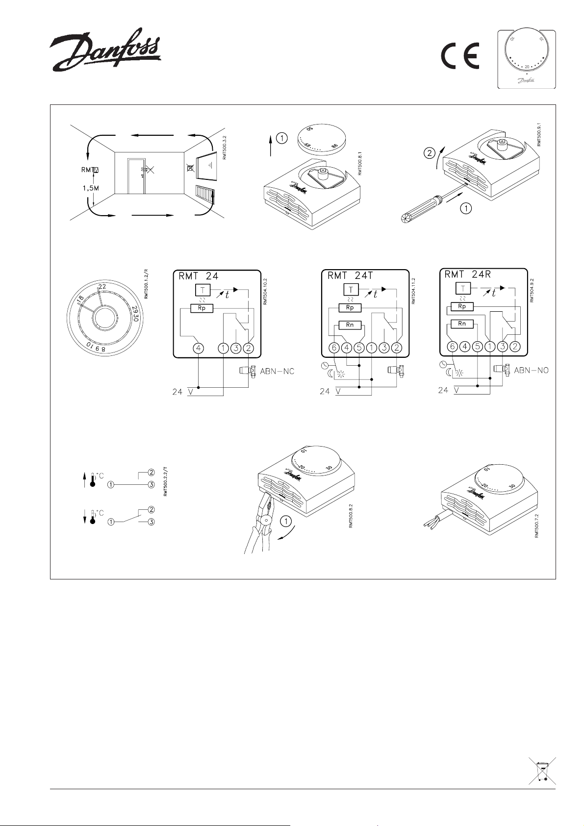
Fig. 1.
Fig. 4.
Fig. 5.
Fig. 2.
Fig. 6.
Fig. 3.
Fig. 7.
Fig. 8.
Location, fig. 1.
Do not site the room thermostat in a
draught, in direct sunlight or close to
appliances giving off heat (e.g. television
set).
Fixing, fig. 2. and 3.
Make sure the supply voltage to the system
is disconnected before commencing
installation or subsequentially removing
the thermostat cover.
Fix the base moulding on a flat wall or on
a flush box.
The temperature range can be limited by
moving the two springs on the back of the
setting knob, fig. 4.
Fig. 9.
Wiring, fig. 5, 6 & 7.
Switch function: SPDT, fig. 8, 24V, 5060Hz, 10 (4) A.
Min. contact load: 70 mA
When the cable is to be wired through the
side of the thermostat, break out the
knockout with a pair of pliers (fig. 9 & 10).
When the room thermostat is connected
to an inductive load, without noise
suppression, there might be a risk of radio
and TV interference.
RMT versions with parallel accelerator
Rp, will have a lower temperature
differential when terminal is connected
as shown in fig. 5 & 6.
Fig. 10.
RMT-24T and RMT-24R only
RMT-24T and RMT-24R will set-back the
temperature by 5K, when the built-in
resistance Rn is connected as shown in
fig. 6 & 7.
NB. RMT-24R is only to be applied together
with an ABN actuator of the NO-type
(Normally Open).
Part No: 9106 Iss.2. 05/05
 Loading...