

Page 1
Instructions
T
ss
Rp
4 1 3 2
t
N
L
T
1 3 2
t
N
L
T
ss
Rp
4 1 3 2
t
N
L
6
5
Rn
RMT-230, RMT-230T
087R9127
Fig. 1 Fig. 2 Fig. 3
RMT230T
Fig. 4
RMT230
RMT230
087R9127
Fig. 8
ENGLISH
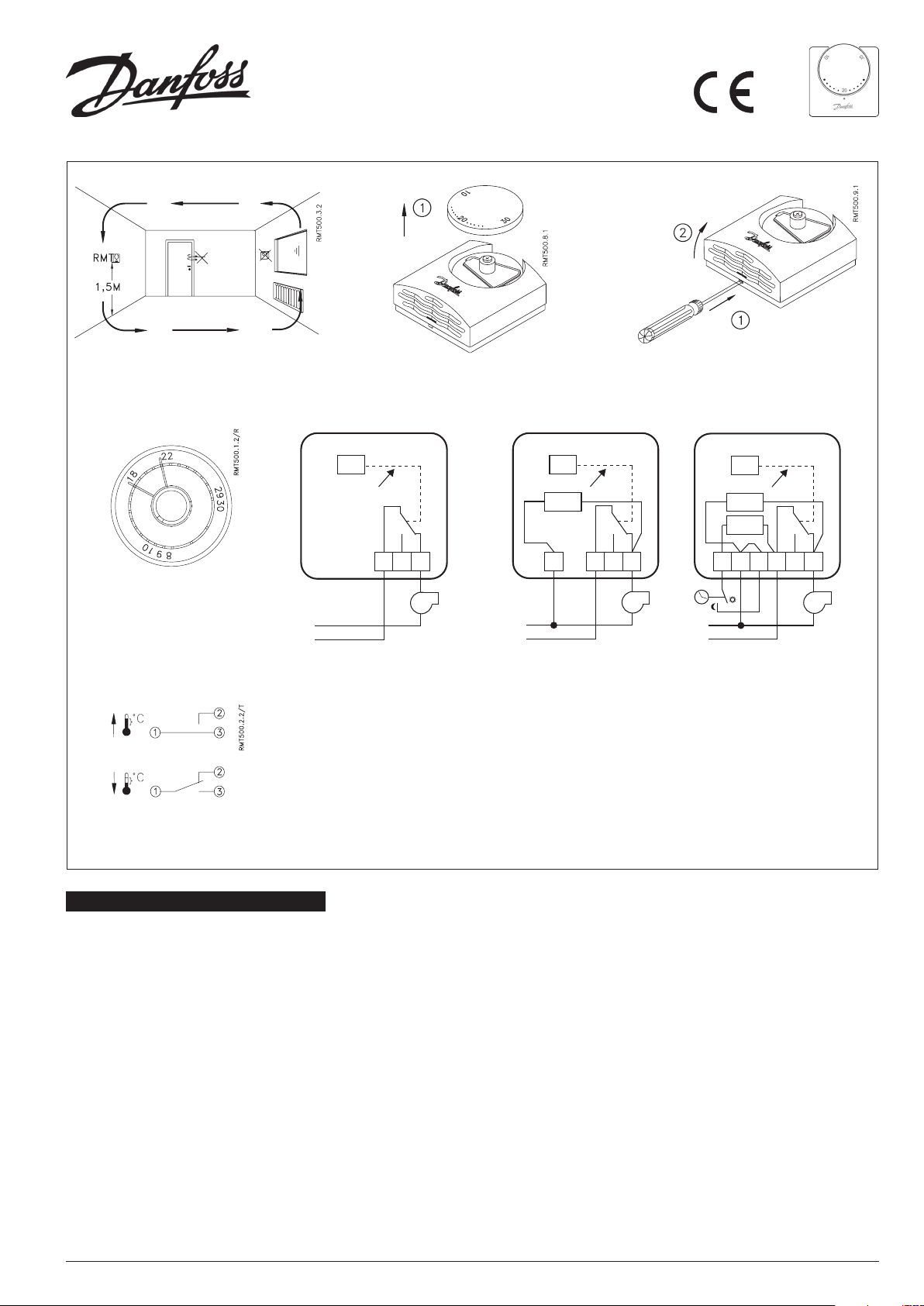
Location, Fig. 1
Do not site the room thermostat in a draught, in
direct sunlight or close to appliances giving off
heat (e.g. television set.)
Fixing, Fig 2 and 3
Make sure the supply voltage to the system is
disconnected before commencing installation
or subsequentially removing the thermostat
cov er.
Fix the base moulding on a flush box. The
temperature range can be limited by moving
the two springs on the back of the setting dial,
Fig 4.
Wiring, Fig 5, 6 and 7
Switch function: SPDT, Fig 8
230 V, 50 - 60 Hz, 10 (4) A
Min. contact load: 150 mA
Note: Always connect the live (L) to terminal .
Fig. 5 Fig. 6 Fig. 7
When the room thermostat is connected to an
inductive load, without noise suppression, there
might be risk of radio and TV interference.
RMT versions with parallel accelerator Rp, will
have a lower temperature differential when
terminal is connected as shown in Fig. 6 and
7.
RMT-230T only
RMT-230T will set back the temperature by 5K,
when the built-in resistance Rn is connected as
shown in Fig. 7.
Note:
A means of disconnecting the supply with a
contact separation of at least 3mm in all poles
must be incorporated in the fixed wiring,
according to BS 3955. This product does not
require an earth connection.
Page 2
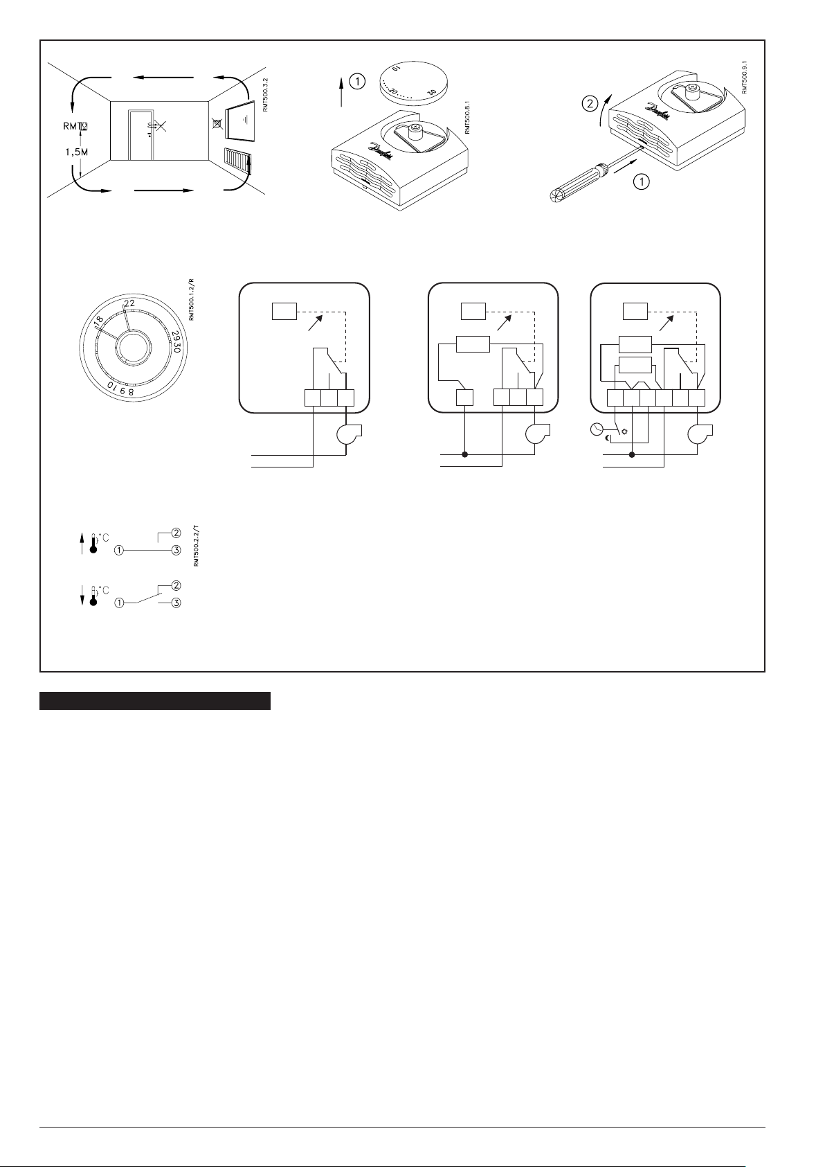
Fig. 1 Fig. 2 Fig. 3
T
ss
Rp
4 1 3 2
t
N
L
T
1 3 2
t
N
L
T
ss
Rp
4 1 3 2
t
N
L
6
5
Rn
Fig. 4
Fig. 8
RMT230
Fig. 5 Fig. 6 Fig. 7
RMT230
RMT230T
FRANCAIS
Choix de l’emplacement, Fig. 1
Le thermostat RMT détecte une température
ambiante considérée comme représentative. Il
doit donc être placé dans la pièce la plus froide,
à l’abri des courants d’air et des sources de
chaleur telles que soleil, poste de télévision ou
autres.
Montage, Fig 2 et 3
Couper l’alimentation avant de retirer le
couvercle.
Fixer le socle du thermostat sur une boîte
encastrée en évitant les parois trop froides. La
plage de réglage peut être limitée par 2 butées
situées au revers du bouton de réglage de
température, Fig 4.
Raccordements, Fig 5, 6 et 7
Pouvoir de coupure: 230 V, 50 - 60 Hz, 10 (4) A
Charge mini de contact: 150 mA
Contact inverseur unipolaire SPDT: voir fig. 8
Attention: Toujours raccorder la phase sur la
borne .
Lorsque le RMT commande un relais ou une
charge inductive, il est probable que certains
parasites radio ou TV se produisent.
Le thermostat RMT avec résistance anticipatrice
a un faible différentiel de température pour
assurer une régulation plus fine. Raccorder dans
ce cas le borne comme indiqué Fig. 6 et 7.
RMT-230T
Il est possible de réasliser un abaissement de
température de 5 K avec le modèle RMT-230T.
Raccorder dans ce cas la résistance incorporée
Rn comme indiqué sur la Fig. 7.
Page 3

DANSK
Placering, Fig. 1
Placer ikke rumtermostaten i træk, i direkte sol
eller i nærheden af apparater der afgiver varme
(fx. TV).
ESPAOL
Instalación, Fig. 1
No instalar el termostato en una corriente de
aire, en un punto soleado o cerca de una fuente
de calor (ej. televisor).
Montering, Fig 2 og 3
Afbryd spændingsforsyningen inden dækslet
ernes.
Monter bundparten på en indmuringsdåse.
Temperaturområdet kan begrænses ved at flytte
de to edre på bagsiden af indstillingsknappen,
Fig 4.
Elektrisk tilslutning, Fig 5, 6 og 7
Kontaktfunktion: SPDT, fig. 8
230 V, 50 - 60 Hz, 10 (4) A
Min. kontaktbelastning: 150 mA
Bemærk: Tilslut altid fasen til klemme .
Hvis rumtermostaten tilsluttes en kontaktor
eller anden induktiv belastning der ikke er
støjdæmpet, er der risiko for radio/TV-støj.
På de RMT-udgaver som er forsynet med en
parallelaccelerator Rp, opnås der en lavere
temperaturdifferens, når klemme forbindes
som vist på fig. 6 og 7.
Kun RMT-230T
Ved at tilslutte den indbyggede modstand Rn
som vist på fFig. 7, opnås en natsænkning på
5K.
Montaje, Fig. 2 y 3
Desconectar la tensión de alimentación antes
de quitar la tapa.
Montar la parte posterior sobre una caja a ras.
La gama de temperatura puede ser limitada
moviéndo los dos muelles de la parte posterior
del botón de ajuste, fig 4.
Conexión eléctrica, Fig 5, 6 y 7
Función de contacto: SPDT, fig. 8
230 V, 50 - 60 Hz, 10 (4) A
Minima carga del contacto: 150 mA
Nota: Conectar siempre la fase al terminal .
Cuando se conecta un termostato de ambiente
a un contacto u otra carga inductiva, sin
supresión de ruido, pueden surgir interferencias
de radio o TV.
Versiones RMT con acelerador paralelo Rp,
tendrán un diferencial de temperatura menor
cuando el terminal se conecta como se
observa en fig. 6 y 7.
RMT-230T, solamente
El RMT-230T reducirá la temperatura 5K, cuando
la resistencia incorporada Rn se conecta según
la fig. 7.
DEUTSCH
Plazierung, Abb. 1
Der Raumthermostat soll nicht im Zug, direkt
in der Sonne oder nah an Geräten, die Wärme
abgeben (z.B. Fernsehgeräten) plaziert werden.
Montage, Abb 2 und 3
Die Versorgungsspannung soll unterbrochen
werden, bevor der Deckel entfernt wird.
Bodenplatte auf einer Unterputzdose
montieren.
Der Temperaturbereich kann begrenzt werden,
wenn die zwei Federn hinter dem Einstellknopf
verschoben werden, Abb. 4.
Elektrischer Anschluss, Abb. 5, 6 und 7
Schalterfunktion: SPDT, Abb. 8
230 V, 50 - 60 Hz, 10 (4) A
Min. Kontaktbelastung: 150 mA
Beachte: Die Phase immer an Klemme
anschliessen.
Wenn der Raumthermostat einem Schalter
oder einer ähnlichen induktiven Belastung
ohne Störschutz angeschlossen ist, können
Störungen vorkommen.
Durch Anschluss der thermischen Rückführung
Rp, wird die Schaltdifferenz reduziert
Schaltdifferenz ohne Rp: ca. o,6 K
Schaltdifferenz mit Rp: ca. 0,3 K
Der Anschluss erfolgt über Klemme wie in
Abb. 6 und 7 dargestellt.
Nur RMT-230T
Bei RMT-230T wird die Temperatur um 5K
reduziert, wenn der eingebaute Widerstand Rn
angeschlossen wird, siehe Abb. 7.
ITALIANO
Posizionamento, Fig. 1
Accertarsi che il termostato ambiente non
venga interessato da spifferi, irraggiamento
solare o calore proveniente da altre fonti (es.
televisione).
Installazione, Fig. 2 e 3
Togliere corrente prima di rimuovere il
coperchio.
Montara la piastra di fondo su una scatola di
derivazione ad incasso. Il campo di temperatura
può essere limitato muovendo le due molle sul
retro della manopola di regolazione, Fig. 4.
Collegamenti elettrici, Fig. 5, 6 e 7
Tipo contatto: SPDT, Fig. 8
230 V, 50 - 60 Hz, 10 (4) A
Minimo carico: 150 mA
NB: La fase va sempre collegata al terminale .
Quando il termostato ambiente è collegato ad
un altro interruttore o ad un carico induttivo,
senza soppressore di disturbi, ci può essere il
rischio di interferenze radio o TV.
Collegando l’acceleratore in parallelo Rp
del terminale come in fig. 6 e 7, si riduce il
differenziale termico del termostato RMT.
Esclusivamente per RMT-230T
Collegando come in Ffig. 7, la resistenza
notturna Rn il valore impostato viene ridotta di
5K.
Page 4

SVENSKA
Placering, Fig. 1
Placera inte rumstermostaten i drag, direkt sol
eller i närheten av apparater som avger värme.
Montering, Fig. 2 och 3
Bryt strömmen innan kåpan demonteras.
Montera bottenplattan på en inmumingsdosa.
Temperaturområdet kan begränsas genom
att flytta de två ädrama på baksidan av
inställningsknappen, Fig. 4.
Elektrisk anslutning, Fig. 5, 6 och 7
Kontaktfunktion: SPDT, Fig. 8
230 V, 50 - 60 Hz, 10 (4) A
Min. kontaktbelastning: 150 mA
Observara: Anslut alltid fasen till plint .
Om rumtermostaten ansluts till en kontaktor
eller annan induktiv belastning som inte är
störningsskyddad, år det risk för radio/TVstörningar.
På de RMT-termostater som är försedda med
en parallell-accelarator Rp, erhälls en lägre
temperatur-differens, nar plint ansluts enligt
fig 6 och 7.
Endast RMT-230T
Genom att ansluta det inbyggda motståndet Rn
enligt fig 7, erhålls en nattsänkning på 5 grader.
NEDERLANDS
Plaastsing, afb. 1
Plaats de thermostaat op ooghoogte, bij
voorkeur op een binnemuur, waar de RMT
niet direct wordt beïnvloed door koude
luchtstromen, opstijgende warmte van
radiatoren, schemerlampen, TV en zonlicht.
Montage, afb. 2 en 3
Onderbreek de voedingspanning alvorens het
deksel te verwijderen.
Monteer de bodemplaat op een inbouwbus.
Het temperatuurbereik kan worden begrensd
door de twee veren achter de instelknop te
verschruiven, afb. 4.
Elektrische aansluiting, afb. 5, 6 en 7
Schakelfunctie: SPDT, afb. 8
230 V, 50 - 60 Hz, 10 (4) A
Min. contactbelasting: 150 mA
Opmerking 1: De fase steeds aansluiten aan
klem .
Opmerking 2: De RMT 230 zonder
acceleratieweerstand wordt in Nederland niet
op de markt gebracht.
Wanneer de kamerthermostaat een relais
of een andere inductieve belasting - zonder
ontstoringsfilter - bedient, kunnen zich
storingen op TV en radio voordoen.
De RMT dient steeds drie-draads te worden
aangesloten. Thermische schakeldifferentie: 0,3
- 1 K (°C) afhankelijk van soort installatie.
Alleen RMT-230T
(met nachtverlagingsweerstand)
Bij RMT-230T wordt de temperatuur met 5K
verlaagd, wanneer de ingebouwde weerstand
Rn op 220 V wordt aangesloten, zie afb. 7.
SUOMEKSI
Sijoituspaikka, kuva 1
Älä sijoita huonetermostaattia vetoiseen
kohtaan, suoran auringonpaisteen kohteeksi tai
lämpöä luovuttavien esineiden, esim. television
läheisyyteen.
Kiinnitys,kuvat 2 ja 3
Varmistaudu ennen laitteen asennukseen
ryhtymistä tai termostaatin kannen avaamista,
että järjestelmän verkkojännite on katkaistuna.
Kiinnitä asennuspohja tasaiselle seinäpinnalle
tai upotetun jakorasian pintaan.
Lämpötila-aluetta voidaan rajoittaa siirtämällä
säätönupin takana olevia jousia, kuva 4.
Johdotus, kuvat 5, 6 ja 7
Kytkentätoiminto: SPDT, kuva 8
230 V, 50 Hz ... 60 Hz, 10 (4) A
Minimi kosketinkuorma: 150 mA
Huomaa: Kytke vaihe aina liittimeen .
Jos huonetermostaatti liitetään katkaisimeen
tai muuhun induktiiviseen kuormaan, jossa ei
ole häiriösuojausta, radiossa tai TV:ssä saattaa
ilmetä häiriöitä.
RMT-tyypeissä, joissa on rinnan kyteketty
kiihdytysvastus Rp, saadaan pienempi
lämpötilaero, kun kosketin kytketään kuvien
6 ja 7 mukaisesti.
Koskee vain RMT-230T
RMT-230T alentaa lämpötilaa 5K, kun vatus Rn
kytketään kuvan 7 mukaisesti.
VIRLC102
 Loading...