

Data Sheet
Valve Body Type RA-FN/HC, Lock Shield Valve
Type RLV-S/HC
Application
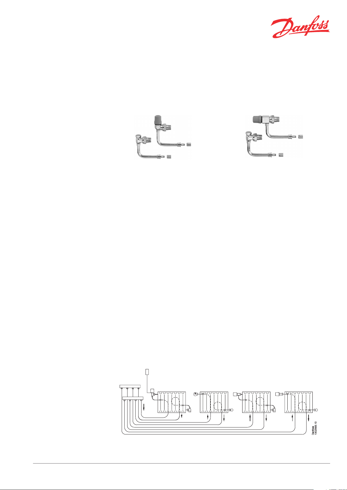
RA-FN/HC Angle RA-FN/HC Reversed angle (UK)
RA-FN/HC:
All RA-FN/HC valve bodies can be used together
with all types of thermostatic elements with RA
connection. The valve body RA-FN/HC is used in
two-pipe heating systems.
The valve bodies are supplied with a protective
cap which can be used for manual regulation
during the construction phase.
The protective cap must not be used as a manual
shut off device. A special manual shut off device
(code no. 013G5002) should be used.
To be able to distinguish between other valve
bodies of the RA 2000 series the RA-FN/HC protective cap is grey.
RA-FN/HC has connection for 12 mm hydro cable
both axial and radial compression fittings are
available. RA-FN/HC are also available with 1/2”
conection.
Valve bodies are manufactured from brass with
nickel plating. The pressure pin of the gland seal
is of chrominium steel and works in a lifetime lubricated O-ring. The complete gland assembly(stuffing box) can be replaced without draining down the system.
Should water treatment be used it is essential
that dosing instructions of the manufacturer are
strictly observed. It is recommended that formulations containing mineral oil are avoided.
RLV-S/HC:
By means of a lockshield valve, type RLV-S/HC,
every radiator can be shut off individually to allow trouble-free maintenance or repair without
affecting other radiators in the system.
RLV-S/HC is intended for mounting on the outlet
of the radiator.
RLV-S/HC lockshield valves are available in angle
version. RLV-S/HC has connection for 12 mm hydro cable both axial and radial compression fittings are available. RLV-S/HC are also available
with 1/2” conection.
kvs-value RLV-S/HC 15 = 1.26 m³/h
Factory setting is fully open valve.
Dimensions correspond to DIN 3842-1.
In order to avoid deposition and corrosion the
composition of the hot water must be in accordance with the VDI 2035 guideline (Verein
Deutscher Ingenieure).
Principles
Danfoss Heating Solutions VDSXD302 © Danfoss 02/2013 1
Data Sheet Valve Body Type RA-FN/HC, Lock Shield Valve Type RLV-S/HC
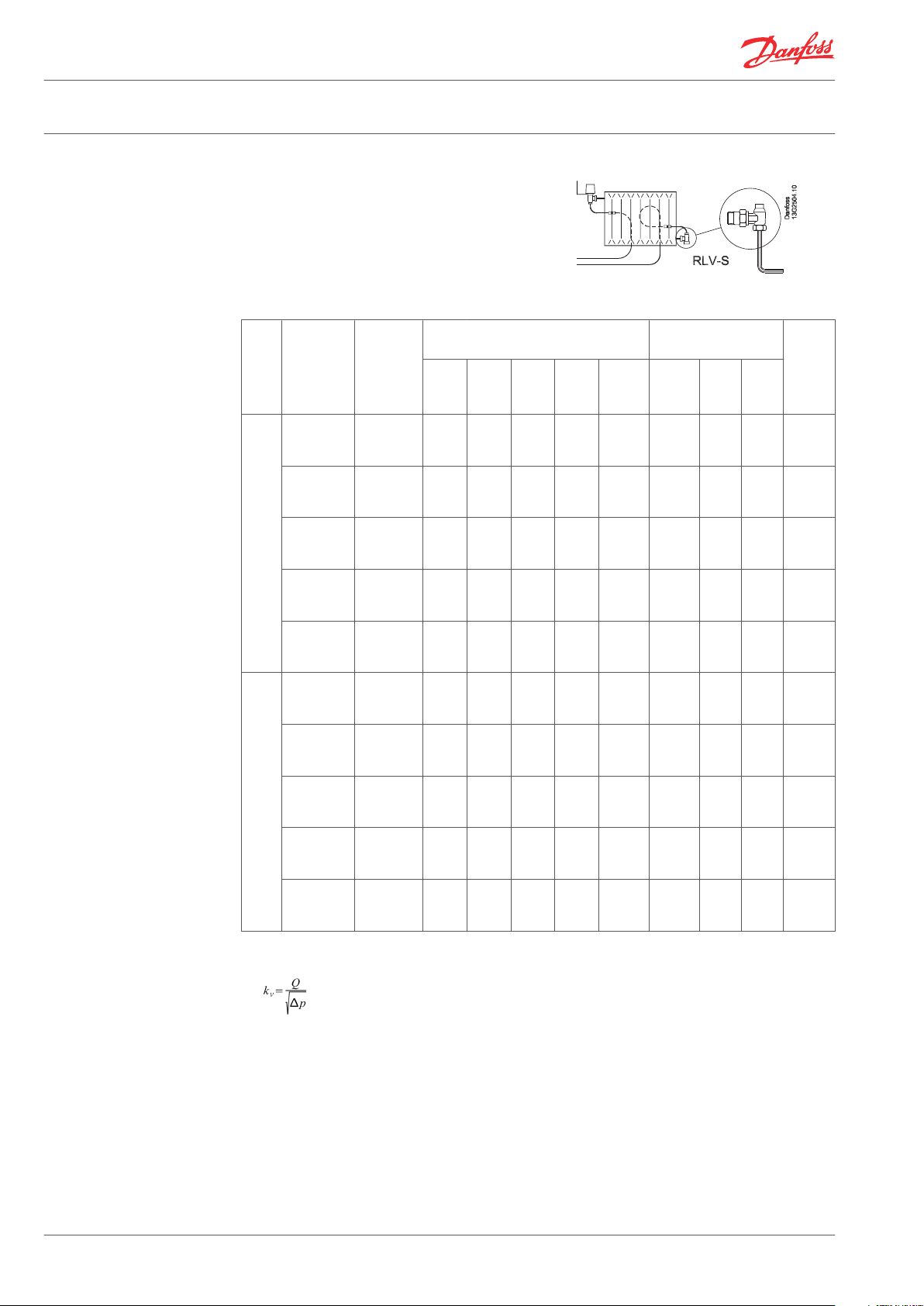
Closing/Opening RLV-S
Data and Ordering
Close the valve by means of an 8 mm allen key
(turn allen key right).
Open RLV-S with 4 turns and the valve will be
fully open (turn allen key left).
kv-value (RA-FN/HC)1) (m³/h at 1 bar
Pattern
Type RA-
FN 15/
RLV-S 15
Code No.
pressure drop) P-band = K
0.5K 1.0K 1.5K
C/C 33/45,
Axial press
013G3190 0.13 0.26 0.38 0.49 0.94 10 0.6 16 90
fit
C/C 33/45,
Radial
013G3191 0.13 0.26 0.38 0.49 0.94 10 0.6 16 90
press fit
C/C 75,
An-
gle
Axial press
fit
013G3192 0.13 0.26 0.38 0.49 0.94 10 0.6 16 90
C/C 75, Ra-
dial press
013G3189 0.13 0.26 0.38 0.49 0.94 10 0.6 16 90
fit
C/C 75,
1/2”
013G3200 0.13 0.26 0.38 0.49 0.94 10 0.6 16 90
thread
C/C 50/45,
Axial press
013G3195 0.14 0.27 0.39 0.49 0.71 10 0.6 16 90
fit
C/C 50/45,
Radial
013G3196 0.14 0.27 0.39 0.49 0.71 10 0.6 16 90
press fit
C/C 75,
UK
Axial press
013G3197 0.14 0.27 0.39 0.49 0.71 10 0.6 16 90
fit
C/C 75, Ra-
dial press
013G3198 0.14 0.27 0.39 0.49 0.71 10 0.6 16 90
fit
C/C 75,
1/2”
013G3199 0.14 0.27 0.39 0.49 0.71 10 0.6 16 90
thread
Kv,
2.0K
K
vs
Fully
open
Test
Max.
Work-
ing
temp.
°C
Max. pressure
3)
Work-
ing
(bar)
Diff.
2)
(bar)
(bar)
1)
The kv-value indicates the water flow (Q) in m³/h at a pressure drop (∆p) across the valve of 1 bar;
. The kv-value is stated according to EN 215, at XP = 2K i.e. the valve is closed at 2°C higher room
temperature. At lower settings the XP value is reduced to 0.5K. The kvs-value states the flow Q at a maximum lift, i.e. at fully open valve.
2)
Working pressure = static + differential pressure. The maximum differential pressure specified is the
maximum pressure at which the valves give satisfactory regulation. As with any device which imposes
a pressure drop in the system, noise may occur under certain flow/pressure conditions. To ensure quiet
operation, maximum pressure drop should not exceed 30 to 35 kPa. The differential pressure can be
reduced by the use of the Danfoss differential pressure regulators.
3)
Note: The Kvs-value for RLV-S/HC is 1,26m³/h.
2 VDSXD302 © Danfoss 02/2013 Danfoss Heating Solutions
Data Sheet Valve Body Type RA-FN/HC, Lock Shield Valve Type RLV-S/HC
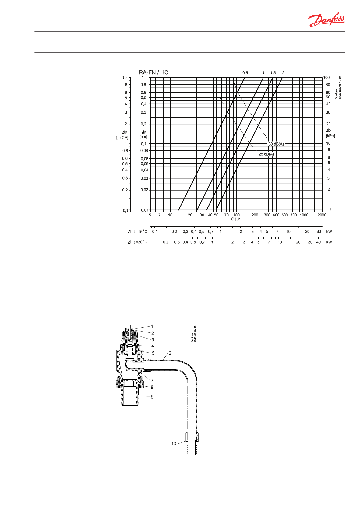
Capacities
Construction
Note:
As with any device which imposes a pressure
drop in the system, noise may occur under certain flow/pressure conditions.
RA-FN/HC
To ensure quiet operation, maximum pressure
drop should not exceed 30-35 kPa (3-3,5 mwg).
1. Gland seal
2. O-Ring
3. Pressure pin
4. Seal
5. Regulation spring
6. Elbow
7. Valve body
8. Union nut
9. Tail piece
10. Fitting
Danfoss Heating Solutions VDSXD302 © Danfoss 02/2013 3

Data Sheet Valve Body Type RA-FN/HC, Lock Shield Valve Type RLV-S/HC
Valve body and other metal
parts
O-ring EPDM
Valve cone NBR
Pressure pin and valve spring Steel/chrome
Elbow Copper
RLV-S/HC
Ms 58, brass
The valve bodies are nickle-plated on the outside.
The radiator thermostats consist of the thermostatic elements of the RA 2000 series and the
valve body RA-FN/HC.
The element and the valve body are ordered separately.
1. O-Ring
2. Cover cap
3. Shut off spindle
4. Valve body
5. Union nut
6. Tail piece
7. Elbow
8. Connection piece
Dimensions
Valve body and other metal parts Ms 58, brass
O-ring EPDM
Elbow Copper
UK valve body with thermostatic sensor RA 5054, type
RA-FN/HC
Angle lockshield valve body, type RLV-S
The valve bodies are nickle-plated on the outside.
4 VDSXD302 © Danfoss 02/2013 Danfoss Heating Solutions

Data Sheet Valve Body Type RA-FN/HC, Lock Shield Valve Type RLV-S/HC
Angle valve body with thermostatic sensor RA 5054, type
RA-FN/HC
Code number Type RA-FN 15/ RLV-S 15 D1 D2
013G3190
013G3191
013G3192
013G3189
013G3200
013G3195
013G3196
013G3197
013G3198
013G3199
RA-FN A 33, axial 21 R1/2 33 110 53 25 30
VRL-S 45, axial 21 24 R1/2 45 110 53 21 30
RA-FN A 33, Radial 21 R1/2 33 110 53 25 30
RLV-S 45, Radial 21 24 R1/2 45 110 53 21 30
RA-FN A 75, Axial 21 R1/2 75 110 53 25 30
RLV-S 75, Axial 21 24 R1/2 75 110 53 21 30
RA-FN A 75, Radial 21 R1/2 75 110 53 25 30
RLV-S 75, Radial 21 24 R1/2 75 110 53 21 30
RA-FN A 75, ½” con. 24 R1/2 75 104 53 25 30
RLV-S 75, ½” con. 24 24 R1/2 75 104 53 21 30
RA-FN UK 50, Axial 21 R1/2 50 110 66 27 30
RLV-S 45, Axial 21 24 R1/2 45 110 53 21 30
RA-FN UK 50, Radial 21 R1/2 50 110 66 27 30
RLV-S 45, Radial 21 24 R1/2 45 110 53 21 30
RA-FN UK 75, Axial 21 R1/2 75 110 66 27 30
RLV-S 75, Axial 21 24 R1/2 75 110 53 21 30
RA-FN UK 75, Radial 21 R1/2 75 110 66 27 30
RLV-S 75, Radial 21 24 R1/2 75 110 53 21 30
RA-FN UK 75, ½” con. 24 R1/2 75 104 66 27 30
RLV-S 75, ½” con. 24 24 R1/2 75 104 53 21 30
ISO 7-1
d2 S1 S2
L1 L2 L3
Arc.flats
Danfoss Heating Solutions VDSXD302 © Danfoss 02/2013 5

Data Sheet Valve Body Type RA-FN/HC, Lock Shield Valve Type RLV-S/HC
6 VDSXD302 © Danfoss 02/2013 Danfoss Heating Solutions

Data Sheet Valve Body Type RA-FN/HC, Lock Shield Valve Type RLV-S/HC
Danfoss Heating Solutions VDSXD302 © Danfoss 02/2013 7

Data Sheet Valve Body Type RA-FN/HC, Lock Shield Valve Type RLV-S/HC
Danfoss A/S
Heating Solutions
Haarupvaenget 11
8600 Silkeborg
Denmark
Phone: +45 7488 8000
Fax: +45 7488 8100
Email: heating.solutions@danfoss.com
www.heating.danfoss.com
Danfoss can accept no responsibility for possible errors in catalogues, brochures and other printed material. Danfoss reserves the right to alter its products without notice. This also applies to products
already on order provided that such alterations can be made without subsequential changes being necessary in specifications already agreed. All trademarks in this material are property of the respective
companies. Danfoss Heating Solutions and the Danfoss Heating Solutions logotype are trademarks of Danfoss A/S. All rights reserved.
8 VDSXD302 © Danfoss 02/2013 Danfoss Heating Solutions
 Loading...