

Installation Instructions
Remote Mounting of LCP
Items Supplied
LCP cable, IP 54
•
Gasket
•
Screws
•
Mounting plate bracket
•
Additional Items Required
Local control panel (LCP), order no. 132B0200
•
Safety Instructions
For important information about safety precautions for installation, refer to
VLT® HVAC Basic Drive FC 101 Quick Guide
•
VLT® DriveMotor FCP 106 and FCM 106 Operating
•
Instructions
WARNING
DISCHARGE TIME
The frequency converter contains DC-link capacitors, which
can remain charged even when the frequency converter is
not powered. Failure to wait the specified time after power
has been removed before performing service or repair work,
could result in death or serious injury.
1. Stop motor.
2. Disconnect AC mains, permanent magnet type
motors, and remote DC-link power supplies,
including battery back-ups, UPS, and DC-link
connections to other frequency converters.
3. Wait for the capacitors to discharge fully, before
performing any service or repair work. The duration
of waiting time is specified in Table 1.1 and
Table 1.2.
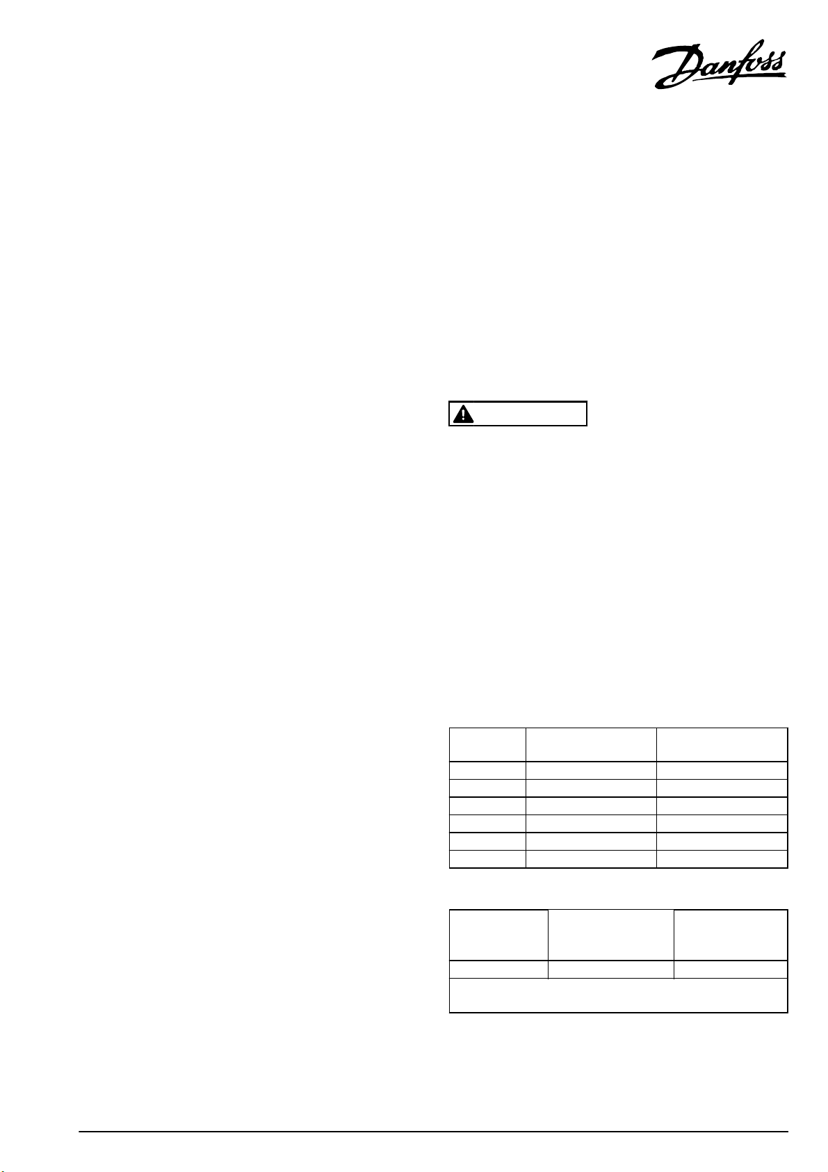
Voltage [V] Power range [kW] Minimum waiting time
[min]
3x200 0.25–3.7 4
3x200 5.5–11 15
3x400 0.37–7.5 4
3x400 11–90 15
3x600 2.2–7.5 4
3x600 11–90 15
Table 1.1 Discharge Time for FC 101
Voltage
[V]
3x400 0.55–7.5 4
High voltage can be present even when the warning LED indicator
Table 1.2 Discharge Time for FCP 106 and FCM 106
1) Power ratings relate to normal overload (NO), see VLT
FCP 106 and FCM 106 Operating Instructions.
Danfoss A/S © Rev. 2013-12-02 All rights reserved. MI18A202
Power Range
lights are off.
1)
[kW]
Minimum waiting
time
(min)
®
DriveMotor
Installation Instructions Remote Mounting of LCP
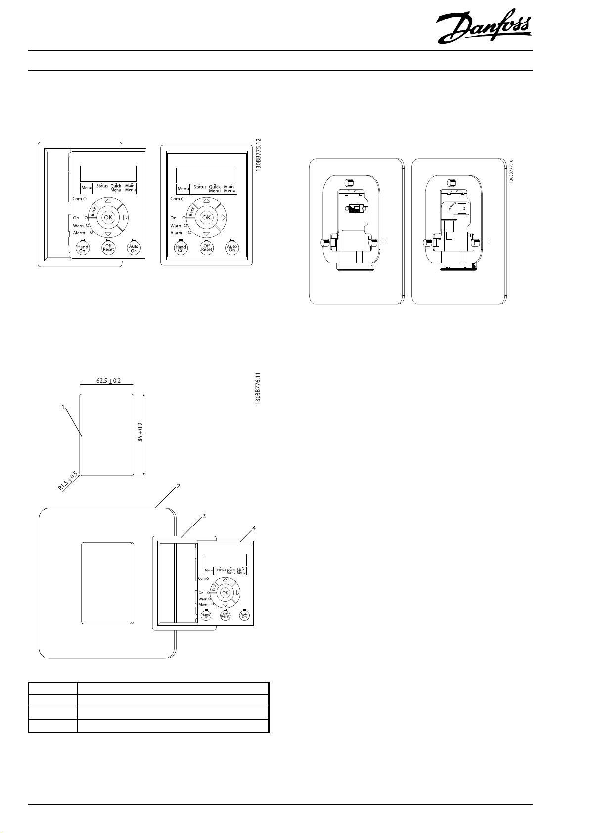
Mechanical Installation
1. Fit gasket on LCP, see Illustration 1.1.
Illustration 1.1 Fit Gasket on LCP
2. Cut out the panel, with the dimensions shown in
Illustration 1.2.
3. Position LCP with gasket onto the panel, as shown in
Illustration 1.2.
4. Position bracket on the back of the LCP, then slide
down. See Illustration 1.3
5. Fasten bracket to the LCP using the thread cutting
screws supplied. Tightening torque is 1.3 Nm.
Illustration 1.3 Position Bracket and Slide Down
1 Panel cut out. Panel thickness 1-3 mm
2Panel
3Gasket
4LCP
Illustration 1.2 Mounting of LCP on Panel
2
Danfoss A/S © Rev. 2013-12-02 All rights reserved. MI18A202

Installation Instructions Remote Mounting of LCP
Electrical Installation for FC 101
1. Connect LCP cable to the frequency converter, as
shown in Illustration 1.4.
2. Fasten connector to the frequency converter using
the thread cutting screws supplied. Tightening
torque is 1.3 Nm.
Electrical Installation for FCP 106 and FCM 106
1. For FCP 106 and FCM 106, remote mounting of the
LCP is intended for set-up and maintenance purposes
only, and is not suited for permanent installation.
Note that the LCP cable has ingress protection class
IP 54, and is not UL listed or UL recognised.
2. Connect LCP cable at the panel, as shown in
Illustration 1.5.
3. Connect LCP cable at the frequency converter as
shown in Illustration 1.6.
Illustration 1.4 Connection at Frequency Converter, FC 101
1LCP
2 Panel door
Illustration 1.5 Connection at Panel, FCP 106 and FCM 106
Illustration 1.6 Connection at Frequency Converter, FCP 106 and
FCM 106
MI18A202 Danfoss A/S © Rev. 2013-12-02 All rights reserved.
3

MI18A202132R0084 Rev. 2013-12-02
*MI18A202*
 Loading...