

Relief Valves Technical Information
1
2
1
2
1
2
1
2
Quick Reference
Thermal Relief Model No. Cavity Description Flow Pressure Page
CP208-4 SDC08-2 Relief Valve,
Thermal Relief,
Poppet Type
Direct Acting Model No. Cavity Description Flow Pressure Page
CP208-3 SDC08-2 Relief Valve,
Direct Acting,
CP200-3 SDC10-2 40 l/min
Poppet Type
1.1 l/min
[0.3 US gal/min]
30 l/min
[8 US gal/min]
[11 US gal/min]
415 bar
[6000 psi]
250 bar
[3600 psi]
250 bar
[3600 psi]
RV - 6
RV - 7
RV - 8
Direct Acting Model No. Cavity Description Flow Pressure Page
Quick Reference
Dierential Area Model No. Cavity Description Flow Pressure Page
RV08-DR SDC08-2 Relief Valve,
Direct Acting,
VEN 06 NCS06/2 40 l/min
VME 06 VME06 40 l/min
VME 07 VME07 50 l/min
VME 08 VME08 80 l/min
CP200-2 SDC10-2 Relief Valve,
CP208-1 SDC08-2 40 l/min
CP200-1 SDC10-2 75 l/min
CP201-1 CP12-2 150 l/min
Dampening,
Poppet Type
Dierential Area,
Poppet Type,
30 l/min
[8 US gal/min]
[11 US gal/min]
[11 US gal/min]
[13 US gal/min]
[21 US gal/min]
40 l/min
[11 US gal/min]
[11 US gal/min]
[20 US gal/min]
[40 US gal/min]
250 bar
[3600 psi]
250 bar
[3600 psi]
315 bar
[4500 psi]
315 bar
[4500 psi]
315 bar
[4500 psi]
350 bar
[5075 psi]
250 bar
[3600 psi]
250 bar
[3600 psi]
250 bar
[3600 psi]
RV - 9
RV - 10
RV - 11
RV - 12
RV - 13
RV - 14
RV - 15
RV - 16
RV - 17
BC332375370104en-000101 • February 2020
RV - 1
Relief Valves Technical Information
1
2
1
2
1
2
Quick Reference
Direct Acting Model No. Cavity Description Flow Pressure Page
CP210-1 SDC10-2 Relief Valve,
Direct Acting,
CP211-1 CP12-2 75 l/min
Pilot Operated Model No. Cavity Description Flow Pressure Page
CP210-2 SDC10-2 Relief Valve,
CP211-2 CP12-2 190 l/min
Spool Type,
Pilot Operated,
Spool Type
45 l/min
[12 US gal/min]
[20 US gal/min]
115 l/min
[30 US gal/min]
[50 US gal/min]
210 bar
[3000 psi]
40 bar
[600 psi]
350 bar
[5075 psi]
350 bar
[5075 psi]
RV - 18
RV - 19
RV - 20
RV - 21
Pilot Operated Model No. Cavity Description Flow Pressure Page
RV10-POP SDC10-2 Relief Valve,
Pilot Operated,
Poppet Type, with Free
Reverse Flow
Bi-Directional Model No. Cavity Description Flow Pressure Page
CP200-7 SDC10-2 Relief Valve,
Bi-directional
120 l/min
[32 US gal/min]
40 l/min
[11 US gal/min]
250 bar
[3625 psi]
250 bar
[3600 psi]
RV - 22
RV - 23
Quick Reference
BC332375370104en-000101 • February 2020
RV - 2
Relief Valves Technical Information
1
2
ATM.
V1
C1
V2
C2
Quick Reference
Dierential Area Model No. Cavity Description Flow Pressure Page
VSB 06-EN NCS06/2 Relief Valve,
Dierential Area,
VSB 12-EN NCS12/2 140 l/min
Poppet Type with Reverse
Free Flow Check
Dierential Area Model No. Cavity Description Flow Pressure Page
VSB 06-CN NCS06/2 Relief Valve,
Dierential Area,
VSB 12-CN NCS12/2 140 l/min
Poppet Type with Reverse
Free Flow Check,
Atmospheric Venting
80 l/min
[21 US gal/min]
[37 US gal/min]
80 l/min
[21 US gal/min]
[37 US gal/min]
350 bar
[5075 psi]
350 bar
[5075 psi]
350 bar
[5075 psi]
350 bar
[5075 psi]
RV - 24
RV - 25
RV - 26
RV - 27
Quick Reference
Cross-Over Model No. Cavity Description Flow Pressure Page
VA-E 06 none Relief Valve,
Cross-Over, Catalog HIC
CP220-1 none 75 l/min
CP221-1 none 150 l/min
40 l/min
[11 US gal/min]
[20 US gal/min]
[40 US gal/min]
210 bar
[3045 psi]
250 bar
[3600 psi]
250 bar
[3600 psi]
RV - 28
RV - 29
RV - 30
BC332375370104en-000101 • February 2020
RV - 3
Relief Valves Technical Information
1
1
Application Notes
APPLICATIONS
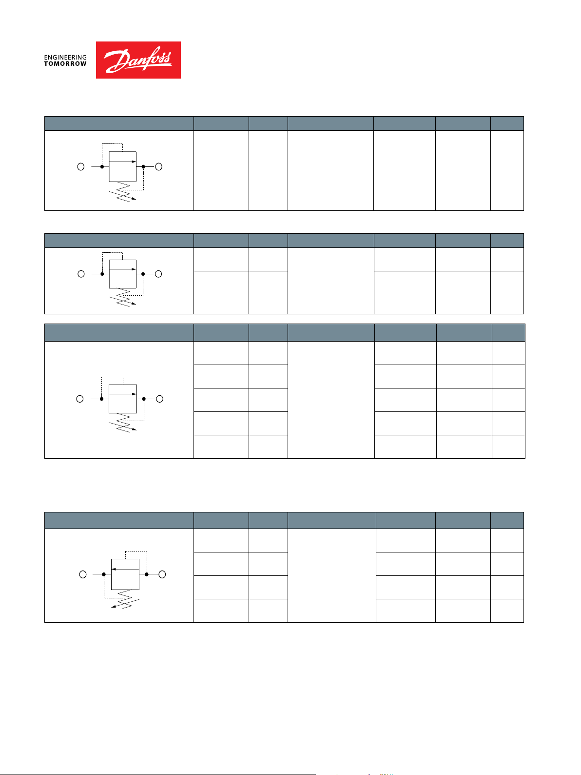
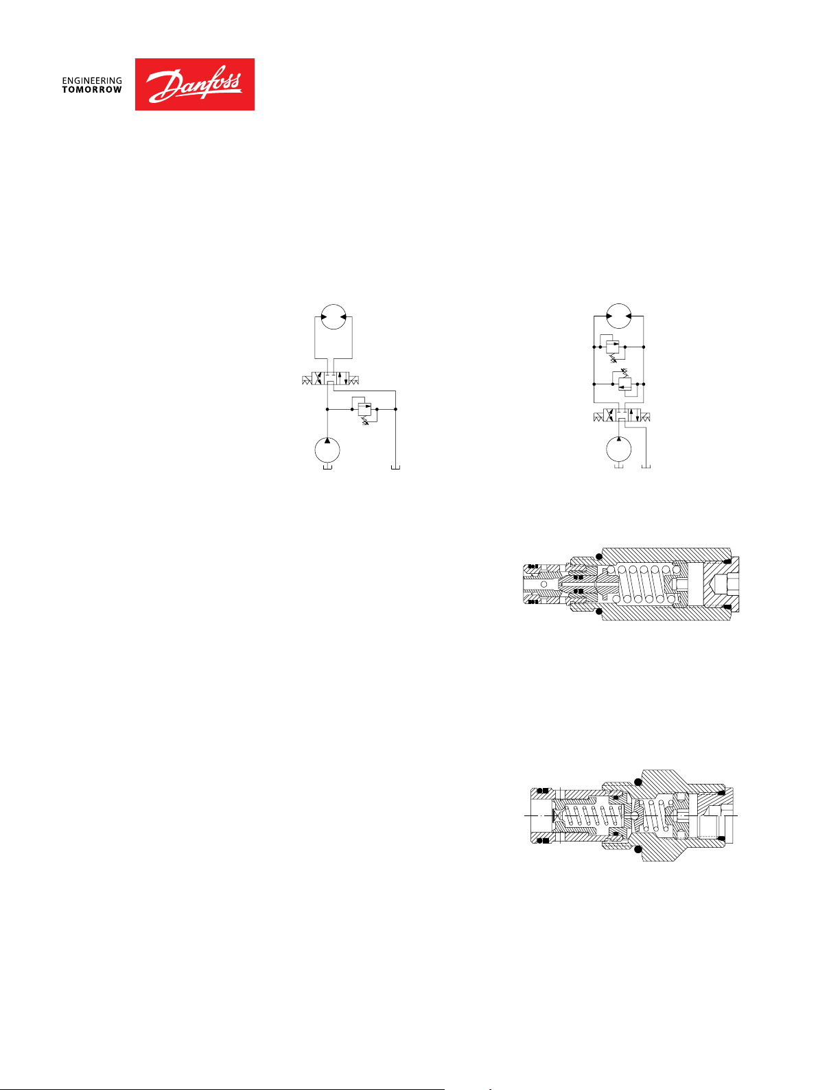
Relief valves are used as pressure limiting devices to protect hydraulic systems and
components. They are available in direct-acting poppet, dierential area poppet,
bi-directional poppet, and pilot-operated spool types.
Relief valves
OPERATION Direct-acting poppet
The direct-acting poppet blocks ow
from 1 to 2 until sucient pressure is
present at 1 to force the spring-opposed
poppet from it’s seat. This pressure is
commonly known as the crack pressure.
The valve will remain open until the
pressure drops to a level allowing the
spring to close the valve. This pressure is known as the re-seat pressure and is typically
70-80% of the crack pressure. The dierence between crack and re-seat pressure is
commonly referred to as hysteresis.
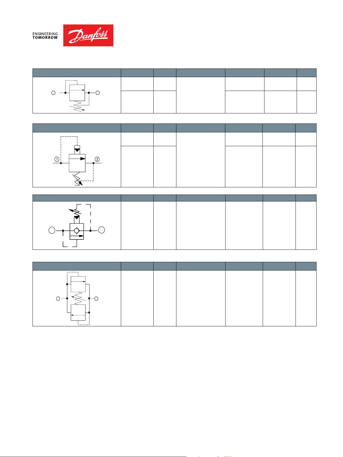
Dierential-area poppet
The dierential area poppet operates in the same manner except ow is blocked from 2
to 1 until sucient pressure is present at 2 to force the spring-opposed poppet from it’s
seat.
Advantages of direct-acting poppet and
dierential area poppet relief valves are:
· Fast response
· Contamination tolerant
· Low leakage
· Low cost
Direct acting poppet relief valve
2
Dierential area poppet relief valve
2
Applications Notes
BC332375370104en-000101 • February 2020
RV - 4
Relief Valves Technical Information
1
1
Application Notes
Applications Notes
OPERATION
(continued)
Because of these features some common applications for direct-acting and dierential
area poppet relief valves are:
· Main system relief valve if ow is relatively constant, or as a safety relief valve for
“spike clipping” to protect components from overpressure
· Work port cross-over relief to protect a cylinder or motor from overpressure
System Relief Valve Work Port Cross-Relief Valves
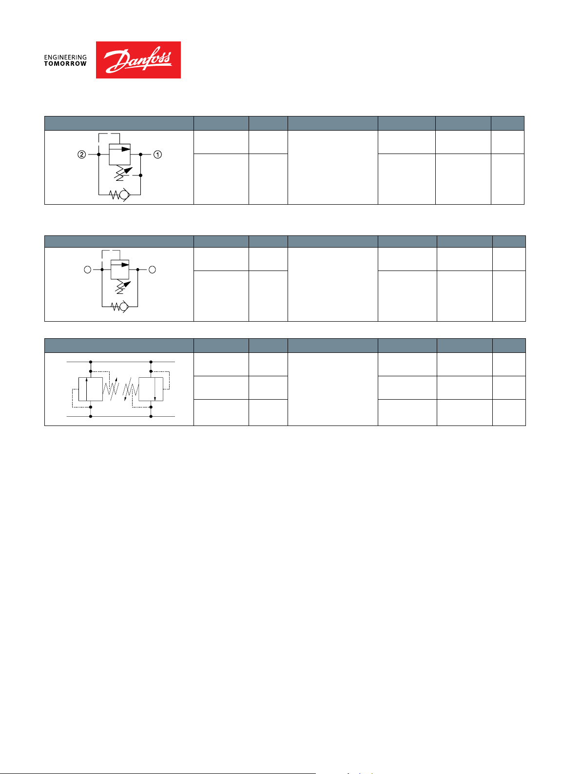
Bi-directional poppet
The bi-directional poppet is a dual
cross-over relief in a single cartridge.
Bi-directional poppet relief valve
When pressure at 1 exceeds the nominal
setting, the lower poppet acts as a
direct-acting relief valve and opens ow
from 1 to 2. When pressure at 2 exceeds
the nominal setting, the upper poppet
acts as a dierential area relief valve and
2
opens ow from 2 to 1 . Note that the
valve is designed so that the crack pressure is the same in either direction
A common application for a bi-directional relief valve is as a work port cross-over relief
where one bi-directional valve can replace two direct-acting valves.
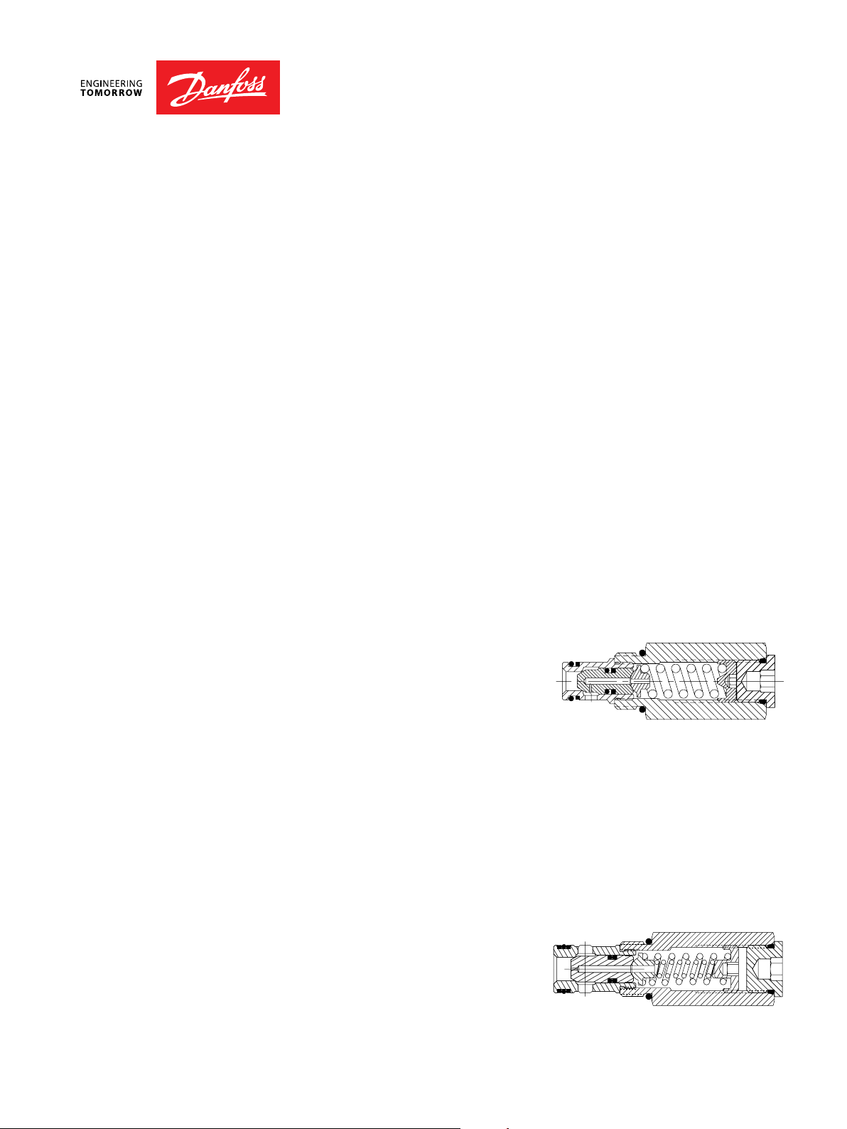
Pilot operated spool
The pilot operated spool blocks ow
Pilot operated spool relief valve
from 1 to 2 until sucient pressure is
present at 1 to force the pilot poppet
o it’s seat. This creates a pressure
dierential across the spool that causes
the spool to shift and open ow from 1
to 2.
2
Advantages of pilot-operated relief valves are:
· Smooth, stable response
· High ow and high pressure capability
· Precise pressure control with varying ow rates. Low pressure rise
· Low hysteresis
A common application for pilot-operated relief valves is as a main system relief where
high pressure or ow capability and/or extremely precise pressure control is required.
BC332375370104en-000101 • February 2020
RV - 5
Relief Valves Technical Information
1
2
=[
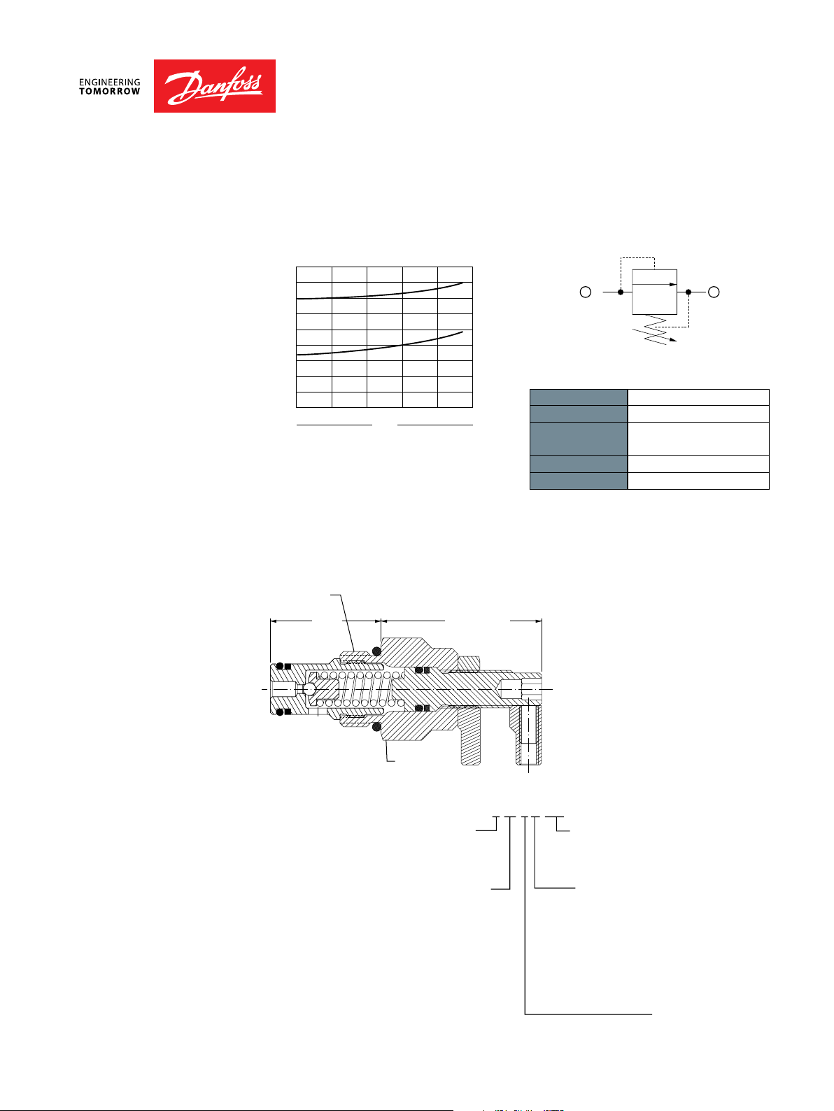
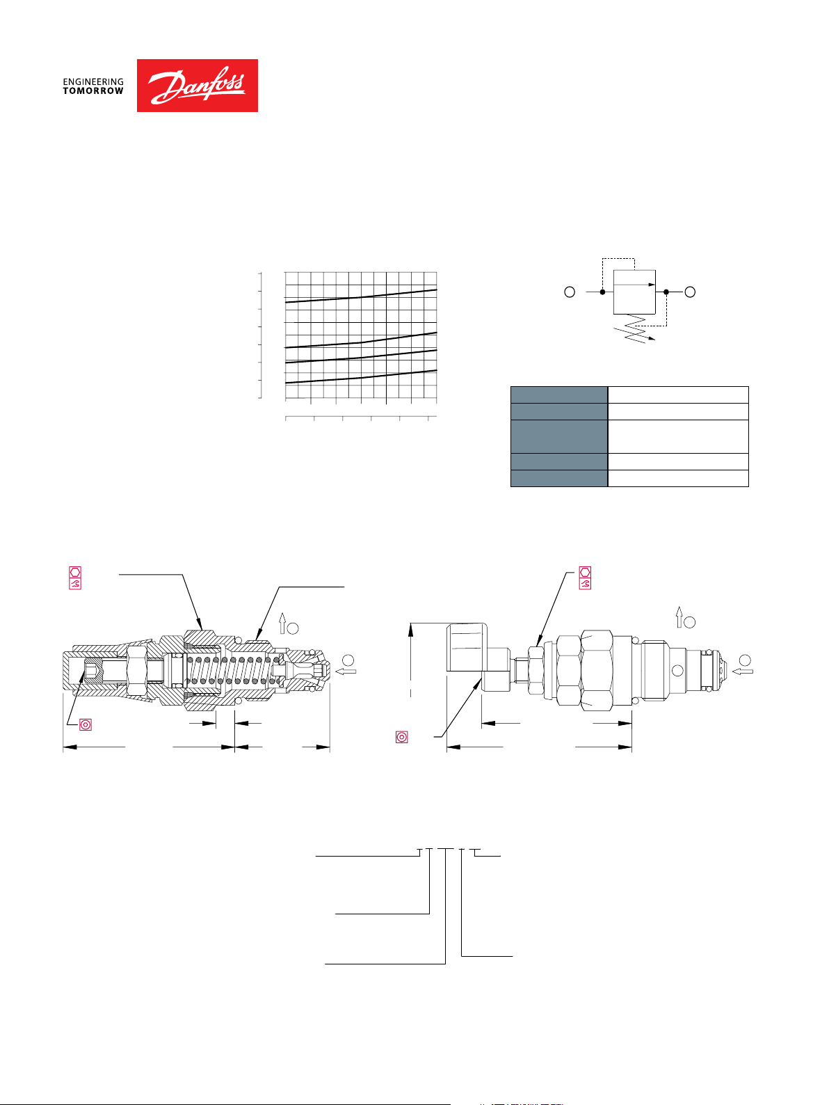
CP208-4-B-4S-E-C-300
K = Knob
Thermal Relief
CP208-4
OPERATION
SPECIFICATIONS
DIMENSIONS
mm [in]
This is a direct-acting poppet type thermal relief valve that relieves from 1 to 2.
Theoretical performance Schematic
psi bar
6527
5802
5076
4351
3626
2901
2176
1450
154 SUS (33 cSt) hyd. oil @ 100° F (38° C)
450
400
350
300
250
200
150
100
50725
0
US gal/min
L/min
0.4
0.1
0.8 1.21.6 2
Flow
0.2 0.3 0.4 0.5
Specications
Rated pressure 415 bar [6000 psi]
Rated ow 1.1 l/min [0.3 US gal/min]
Leakage 10 drops/min @ 80%
of pressure setting
Weight 0.23 kg [0.50 lb]
Cavity SDC08-2
Cross-sectional view
3/4-16 UNF
1
ORDERING
INFORMATION
Housing and portsHousing P/N
0=No Housing No Housing
DG2B =Al, 1/4 BSP SDC08-2-DG-2B
DG3B =Al, 3/8 BSP SDC08-2-DG-3B
4S =Al,#4 SAE CP08-2-4S
6S =Al,#6 SAE CP08-2-6S
Other housings available
BC332375370104en-000101 • February 2020
1.10
[27.8]
1.59
[40.3]
2
ht0.875 in
27-34 N•m
[20-25 lbf•ft]
Seals Seal kits
B = Buna-N 120221
V =Viton 120222
max.
Type E
adjustment
Type K
adjustment
Crack pressure
Code x 10 = psi
Example: 300 = 3000 psi
Adjustment ranges
bar psi
A = 2-103 [30-1500]
Standard 207 [1000]
B
7-207
Standard 103 [1500]
C =69-414 [1000-6000]
Standard 207 [3000]
Adjustment options
100-3000]
E = External
RV - 6
Relief Valves Technical Information
154 SUS (33 cSt) hyd. oil @ 100° F (38° C)
1 450
2 176
2 901
3 626
6
1
2
Adjustment option
[100-1000]
[200-2000]
[500-3600]
Seals
Housing and po
DG2
DG3
O
Direct Acting
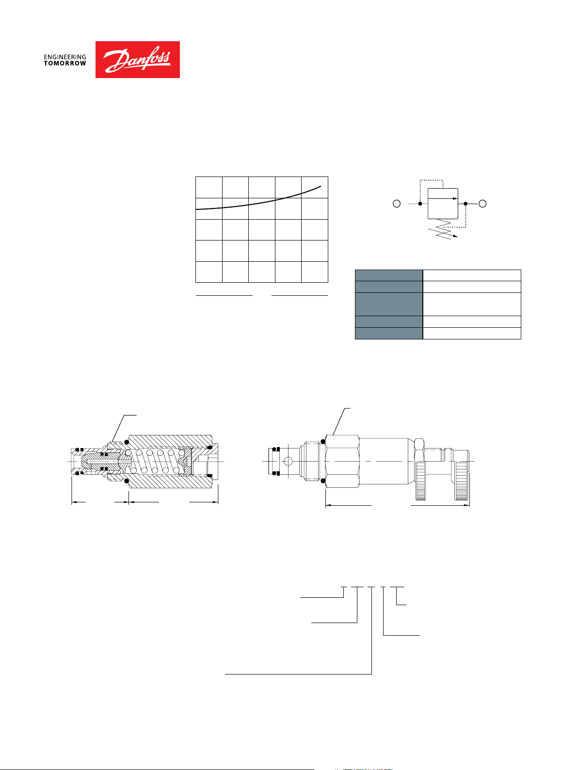
CP208-3
OPERATION
SPECIFICATIONS
DIMENSIONS
mm [in]
This is a direct-acting poppet type relief valve that relieves from 1 to 2.
Theoretical performance Schematic
psi bar
250
200
150
100
50
725
Specications
Rated pressure 250 bar [3600 psi]
0
8L/min
16 24 32 40
2.1US gal/min
Flow
4.2 6.3 8.5 10.
Rated ow 30 l/min [8 US gal/min]
Leakage 10 drops/min @ 80%
of pressure setting
Weight 0.15 kg [0.32 lb]
Cavity SDC08-2
Cross-sectional view
ORDERING
INFORMATION
BC332375370104en-000101 • February 2020
1
2
27.7
[1.09]
3/4-16 UNF
43.4
[1.71]
ther housings available
Type A
adjustment
Type F
adjustment
B=Buna-N 120221
V=Viton 120222
0=No Housing No Housing
B=Al,1/4 BSP SDC08-2-DG-2B
B=Al,3/8 BSP SDC08-2-DG-3B
4S =Al, #4 SAE CP08-2-4S
6S =Al, #6 SAE CP08-2-6S
A= Internal
E= External
F= Tamper resistant
K= Knob
rtsHousing P/N
Seal Kit
ht0.875 in
27-34 N.m
[20-25 lbf.ft]
68.3
max.
[2.69]
CP208-3-B-6S-A-C - 150
Type E
adjustment
Type K
adjustment
Crack pressure
Code x 10 = psi
Example: 150 = 1500 psi
Pressure range
A= 7-69
Standard 28 [400]
B= 14-138
Standard 69 [1000]
C= 35-248
Standard 103 [1500]
bar [psi]
RV - 7
Relief Valves Technical Information
1 450
2 176
2 901
3 626
9
1
2
A
]
]
]
Seals
Housing and po
DG3
DG4
O
Direct Acting
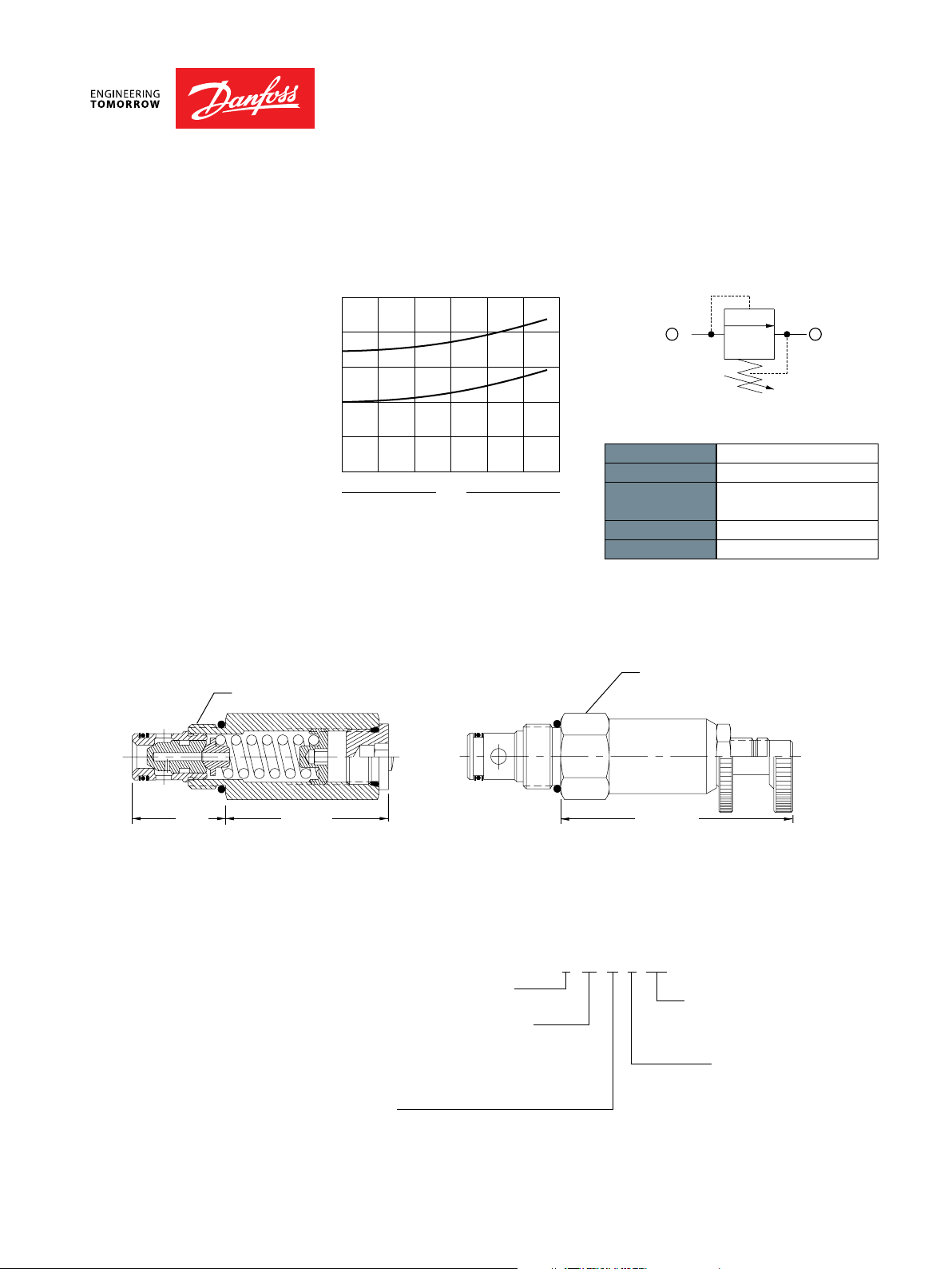
CP200-3
OPERATION
SPECIFICATIONS
DIMENSIONS
mm [in]
This is a direct-acting poppet type relief valve that relieves from 1 to 2.
Theoretical performance Schematic
psi bar
US gal/min
154 SUS (33 cSt) hyd. oil @ 100° F (38° C)
250
200
150
100
50725
0
10
L/min
20 30 40 50 60
2.6
5.3 7.9 10.6 13.2 15.
Flow
Specications
Rated pressure 250 bar [3600 psi]
Rated ow 40 l/min [11 US gal/min]
Leakage 10 drops/min @ 80%
of pressure setting
Weight 0.21 kg [0.47 lb]
Cavity SDC10-2
Cross-sectional view
7/8-14 UNF
1
2
31.8
[1.25]
55.9
[2.20]
ORDERING
INFORMATION
B=Buna-N 120073
V=Viton120074
0=No Housing No Housing
B=Al,3/8 BSP SDC10-2-DG-3B
B=Al,½ BSP SDC10-2-DG-4B
6S =Al, #6 SAE CP10-2-6S
8S =Al, #8 SAE CP10-2-8S
ther housings available
djustment option
A= Internal
E= External
F= Tamper resistant
K= Knob
BC332375370104en-000101 • February 2020
Type A
adjustment
Type F
adjustment
CP200-3-B-6S-A-C - 150
Seal kit
rt s Housing P/N
h 1.00 in
41-47 N.m
t
[30-35 lbf.ft]
Type E
adjustment
Type K
adjustment
80.0
max.
[3.15]
Crack pressure
Code x 10 = psi
Example: 150 = 1500 psi
Pressure range
A= 7-69 [100-1000
Standard 28 [400]
B= 17-172 [250-2500
Standard 69 [1000]
C= 41-248 [600-3600
Standard 103 [1500]
bar [psi]
RV - 8
Relief Valves Technical Information
1500
1000
3000
2000
2500
3500
n
1
2
Direct Acting
RV08-DR
OPERATION
SPECIFICATIONS
DIMENSIONS
mm [in]
22mm
35-40 Nm [26-30 lbf*ft]
Type F
Adjustment
This is a direct-acting, poppet-type relief valve that relieves from 1 to 2. It features a
highly damped poppet for smooth and stable response.
Theoretical performance Schematic
psi
bar
26 cSt[121 SUS]hyd.oil@50°C[122°F]
250
200
150
100
50
500
0
0
0
0
5
1.5
10
15
20
25
3
4.5
6
30
US gal/mi
7.5
l/min
Specications
Rated pressure 250 bar [3600 psi]
Rated ow 30 l/min [8 US gal/min]
Leakage 10 drops/min @ 80%
of pressure setting
Weight 0.10 kg [0.22 lb]
Cavity SDC08-2
Cross-sectional view
3/4-16 UNF 2A
Type K
Adjustment
2
13mm
7-9Nm [5-6 lbf*ft]
2
4mm
6 [0.24]
30 [1.18]54.3 [2.14]
ORDERING
INFORMATION
Pressure range
1 = 20-80 Bar [290-1150 psi]
2 = 35-160 Bar [500-2300 psi]
3 = 60-250 Bar [870-3600 psi]
Adjustment option
E = External
F =Tamper resistant
K = Knob
Crack pressure
Code = Setting in Bar
XXX = No specific setting
BC332375370104en-000101 • February 2020
1
Ø30.0 [1.18]
6mm
RV08-DR-1-E-XXX-B-4S
Type E
Adjustment
47.5 [1.87] MAX.
58.5 [2.30] MAX.
Housing and portsHousing P/N
00 =No Housing No Housing
DG2B= Al,1/4 BSPSDC08-2-DG-2B
DG3B= Al,3/8 BSPSDC08-2-DG-3B
4S =Al, #4 SAE CP08-2-4S
6S =Al, #6 SAE CP08-2-6S
Other housings available
Seals Seal Kit
B = Buna-N 354000119
V =Viton 354000219
1
RV - 9

Relief Valves Technical Information
P103 393E
1000
2000
3000
4000
5000
04
81
1
2
61.8
[2.43]
27 mm
44-50 N•m
[32-37 lbf•ft]
33.2
[1.31]
2
1
M 22 x 1.5
1
Direct Acting
VEN 06
OPERATION
SPECIFICATIONS
DIMENSIONS
mm [in]
This is a direct-acting, poppet-type relief valve that relieves from 1 to 2. It features a
highly damped poppet for smooth and stable response.
Theoretical performance Schematic
psi bar
26 mm °C [° F]²/sec (cSt) [124 SUS] @ 50 122
400
300
200
100
Specications
0
US gal/min
0
010203
02 46
Minimum setting value
l/min
0
0
Rated pressure 315 bar [4500 psi]
Rated ow 40 l/min [11 US gal/min]
Weight 0.20 kg [0.44 lb]
Cavity NCS06/2
Cross-sectional view
ORDERING
INFORMATION
Ty pe of adjustmen t
EN = External screw
M = Handwheel
Setting r ange
1 = 20 - 80 bar [290 - 1160 psi]
2 = 35 - 160 bar 508 2321[- psi]
3 = 70 - 315 bar 1015 4569[- psi]
To order this valve with a specic factory setting,contact your Danfoss ICS representative
BC332375370104en-000101 • February 2020
VEN 06 - M - 1 - DG3/8 -V - XXX
Housing and po rt sHousing P/N
0=No Housing No Housing
DG3/8 =AL, 3/8 BSP NCS06/2-DG-3/8
DG1/2 =AL,1/2 BSP NCS06/2-DG-1/2
DG6S=AL,#6 SAE NCS06/2-DG-6S
DG8S=AL,#8 SAE NCS06/2-DG-8S
Other housings available
Seals
V =Viton seals
Omit = Buna-N
Seal kit
230000380
230000060
RV - 10

Relief Valves Technical Information
P103 396E
1000
2000
3000
4000
5000
1
2
A
S
VME06-DG-3/8
Direct Acting
VME 06
OPERATION
SPECIFICATIONS
DIMENSIONS
mm [in]
This is a direct-acting, poppet-type relief valve that relieves from 1 to 2. It features a
highly damped poppet for smooth and stable response.
Theoretical performance Schematic
psi bar
26 mm °C [° F]
400
300
200
100
0
²/sec (cSt) [124 SUS] @ 50 122
i
1
4
m
US gal/min
0
0
0
Flow
n
2
m
i
l/min
u
12
8
3
16
4
Specications
Rated pressure 315 bar [4500 psi]
Rated ow 40 l/min [11 US gal/min]
e
u
l
a
v
g
n
i
t
t
e
s
m
Weight 0.13 kg [0.29 lb]
Cavity VME06
Cross-sectional view
ORDERING
INFORMATION
djustment
EN = External screw
M = Handwheel
MG = Handwheel (panel mounted)
etting r ange
1 = 25 - 70 bar [363-1015 psi]
2 = 35 - 170 bar 508 2466[- psi]
3 = 70 - 315 bar 1015 4569[- psi]
To order this valve with a specic factory setting,contact your Danfoss ICS representative
BC332375370104en-000101 • February 2020
I
VM E 06 -EN-2- DG3/8 -V - XXX
Seals
V =Viton seals
Omit = Buna-N
Housing and po rtsHousing P/N
00 =No Housing No Housing
DG3/8 =Al, 3/8 BSP
DG6S= Al,#6 SAE VME06-DG-6S
Other housings available
RV - 11

Relief Valves Technical Information
1000
2000
3000
4000
5000
1
2
55
[2.17]
32
[1.26]
Hex 27
54-60 N m
[40-44 lbf ft]
M 24 X 1.5
1
2
A
S
VME07-DG-1/2
1 = 25 - 80 bar [363-1160 psi
2 = 35 - 180 bar
3 = 70 - 315 bar
Direct Acting
VME 07
OPERATION
SPECIFICATIONS
DIMENSIONS
mm [in]
This is a direct-acting, poppet-type relief valve that relieves from 1 to 2. It features a
highly damped poppet for smooth and stable response.
Theoretical performance Schematic
P
psi bar
0
26 mm °C [° F]
400
300
200
100
0
²/sec (cSt) [124 SUS] @ 50 122
u
m
i
n
i
m
12.5
0
0
3
25
l/min
6
US g/min
ti
t
e
s
m
9
n
37.5
e
u
l
a
v
g
50
Specications
Rated pressure 315 bar [4500 psi]
Rated ow 50 l/min [13 US gal/min]
12
Weight 0.20 kg [0.44 lb]
Cavity VME07
Cross-sectional view
ORDERING
INFORMATION
BC332375370104en-000101 • February 2020
VM E07 - E- 2- DG1/2 -V - XXX
djustment
E =Internal screw
M = Handwheel
etting r ange
]
508 2611[- psi]
1015 4569[- psi]
Omit = Buna-N
Housing and po rtsHousing P/N
00 =No Housing No Housing
DG1/2 =Al, 1/2 BSP
DG8S= Al,#8 SAE VME07-DG-8S
Seals
V =Viton
Other housings available
To order this valve with a specic factory setting,contact your Danfoss ICS representative.
Seal kit
Consult factory
Consult factory
RV - 12

Relief Valves Technical Information
psi bar
80
[° F]
2
20
Flow
1
2
S
VME08-DG-12S
Direct Acting
VME 08
OPERATION
SPECIFICATIONS
DIMENSIONS
mm [in]
This is a direct-acting, poppet-type relief valve that relieves from 1 to 2. It features a
highly damped poppet for smooth and stable response.
Theoretical performance Schematic
26 mm °C
²/sec (cSt) [124 SUS] @ 50 12
m
i
n
i
m
20
0
0
4
40
l/min
8
US gal/min
ue
l
a
v
g
n
ti
t
e
s
m
u
60
12
16
Specications
Rated pressure 315 bar [4500 psi]
Rated ow 80 l/min [21 US gal/min]
Weight 0.35 kg [0.77 lb]
Cavity VME08
5000
4000
3000
2000
1000
400
300
200
100
0
0
Cross-sectional view
Hex 32
54-60 N•m
[40-44 lbf•ft]
M 30 X 1.5
2
1
46.5
[1.83]
ORDERING
INFORMATION
Adjustment
E =Internal screw
M = Handwheel
etting r ange
1 = 25 - 80 bar [363-1160 psi]
2 = 35 - 160 bar 508 2321[- psi]
3 = 70 - 315 bar 1015 4569[- psi]
To order this valve with a specic factory setting,contact your Danfoss ICS representative
BC332375370104en-000101 • February 2020
64.0
[2.52]
VM E08 - E- 2- DG3/4 -V -XXX
Housing and po rt sHousing P/N
00 =No Housing No Housing
DG3/4 =Al,3/4 BSP VME08-DG-3/4
DG12S =Al,#12 SAE
Other housings available
Seals
V =Viton
Omit = Buna-N
Seal kit
Consult factory
Consult factory
RV - 13

Relief Valves Technical Information
1,45
2,17
2,90
3,62
4,35
2
1
2
Seal
B = Buna-N
V
]
Dierential Area
CP200-2
OPERATION
SPECIFICATIONS
DIMENSIONS
mm [in]
This is a direct acting dierential area poppet type relief valve that relieves from 2 to 1.
Theoretical performance Schematic
psi bar
1
6
1
6
0
US gal/min
154 SUS (33 cSt) hyd. oil @ 100° F (38° C)
300
250
200
150
Press ure drop
100
50725
0
L/min
10
2.6
20 30 40 50
Flow
5.3 7.9 10.6 13.
Specications
Rated pressure 350 bar [5075 psi]
Rated ow 40 l/min [11 US gal/min]
Leakage 10 drops/min @ 80%
of crack pressure
Weight 0.21 kg [0.46 lb]
Cavity SDC10-2
Cross-sectional view
ORDERING
INFORMATION
s
=Viton 120016
Housing and portsHousing P/N
0=No Housing No Housing
DG3B=Al,3/8 BSP SDC10-2-DG-3B
DG4B=Al,1/2 BSP SDC10-2-DG-4B
6S =Al, #6 SAE CP10-2-6S
8S =Al, #8 SAE CP10-2-8S
Other housings available
BC332375370104en-000101 • February 2020
Seal kits
120015
CP200-2- B - 6S - E - D - 150
Adjustment options
A = Internal
F =Tamper resistant
E = External
K = Knob
Crack pressure
Code x 10 = psi
Example: 150 = 1500 psi
Adjustment ranges
D = 69-345 [1000-5000
Standard 103 [1500]
bar psi
RV - 14

Relief Valves Technical Information
US gal/min
1
2
A
]
]
]
Seals
Housing and po
DG2
DG3
O
Dierential Area
CP208-1
OPERATION
SPECIFICATIONS
DIMENSIONS
mm [in]
This is a direct acting dierential area poppet type relief valve that relieves from 2 to 1.
Theoretical performance Schematic
psi bar
6
1
6
0
725
154 SUS (33 cSt) hyd. oil @ 100° F (38° C)
250
200
150
100
Press ure drop
50
0
20L/min
5.3
Flow
10.6
Specications
Rated pressure 250 bar [3600 psi]
40
60
15.9
Rated ow 40 l/min [11 US gal/min]
Leakage 10 drops/min @ 80%
of pressure setting
Weight 0.15 kg [0.32 lb]
Cavity SDC08-2
Cross-sectional view
3/4-16 UNF
1
2
43.4
[1.71]
ORDERING
INFORMATION
B=Buna-N 120221
V=Viton120222
0=No Housing No Housing
B=Al, 1/4 BSP SDC08-2-DG-2B
B=Al, 3/8 BSP SDC08-2-DG-3B
4S =Al, #4 SAE CP08-2-4S
6S =Al, #6 SAE CP08-2-6S
ther housings available
djustment option
A= Internal
E= External
F= Tamper resistant
K= Knob
BC332375370104en-000101 • February 2020
type A
adjustment
type F
adjustment
CP20 8-1-B-6S-A-C - 150
Seal Ki t
rtsHousing P/N
h 0.875 in
27-34 N.m
t
[20-25 lbf.ft]
68.3
[2.69]
type E
adjustment
type K
adjustment
max.
Crack pressure
Code x 10 = psi
Example: 150 = 1500 psi
Pressure range
A= 7-69 [100-1000
Standard 28 [400]
B= 14-138 [200-2000
Standard 69 [1000]
C= 35-248 [500-3600
Standard 103 [1500]
bar [psi]
RV - 15

Relief Valves Technical Information
5.3US gal/min
1,45
2,17
2,90
3,62
100
10.6 15.9 21.1 26.4
1
2
[250-2000]
[600-3600]
Seals
Dierential Area
CP200-1
OPERATION
SPECIFICATIONS
DIMENSIONS
mm [in]
This is a direct acting dierential area poppet type relief valve that relieves from 2 to 1.
Theoretical performance Schematic
psi bar
6
1
6
0
725
154 SUS (33 cSt) hyd. oil @ 100° F (38° C)
250
200
150
100
Press ure drop
50
0
20L/min
40 60 80
Flow
Specications
Rated pressure 250 bar [3600 psi]
Rated ow 75 l/min [20 US gal/min]
Leakage 10 drops/min @ 80%
of pressure setting
Weight 0.21 kg [0.46 lb]
Cavity SDC10-2
Cross-sectional view
7/8-14 UNF
1
2
31.8
[1.25]
55.9
[2.20]
ORDERING
INFORMATION
B=Buna-N 120015
V=Viton 120016
Housing and portsHousing P/N
0=No Housing No Housing
DG3B=Al,3/8 BSP SDC10-2-DG-3B
DG4B=Al,1/2 BSP SDC10-2-DG-4B
6S =Al, #6 SAESDC10-2-6S
8S =Al, #8 SAESDC10-2-8S
Other housings available
Adjustment option
A= Internal
E= External
F= Tamper resistant
K= Knob
BC332375370104en-000101 • February 2020
Type A
adjustment
Type F
adjustment
CP200-1-B-8S-A-C-150
Seal kit
h 1.00 in
41-47 N.m
t
[30-35 lbf.ft]
80.0
max.
[3.15]
Type K
adjustment
Crack pressure
Code x 10 = psi
Example: 150 = 1500 psi
Pressure range
A= 7-55 [100-800]
Standard 28 [400]
B= 17-138
Standard 69 [1000]
C= 41-248
Standard 103 [1500]
bar [psi]
Type E
adjustment
RV - 16

Relief Valves Technical Information
1,16
1,45
1,74
2,03
1
2
Ad
[100-1000]
[250-2500]
[500-3600]
Seal
Housing and po
O
Dierential Area
CP201-1
OPERATION
SPECIFICATIONS
DIMENSIONS
mm [in]
This is a direct acting dierential area poppet type relief valve that relieves from 2 to 1.
Theoretical performance Schematic
psi bar
1
0
0
0
870
580
US gal/min
154 SUS (33 cSt) hyd. oil @ 100° F (38° C)
140
120
100
80
60
Press ure drop
40
20290
0
25
L/min
50 100 125 150 175
13.2
6.6
75
19.8
Flow
26.4
Specications
Rated pressure 250 bar [3600 psi]
Rated ow 150 l/min [40 US gal/min]
46.2
39.6
33
Leakage 10 drops/min @ 80%
of pressure setting
Weight 0.42 kg [0.92 lb]
Cavity CP12-2
Cross-sectional view
1-1/16-12 UN
1
2
44.5
[1.75]
61.2
[2.41]
ORDERING
INFORMATION
s Seal kit
B=Buna-N 120017
V=Viton 120018
0=No Housing No Housing
4B =Al, 1/2 BSP CP12-2-4B
6B =Al, 3/4 BSP CP12-2-6B
10S=Al, #10 SAE CP12-2-10S
12S=Al,#12 SAE CP12-2-12S
ther housings available
justment option
A= Internal
E= External
F= Tamper resistant
K= Knob
rtsHousing P/N
BC332375370104en-000101 • February 2020
Type A
adjustment
Type F
adjustment
h 1.25 in
t
CP201-1-B-12S-A-C - 150
68-75 N.m
[50-55 lbf.ft]
81.3
max
[3.20]
Crack pressure
Code x 10 = psi
Example: 150 = 1500 psi
Pressure range
A= 7-69
Standard 28 [400]
B= 17-172
Standard 69 [1000]
C= 35-248
Standard 103 [1500]
Type E
adjustment
Type K
adjustment
bar [psi]
RV - 17

Relief Valves Technical Information
2.6
US gal/min
5.3 7.9 10.6 13.2 15.9
1
2
[100-1400]
[500-2400]
Seals
Direct Acting
CP210-1
OPERATION
SPECIFICATIONS
DIMENSIONS
mm [in]
This is a direct acting spool-type relief valve that relieves from 1 to 2.
Theoretical performance Schematic
psi bar
2,031
1,740
1,450
1,160
870
580
154 SUS (33 cSt) hyd. oil @ 100° F (38° C)
140
120
100
80
60
Press ure drop
40
20290
0
L/min
20 30 40 50 60
10
Specications
Rated pressure 210 bar [3000 psi]
Rated ow 45 l/min [12 US gal/min]
Flow
Leakage 82 cm³/min [5 in³/min] @ 80%
of pressure setting
Weight 0.22 kg [0.48 lb]
Cavity SDC10-2
Cross-sectional view
7/8-14 UNF
1
2
31.8
[1.25]
55.9
[2.20]
ORDERING
INFORMATION
B=Buna-N 120015
V=Viton 120016
Housing and portsHousing P/N
0=No Housing No Housing
DG3B=Al, 3/8 BSP SDC10-2-DG-3B
DG4B=Al, 1/2 BSP SDC10-2-DG-4B
6S =Al, #6 SAE CP10-2-6S
8S =Al, #8 SAE CP10-2-8S
Other housings available
Adjustment option
A= Internal
E= External
F= Tamper resistant
K= Knob
BC332375370104en-000101 • February 2020
Type A
adjustment
Type F
adjustment
Seal kit
ht1.00 in
80.0
[3.15]
CP210-1-B-6S-A-C - 075
41-47 N.m
[30-35 lbf.ft]
max.
Crack pressure
Code x 10 = psi
Example: 075 = 750 psi
Pressure range
A= 3.4-28 [50-400]
Standard 17 [250]
B= 5.5-55 [80-800]
Standard 28 [400]
C= 6.9-97
Standard 52 [750]
D= 34-166
Standard 103 [1500]
bar [psi]
Type E
adjustment
Type K
adjustment
RV - 18

Relief Valves Technical Information
20
5
US gal/min
40
80
10
15
20
133
35
1
2
Direct Acting
CP211-1
OPERATION
SPECIFICATIONS
DIMENSIONS
mm [in]
This is a direct acting spool-type relief valve that relieves from 1 to 2.
Theoretical performance Schematic
psi bar
1000
0
600
0
0
154 SUS (33 cSt) hyd. oil @ 100° F (38° C)
69
56
42
28
Press ure drop
14
0
19
L/min
38 57
Flow
76 95
Specications
Rated pressure 40 bar [600 psi]
114
30
25
Rated ow 75 l/min [20 US gal/min]
Leakage 82 cm³/min [5 in³/min] @ 80%
of pressure setting
Weight 0.41 kg [0.90 lb]
Cavity CP12-2
Cross-sectional view
ht1.25 in
1 1/16-12UN
68-75 N•m
[50-55 lbf•ft]
Type A
1
adjustment
Type F
adjustment
Type E
adjustment
Type K
adjustment
2
44.5
[1.75]
ORDERING
INFORMATION
BC332375370104en-000101 • February 2020
62.2
[2.45]
CP211-1-B-10S-A-C-040
44.5
[1.75]
Pressure range
A = 0-10 bar [0-150 psi]
B = 3.4-34 bar [50-400 psi]
C = 5.2-41 bar [80-600 psi]
Housing and portsHousing P/N
0=No Housing No Housing
4B =Al, 1/2 BSP CP12-2-4B
6B =Al, 3/4 BSP CP12-2-6B
10S=Al, #10 SAE CP12-2-10S
12S=Al,#12 SAE CP12-2-12S
Other housings available
81.3
max
[3.20]
Crack pressure
Adjustment option
A = Internal
E = External
F =Tamper resistant
K = Knob
SealsSeal kit
B = Buna-N 120017
V =Viton 120018
Code x 10 = psi
Example: 040 = 400 psi
RV - 19

Relief Valves Technical Information
1,45
2,17
2,90
3,62
120
7
Seals
[200-1500]
[400-3000]
[400-5000]
Pilot Operated
CP210-2
OPERATION
SPECIFICATIONS
DIMENSIONS
7/8-14 UNF
This is a pilot operated spool type relief valve that relieves pressure from 1 to 2.
Theoretical performance Schematic
psi bar
6
1
6
0
725
154 SUS (33 cSt) hyd. oil @ 100° F (38° C)
250
200
150
100
Press ure drop
50
0
20L/min
40 60 80 100
10.6 15.9 21.1 26.4 31.
5.3US gal/min
Flow
Specications
Rated pressure 350 bar [5075 psi]
Rated ow 115 l/min [30 US gal/min]
Leakage 82 cm³/min [5 in³/min] @
207 bar [3000 psi]
Weight 0.18 kg [0.40 lb]
Cavity SDC10-2
Cross-sectional view
h 1.00 in
41-47 N.m
t
[30-35 lbf.ft]
1
2
31.8
[1.25]
41.7
[1.64]
ORDERING
INFORMATION
B=Buna-N 120015
V=Viton 120016
Housing and portsHousing P/N
0=No Housing No Housing
DG3B=Al,3/8 BSP SDC10-2-DG-3B
DG4B=Al,½ BSP SDC10-2-DG-4B
6S =Al, #6 SAE CP10-2-6S
8S =Al, #8 SAE CP10-2-8S
Other housings available
Adjustment option
A= Internal
E= External
F= Tamper resistant
K= Knob
BC332375370104en-000101 • February 2020
Type A
adjustment
Type F
adjustment
Seal kit
CP210-2-B-6S-A-C - 150
62.2
[2.45]
Type E
adjustment
Type K
adjustment
max.
Crack pressure
Code x 10 = psi
Example: 150 = 1500 psi
Pressure range
A= 14-69 [200-800]
Standard 28 [400]
B= 14-103
Standard 69 [1000]
C= 28-207
Standard 103 [1500]
D= 28-345
Standard 103 [1500]
bar [psi]
RV - 20

Relief Valves Technical Information
10.6US gal/min
21.1 31.7 42.3 52.8
Ad
[300-1500]
[400-3000]
[400-5000]
Housing and po
O
Pilot Operated
CP211-2
OPERATION
SPECIFICATIONS
DIMENSIONS
1-1/16-12 UN
1
2
45.7
[1.80]
This valve relieves from 1 to 2 and is a pilot operated spool type relief.
Theoretical performance Schematic
psi bar
4,351
3,626
2,901
2,176
1,450
154 SUS (33 cSt) hyd. oil @ 100° F (38° C)
300
250
200
150
Press ure drop
100
Specications
50
725
0
40L/min
80 120 160 200
Flow
Rated pressure 350 bar [5075 psi]
Rated ow 190 l/min [50 US gal/min]
Leakage 82 cm³/min [5 in³/min] @
207 bar [3000 psi]
Weight 0.17 kg [0.37 lb]
Cavity CP12-2
Cross-sectional view
h 1.25 in
t
Type A
adjustment
Type F
adjustment
37.1
[1.46]
57.9
[2.28]
68-75 N.m
[50-55 lbf.ft]
Type E
adjustment
Type K
adjustment
max.
ORDERING
INFORMATION
Seals Seal kit
B=Buna-N 120017
V=Viton 120018
0=No Housing No Housing
4B =Al, 1/2 BSP CP12-2-4B
6B =Al, 3/4 BSP CP12-2-6B
10S=Al, #10 SAE CP12-2-10S
12S=Al, #12 SAE CP12-2-12S
ther housings available
justment option
A= Internal
E= External
F= Tamper resistant
K= Knob
rtsHousing P/N
BC332375370104en-000101 • February 2020
CP211-2-B-12S-A-C - 150
Crack pressure
Code x 10 = psi
Example: 150 = 1500 psi
Pressure range
A= 14-69 [200-800]
Standard 28 [400]
B= 14-103
Standard 69 [1000]
C= 28-207
Standard 103 [1500]
D= 28-345
Standard 103 [1500]
bar [psi]
RV - 21

OPERATION
3200
US gal/min
2000
1600
1200
2400
2800
1
2
[10
.
4]
100 = 100 Bar [1500 psi]
E = Ex
F
K = Knob adjustmen
RV10 -POP -3-E-XXX-B-00
Pr
3=
e
SPECIFICATIONS
DIMENSIONS
Relief Valves Technical Information
Pilot Operated
RV10-POP
This is a pilot-operated poppet type relief valve that relieves pressure from 1 to 2, with an
integral free-ow check from 2 to 1.
Theoretical performance Schematic
psi
bar
300
240
180
120
800
60
400
0
0
P104 901
Cross-sectional view
Operating Envelope
26 cSt [121 SUS] hyd.oil@50°C [122°F]
0
4020
80
60
1680
100
24
120
32
l/min
Specications
Rated pressure 250 bar [3625 psi]
Rated ow 120 l/min [32 US gal/min]
Leakage 6 drops/min @ 80%
of pressure setting
Weight 0.22 kg [0.49 lb]
Cavity SDC10-2
24mm
35-40 Nm [26-30 lbf*ft]
Type F
adjustment
4mm
ORDERING
INFORMATION
65.6
[2.58]
4.54
[0.18]
32.9
[12.95]
essure Range
25-250 Bar[3 60-3600 psi]
Adjustment option
ternal adjustment
=Tamper resistant
t
Cracking pressure
Code = Std. setting in bar:
XXX = No specific setting
7/8 UNF 2A
6mm
60.3 max
[2.37 max]
13mm
7-9 Nm [5-6 lbf*ft]
Body and Ports
Omit = Cartridge only
6S = Al,#6 SAE
8S = Al,#8 SAE
DG3B = Al, 3/8 BSP
DG4B = Al, 1/2 BSP
Other housing available
Seals Seal Kit
B = Buna-N seals 354004019
V =Viton seals 354003419
2
Body Nomenclatur
No Body
CP10-2-6S
CP10-2-8S
SDC10-2-DG3B
SDC10-2-DG4B
26.5
1
Type K
adjustment
Ø30
[1. 18]
Type E
adjustment
71.3 max
[2.81 max]
BC332375370104en-000101 • February 2020
RV - 22

Relief Valves Technical Information
1,45
2,17
2,90
3,62
6
1
2
Seal
Ad
[250-2000]
[600-3600]
Housing and po
DG3
DG4
O
Bi-Directional
CP200-7
OPERATION
SPECIFICATIONS
DIMENSIONS
This is a bi-directional relief valve that relieves pressure from 1 to 2 and from 2 to 1.
Theoretical performance Schematic
psi bar
6
1
6
0
725
154 SUS (33 cSt) hyd. oil @ 100° F (38° C)
250
200
1
150
100
Press ure drop
50
0
2
8L/min
2.1US gal/min
1
2
16 24 32 40
Flow
4.2 6.3 8.5 10.
Specications
Rated pressure 250 bar [3600 psi]
Rated ow 40 l/min [11 US gal/min]
Leakage 5 cm³/min [0.3 in³/min] @ 80%
of pressure setting
Weight 0.20 kg [0.43 lb]
Cavity SDC10-2
Cross-sectional view
7/8-14 UNF
1
2
31.8
[1.25]
55.9
[2.20]
ORDERING
INFORMATION
s
B=Buna-N 120073
V=Viton 120074
0=No Housing No Housing
B=Al,3/8 BSP SDC10-2-DG-3B
B=Al,1/2 BSP 4
6S =Al, #6 SAE CP10-2-6S
8S =Al, #8 SAE CP10-2-8S
ther housings available
justment option
A= Internal
E= External
F= Tamper resistant
K= Knob
rtsHousing P/N
BC332375370104en-000101 • February 2020
h 1.00 in
41-47 N.m
t
[30-35 lbf.ft]
Type A
adjustment
Type F
adjustment
Seal kit
SDC10-2-DG- B
80.0
max.
[3.15]
CP200-7-B-8S-A-C - 150
Type E
adjustment
Type K
adjustment
Crack pressure
Code x 10 = psi
Example: 150 = 1500 psi
Pressure range
A= 7-41 [100-600]
Standard 28 [400]
B= 17-138
Standard 69 [1000]
C= 41-248
Standard 103 [1500]
bar [psi]
RV - 23

Relief Valves Technical Information
80
2000
3000
4000
5000
8
2
S
Dierential Area
VSB 06-EN
OPERATION
SPECIFICATIONS
DIMENSIONS
mm [in]
This is a direct-acting, dierential area, poppet-type relief valve that relieves from 2 to 1
with an integral free-ow check from 1 to 2.
Theoretical performance Schematic
psi bar
1000
0
26 mm °C [° F]
400
300
200
100
0
l/min
²/sec (cSt) [124 SUS] @ 50 122
nimum setting value
Mi
20 40 60
0510 15 20
Flow
US gal/min
Specications
Rated pressure 350 bar [5075 psi]
Rated ow 80 l/min [21 US gal/min]
Weight 0.22 kg [0.49 lb]
Cavity NCS06/2
Cross-sectional view
27 mm
44-50 N m
[32-37 lbf ft]
M 22 x 1.5
69.0
[2.72]
ORDERING
INFORMATION
etting range
1 = 20 - 80 bar [363 - 2031 psi]
2 = 70 - 210 bar [1015 - 3046 psi]
3 = 105 - 350 bar 1523[- 5076 psi]
To order this valve with a specic factory setting,contact your Danfoss ICS representative
BC332375370104en-000101 • February 2020
2
31.0
[1.21]
VSB 06-EN - 1 - 00 -V - XXX
Omit = Buna-N
Housing and po rtsHousing P/N
00 =No Housing No Housing
DG3/8=AL,3/8 BSP NCS06/2-DG-3/
DG1/2=AL, 1/2 BSP NCS06/2-DG-1/
DG6S =AL, #6 SAE NCS06/2-DG-6S
DG8S =AL, #8 SAE NCS06/2-DG-8S
Other housings available
Seals
V =Viton
1
Seal Kit
230000380
230000060
RV - 24

Relief Valves Technical Information
1000
2000
3000
4000
5000
5140
90.7
[3.57]
38 mm
64-70 Nm•
[47-52 lbfft]•
41.3
[1.63]
2
1
M 33 x 2
S
Dierential Area
VSB 12-EN
OPERATION
SPECIFICATIONS
DIMENSIONS
This is a direct-acting, dierential area, poppet-type relief valve that relieves from 2 to 1
with an integral free-ow check from 1 to 2.
Theoretical performance Schematic
psi bar
0
26 mm °C [° F]
400
300
200
100
0
l/min
²/sec (cSt) [124 SUS] @ 50 122
Minimum setting
35 70 10
010203035
Flow
US gal/min
v
lue
a
Specications
Rated pressure 350 bar [5075 psi]
Rated ow 140 l/min [37 US gal/min]
Weight 0.60 kg [1.32 lb]
Cavity NCS12/2
Cross-sectional view
ORDERING
INFORMATION
etting range
1 = 25 - 170 bar [363 - 2466 psi]
2 = 70 - 270 bar [1015 - 3916 psi]
3 = 105 - 350 bar 1523[- 5076 psi]
BC332375370104en-000101 • February 2020
VSB 12-EN - 1 - 00 -V - XXX
Omit = Buna-N
Housing and portsHousing P/N
00 =No Housing No Housing
DG1/2=AL,1/2 BSP NCS12/2-DG-1/2
DG3/4=AL,3/4 BSP NCS12/2-DG-3/4
DG8S =AL, #8 SAE NCS12/2-DG-8S
DG12S= AL,#12 SAE NCS12/2-DG-12S
Other housings available
Seals
V =Viton
Seal Kit
230000470
230000120
RV - 25

Relief Valves Technical Information
80
1000
2000
3000
4000
5000
1
2
ATM.
8
2
S
Dierential Area
VSB 06-CN
OPERATION
SPECIFICATIONS
DIMENSIONS
mm [in]
This is a direct-acting, dierential area, atmospherically-vented, poppet-type relief valve
that relieves from 2 to 1 with an integral free-ow check from 1 to 2.
Theoretical performance Schematic
psi bar
0
26 mm °C [° F]
400
300
200
100
0
l/min
²/sec (cSt) [124 SUS] @ 50 122
nimum setting value
Mi
20 40 60
0510 15 20
Flow
US gal/min
Specications
Rated pressure 350 bar [5075 psi]
Rated ow 80 l/min [21 US gal/min]
Weight 0.29 kg [0.64 lb]
Cavity NCS06/2
Cross-sectional view
27 mm
44-50 Nm·
[32-37 lbfft]·
M 22 x 1.5
1
2
87.0
[3.43]
31.0
[1.21]
ORDERING
INFORMATION
etting range
1 = 25 - 140 bar [363 - 2031 psi]
2 = 70 - 210 bar [1015 - 3046 psi]
3 = 105 - 350 bar 1523[- 5076 psi]
BC332375370104en-000101 • February 2020
To order this valve with a specic factory setting,contact your Danfoss ICS representative
VSB 06-CN - 1 - 00 -V - XXX
Omit = Buna-N
Housing and po rt sHousing P/N
00 =No Housing No Housing
DG3B =AL, 3/8 BSP NCS06/2-DG-3/
DG4B =AL, 1/2 BSP NCS06/2-DG-1/
DG6S =AL, #6 SAE NCS06/2-DG-6S
DG8S =AL, #8 SAE NCS06/2-DG-8S
Other housings available
Seals
V =Viton
Seal Ki t
230000380
230000060
RV - 26

Relief Valves Technical Information
1000
2000
3000
4000
5000
5140
S
S
Dierential Area
VSB 12-CN
OPERATION
SPECIFICATIONS
DIMENSIONS
mm [in]
This is a direct-acting, dierential area, atmospherically-vented, poppet-type relief valve
that relieves from 2 to 1 with an integral free-ow check from 1 to 2.
Theoretical performance Schematic
psi bar
0
26 mm °C [° F]
400
300
200
100
0
l/min
²/sec (cSt) [124 SUS] @ 50 122
Minimum setting
35 70 10
010203035
Flow
US gal/min
v
2
ATM.
lue
a
Specications
Rated pressure 350 bar [5075 psi]
Rated ow 140 l/min [37 US gal/min]
Weight 0.75 kg [1.65 lb]
Cavity NCS12/2
Cross-sectional view
38 mm
64-70 Nm•
[47-52 lbfft]•
M 33 x 2
1
127.9
[5.03]
ORDERING
INFORMATION
etting range
1 = 25 - 170 bar [363 - 2466 psi]
2 = 70 - 270 bar [1015 - 3916 psi]
3 = 105 - 350 bar 1523[- 5076 psi]
To order this valve with a specic factory setting,contact your Danfoss ICS representative
BC332375370104en-000101 • February 2020
VSB 12-CN - 1 - 00 -V - XXX
Omit = Buna-N
Housing and po rt sHousing P/N
00 =No Housing No Housing
DG1/2=AL,1/2 BSP NCS12/2-DG-1/2
DG3/4=AL,3/4 BSP NCS12/2-DG-3/4
DG8S =AL, #8 SAE NCS12/2-DG-8S
DG12S =AL, #12 SAE NCS12/2-DG-12
Other housings available
2
41.1
[1.62]
Seals
V =Viton
1
Seal Kit
230000470
230000120
RV - 27

Relief Valves Technical Information
1000
2000
3000
4000
5000
m
Ad
refer to
fo
T
Cross-Over
VA-E 06
OPERATION
SPECIFICATIONS
DIMENSIONS
mm [in]
justment option E shown,
VME 06 catalog page
r other options
This valve is an inline cross relief. It uses two VME 06 direct-acting relief valves.
Theoretical performance Schematic
psi bar
400
300
200
100
0
²/sec (cSt) [124 SUS] @ 50 122
26 mm °C [° F]
lu
a
v
g
tin
t
e
s
m
u
m
i
n
i
1
4
m
8
l/min
2
US gal/min
12
3
0
0
0
Flow
e
16
4
V1
V2
Specications
Rated pressure 210 bar [3045 psi]
Rated ow 40 l/min [11 US gal/min]
Weight 1.11 kg [2.45 lb]
Cavity none
Cross-sectional view
166.0[6.54]
70.0 [2.76]
18.0 [0.71] 34.0 [1.34]
Ø6.5 [0.26]
2THRU HOLES
35.0 [1.38]
C1
C2
35.0 [1.38]50.0 [1.97]
7.5[0.30]
7.5[0.30] 55.0 [2.17]
ORDERING
INFORMATION
Adjustment option
EN =External screw
M= Handwheel
Setting range
1 = 25 - 70 bar [360 - 1000 psi]
2 = 35 - 170 bar510 2500[- psi]
3 = 70 - 315 bar 1000 4500[- psi]
o order this valve with a specic factory setting,contact your Danfoss ICS representative
BC332375370104en-000101 • February 2020
13 mm
13-17Nm[9-12 lbf ft]
VA -E 06 - EN - 2 - LG -V - XXX
Seals Seal kit
V=Viton
Omit Consult factory
=Buna-N
Housing and port s
LG = AL,3/8 BSP
Consult factory
4m
RV - 28

Relief Valves Technical Information
1,45
2,17
2,90
3,62
4
31.8
88.9 [3.50]
[250-2000]
[600-3600]
Seal
Housing and po
O
Cross-Over
CP220-1
OPERATION
SPECIFICATIONS
DIMENSIONS
mm [in]
[1.25]
This valve is an inline cross relief. It uses two CP200-1 dierential area relief valves.
Theoretical performance Schematic
psi bar
6
250
1
200
6
150
100
0
Press ure drop
725
154 SUS (33 cSt) hyd. oil @ 100° F (38° C)
50
0
20L/min
40 60 80 100
5.3US gal/min
10.6 15.9 21.1 26.
Flow
V1
V2
Specications
Rated pressure 250 bar [3600 psi]
Rated ow 75 l/min [20 US gal/min]
Weight 0.82 kg [1.80 lb]
Cavity none
Cross-sectional view
15.9
[0.63]
30.2
[1.19]
6.4
[0.25]
19.1
[0.75]
82.6 [3.25]
C1
C2
V1
57.2
[2.25]
V2 C2
76.2
[3.00]
ORDERING
INFORMATION
3B =Al, 3/8 BSP 221743
4B =Al, 1/2 BSP 221744
6S =Al, #6 SAE 220216
8S =Al, #8 SAE 220217
ther housings available
s
B=Buna-N 120072
V=Viton 120161
Adjustment option
A= Internal
E= External
F= Tamper resistant
K= Knob
rtsHousing P/N
BC332375370104en-000101 • February 2020
38.1
[1.50]
V1
V2
C1
C2
58.7
[2.31]
CP220-1-8S-B-0-A-C-150
Seal kit
8.6
[0.34]
C1
186.9
[7.36]
Crack pressure
Code x 10 = psi
Example: 150 = 1500 psi
Pressure range
A= 7-55 [100-800]
Standard 28 [400]
B= 17-138
Standard 69 [1000]
C= 41-248
Standard 103 [1500]
bar [psi]
RV - 29

Relief Valves Technical Information
1,45
2,17
2,90
3,62
200
8
i
Cross-Over
CP221-1
OPERATION
SPECIFICATIONS
DIMENSIONS
mm [in]
V1
V2
63.5
[2.50]
This valve is an inline cross relief. It uses two CP201-1 dierential area relief valves.
Theoretical performance Schematic
psi bar
6
1
6
0
725
154 SUS (33 cSt) hyd. oil @ 100° F (38° C)
250
200
150
100
Press ure drop
50
0
40L/min
21.1 31.7 42.3 52.
10.6US gal/min
80 120 160
Flow
V1
V2
Specications
Rated pressure 250 bar [3600 psi]
Rated ow 150 l/min [40 US gal/min]
Weight 2.25 kg [4.95 lb]
Cavity none
Cross-sectional view
101.6 [4.00]
88.9 [3.50]
44.5
[1.75]
25.4
[1.00]
12.7
[0.50]
25.4
[1.00]
57.2
[2.25]
88.9
[3.50]
114.3
[4.50]
62.7
[2.47]
38.9
[1.53]
V1 C1
V2
C2
11.9
[0.47]
C1
C2
234.7
[9.24]
C1
C2
ORDERING
INFORMATION
Housings & Ports
6B: 3/4 BSP, AL
8B: 1 BSP, AL
12S: #12 SAE, AL
16S: #16 SAE, AL
Seal Option
Code Seal Material Seal kit
B Buna 120017
V Viton 120018
BC332375370104en-000101 • February 2020
Housing P/N
221742
221690
220223
220222
CP221-1 -
16S
- B - 0 -
Adjustment Option
A
Internal
E
External
F
Tamper Resistant
K
Knob
A
- C - 150
Cracking Pressure
Code x 10 = psi
Example: 150 = 1500 ps
Pressure Range
bar [psi]
A = 7-69 [100-1000]
Standard 28 [400]
B = 17-172 [250-2500]
Standard 69 [1000]
C = 41-248 [500-3600]
Standard 103 [1500]
RV - 30
 Loading...