

Data Sheet
Hand operated regulating valve
Type REG-SA SS and REG-SB SS
Assures favorable ow characteristics in harsh operating surroundings
In certain specic areas such as outdoor
applications and corrosive atmospheres, such
as coastal installations, there is a need for high
surface protection to prevent failure due to
corrosion.
Today's food safety standards often call for daily
treatment with detergents to protect against
bacteria growth, again producing a need for
high surface protection.
REG-SA SS and REG-SB SS are angle-way and
straight-way hand-operated regulating valves,
which act as normal stop valves in closed
position.
The valves are designed to meet the strict
quality requirements on refrigerating
installations specied by the international
classication societies and are carefully
designed to present favourable ow conditions
and accurate linear characteristics.
The valves are equipped with vented cap and
have internal backseating enabling the spindle
seal to be replaced with the valve still under
pressure.
AI234986440271en-000601

Hand operated regulating valve, type REG-SA SS and REG-SB SS
Features
• Applicable to HCFC, HFC, R717 (Ammonia), R744 (CO2), Propane, Butane, Iso-Butane and Ethane.
• R717 Heat Pump and Propylene applications with replaced O-ring.
• Designed to give favourable ow conditions.
• Internal backseating enables replacement of the spindle seal whilst the valve is active, i.e. under pressure
• Housing is made of special cold resistant stainless steel approved for low temperature operations.
• Easy to disassemble for inspection and service.
• Butt-weld DIN and ANSI connections.
• Max. operating pressure: 52 bar (754 psig)
• Temperature range: -60 °C / +150 °C (-76 °F / +302 °F)
• Compact and light valves for easy handling and installation
• Classication: DNV, CRN, BV, EAC etc. To get an updated list of certication on the products please contact your
local Danfoss Sales Company.
© Danfoss | Climate Solutions | 2021.02 AI234986440271en-000601 | 2

Hand operated regulating valve, type REG-SA SS and REG-SB SS
Media
Refrigerants
Refrigerants
Applicable to HCFC, HFC, R717 (Ammonia), R744 (CO2), Propane, Butane, Iso-Butane and Ethane. R717 Heat Pump
and Propylene applications with replaced O-ring.
For further information please contact your local Danfoss Sales Company.
New refrigerants
Danfoss products are continually evaluated for use with new refrigerants depending on market requirements.
When a refrigerant is approved for use by Danfoss, it is added to the relevant portfolio, and the R number of the
refrigerant (e.g. R513A) will be added to the technical data of the code number. Therefore, products for specic
refrigerants are best checked at store.danfoss.com/en/, or by contacting your local Danfoss representative.
© Danfoss | Climate Solutions | 2021.02 AI234986440271en-000601 | 3
-70 -50 -30 -10 10 30 50 70 90 110 130 150
-94 -58 -22 14 50 86 122 158 194 230 266 302
˚C
˚F
0
73
145
218
290
363
435
508
580
653
725
798
psi
0
5
10
15
20
25
30
35
40
45
50
55
bar
Temperature
Pressure
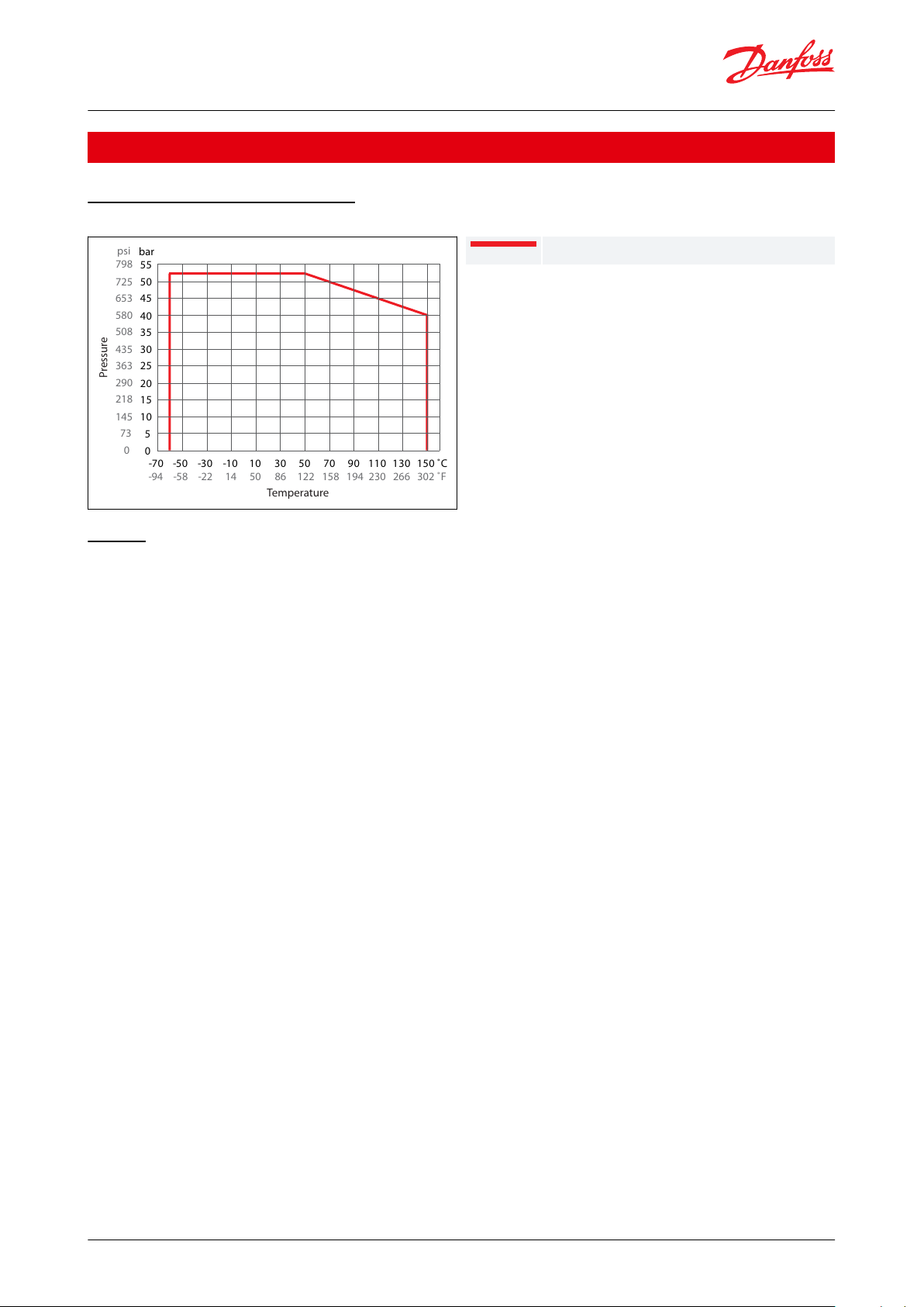
REG-SA SS/REG-SB SS DN15-DN40
Hand operated regulating valve, type REG-SA SS and REG-SB SS
Product specication
Pressure and temperature range
Figure 1: Pressure and temperature range graph
Design
Housing
Made of stainless steel approved for low temperature operations.
The cone
The valves are available in two dierent versions – REG-SA SS with an A cone and REG-SB SS with a B cone. The A
cone is designed for expansion lines, while the B cone is designed for regulating purposes e.g. liquid lines.
The valve cone is designed to ensure perfect regulation and provide an extensive regulating area. Irrespective of the
refrigerant used, it is easy to obtain the correct capacity. A cone seal ring provides perfect sealing at a minimum
closing momentum.
The valve cone can be turned on the spindle, thus there will be no friction between the cone and the seat when the
valve is opened and closed.
Made of polished stainless steel, ideal for O-ring sealing. Furthermore, parts of the spindle are heat treated to obtain
anti-abrasive/adhesive properties.
Packing gland - REG-SA SS and REG-SB SS
The stainless steel packing gland comprises a spring loaded seal packing gland which ensures a perfect tightness in
the range: -60 °C / +150 °C (-76 °F / +302 °F).
The packing glands are equipped with a scraper ring to prevent penetration of dirt and ice into the packing gland.
Installation
Install the valve with the spindle up or in horizontal position. The ow must be directed towards the cone.
The valve is designed to withstand high internal pressure. However, the piping system in general should be
designed to avoid liquid traps and reduce the risk of hydraulic pressure caused by thermal expansion.
For further information refer to installation guide for REG-SA SS and REG-SB SS.
© Danfoss | Climate Solutions | 2021.02 AI234986440271en-000601 | 4
R
E
G
U
L
A
T
I
N
G
V
A
L
V
E
R
E
G
-
S
A
S
S
Description
Values
Temperature range
-60 °C - +150 °C (-76 °F -+302°F)
Max working pressure
52 bar (754 psig)
T
ØD
Danfoss
A148B15.10
Size
OD
T
15mm21.3
2.3½in.
0.839
0.09120mm
26.9
2.3¾in.
1.059
0.09125mm
33.7
2.61in.
1.327
0.10332mm
42.4
2.61¼in.
1.669
0.10240mm
48.3
2.61½in.
1.902
0.103
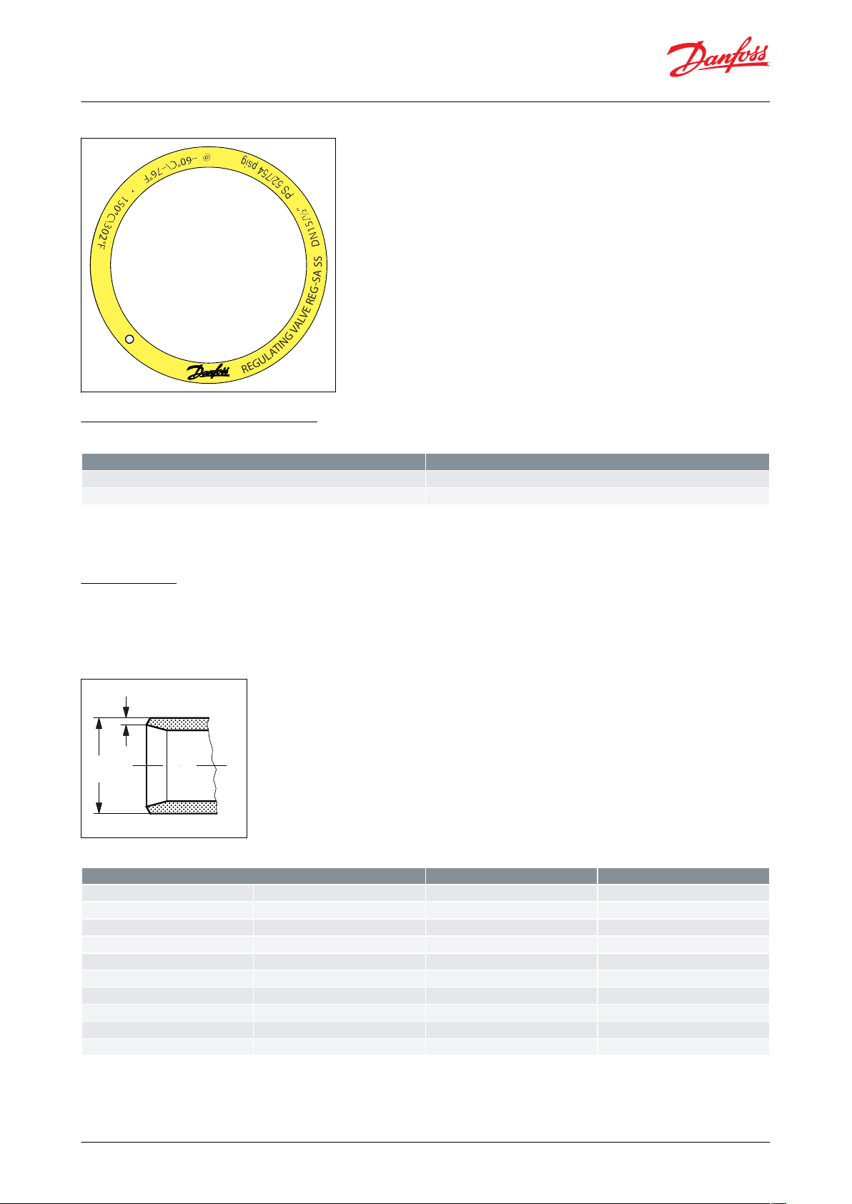
Hand operated regulating valve, type REG-SA SS and REG-SB SS
Figure 2: Example of marking ring, REG-SA SS
Pressure and temperature data
Table 1: Pressure and temperature
Flow coecients
Flow coecients for fully opened valves from kv = 0.15 to 80 m3/h (Cv = 0.17 to 92.5 USgal/min).
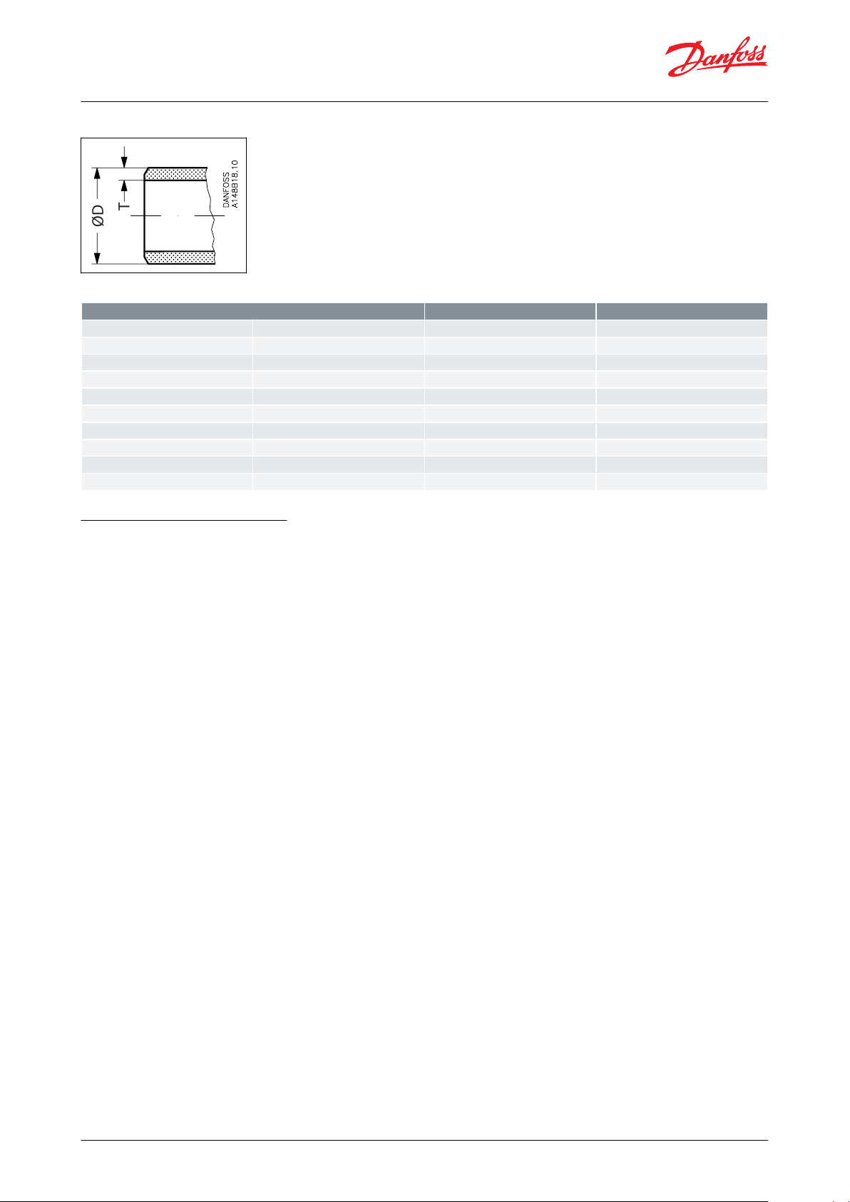
Connections
Available with the following connections:
Butt-weld DIN (EN 10220): DN 15 - 40 (½ - 1½ in.)
Butt-weld ANSI (B 36.19M): DN 15 - 40 (½ - 1½ in.)
Figure 3: DIN
Table 2: Butt-weld DIN (EN 10220)
© Danfoss | Climate Solutions | 2021.02 AI234986440271en-000601 | 5
T
ØD
Size
OD
T
15mm21.3
2.8½in.
0.839
0.1120mm
26.9
2.9¾in.
1.06
0.1125mm
33.7
3.51in.
1.33
0.1432mm
42.4
3.61¼in.
1.67
0.1440mm
48.3
3.71½in.
1.9
0.15
Hand operated regulating valve, type REG-SA SS and REG-SB SS
Figure 4: ANSI
Table 3: Butt-weld ANSI (B 36.19M, SCHEDULE 40)
Computation and selection
Introduction
In refrigeration plants, regulating valves are primarily used in liquid lines in order to regulate the ow of refrigerant.
The valves can, however, also be used as expansion valves. From a calculation point of view the two elds of
application are very dierent.
Normal ow is the term used to describe the general case where the ow through the valve is proportional to the
square root of the pressure drop across it and inversely proportional to the density of the refrigerant (Bernouillis
equation).
Sizing regulating valve for liquid ow Liquid refrigerants: Use the liquid tables, Figure 12: Flow rate
diagramCalculation factor CA, Figure 12: Flow rate diagramCalculation factor CA, Figure 13: Flow rate diagram. For
other refrigerants and brines, "Normal ow" (Turbulent ow); see below and use the ow coecient tables (Figure 6:
REG-SA SS 15-20 and REG-SB SS 15-20 and Figure 7: REG-SA SS 25-40 and REG-SB SS 25-40).
This relationship between mass ow, pressure drop and density satises the majority of all valve applications with
refrigerants and brines.
Normal ow is characterised by turbulent ow through the valve without any phase change. The following capacity
curves are based on the above mentioned assumption.
Application of the regulating valves outside the normal ow area will reduce the capacity of the valve considerably.
In such cases it is recommended to use "DIRcalc™" (Danfoss Industrial Refrigeration calculation programme).
© Danfoss | Climate Solutions | 2021.02 AI234986440271en-000601 | 6
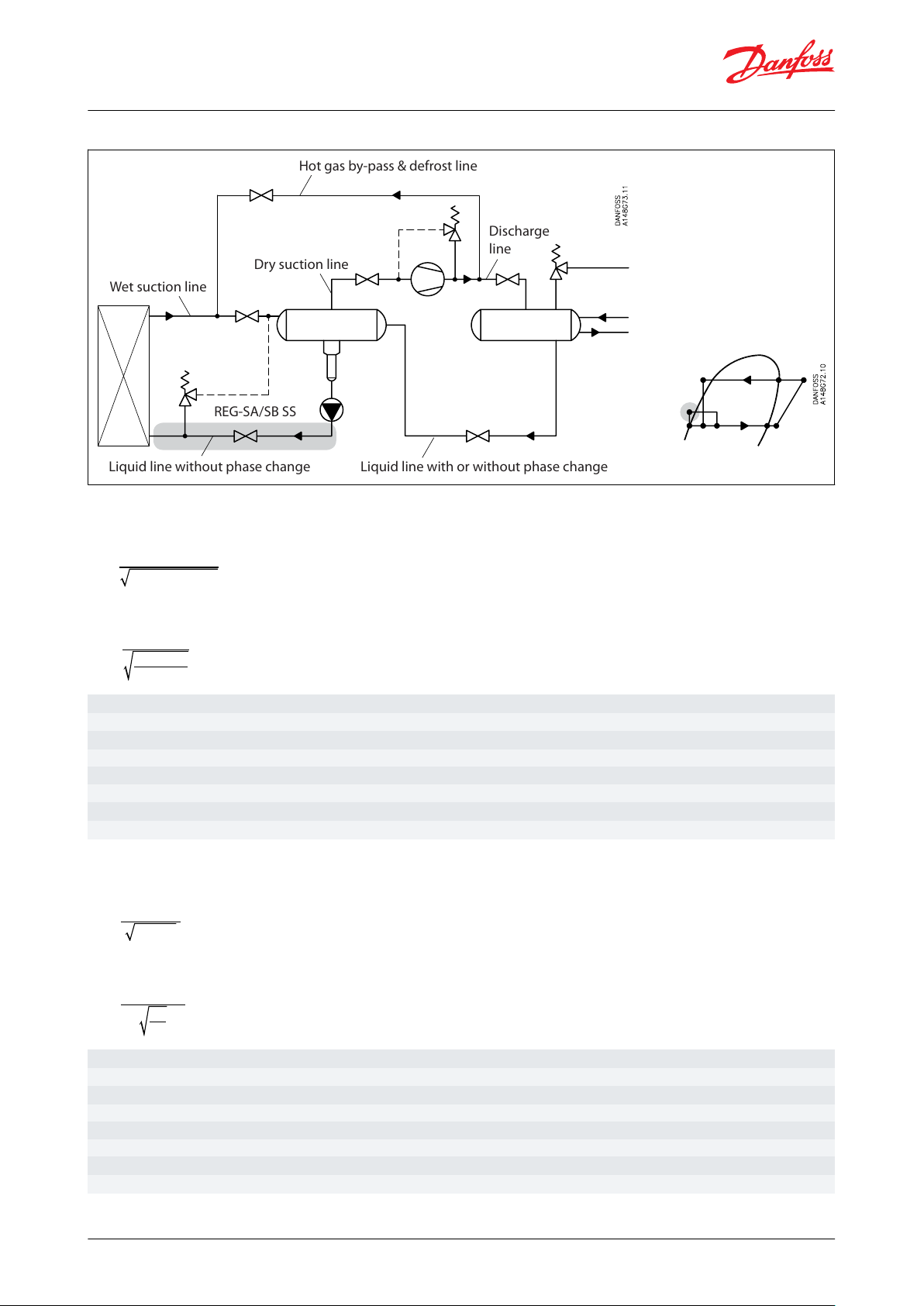
Liquid line without phase change Liquid line with or without phase change
REG-SA/SB SS
Wet suction line
Dry suction line
Hot gas by-pass & defrost line
Discharge
line
kv[m
3
/h]
Quantity [m
3
/h] of water owing through a valve at a pressure loss of 1 bar (according to VDE/VDI Norm 2173).
P
1
[bar]
Pressure before the valve (upstream).
P
2
[bar]
Pressure after the valve (downstream).
Δp
[bar]
Actual pressure loss across the valve (P1–P2).
G
[kg/h]
Mass
ow through the valve.
V
[m
3
/h]
Volume ow through the valve.
ρ
[kg/m
3
]
Density of the refrigerant before the valve.
C
A
Calculation factor (See
Figure 10: Calculation factor CA).
C
v
[US gal/min]
Quantity [US gal/min] of water
owing through a valve at a pressure loss of 1 psi.
P
1
[psi]
Pressure before the valve (upstream).
P
2
[psi]
Pressure after the valve (downstream).
Δp
[psi]
Actual pressure loss across the valve (P1–P2).
G
[lb/min]
Mass
ow through the valve.
V
[US gal/min]
Volume
ow through the valve.
ρ
[lb/ft
3
]
Density of the refrigerant before the valve.
C
A
Calculation factor (See
Figure 10: Calculation factor CA).
Hand operated regulating valve, type REG-SA SS and REG-SB SS
Figure 5: Location of valve in system (marked with grey)
SI-units
Mass ow:
kv=
G
ρ × 1000 × Δp
Volume ow:
∨
=
k
v
1000 × Δp
ρ
Imperial units
Mass ow:
0.95 × G
Cv=
ρ × Δp
Volume ow:
0.127 × ∨
=
C
v
Δp
ρ
= G×CA[m3/h]
[m3/h]
= 31.6 × G × CA[USgal/ min . ]
[USgal/ min . ]
© Danfoss | Climate Solutions | 2021.02 AI234986440271en-000601 | 7

B
A
0
0
0% 25% 50% 75% 10 0%
Turn of spindle
Opening
Kv(Cv)
0.5
1
1.5
2
2.5
3
3.5
4
4.5
5
1 2 3 4 5 6 7 8 9
(5.80)
(5.22)
(4.64)
(4.06)
(3.48)
(2.90)
(2.32)
(1.74)
(1.16)
(0.58)
Flow coefficient
B
A
0% 2 5% 50% 75% 100%
Turn of spindle
Opening
Kv(Cv)
Flow coefficient
0
2
4
6
8
10
12
14
16
18
20
0 1 2 3 4 5 6 7 8 9 10 11 12
(23.20)
(20.88)
(18.56)
(16.24)
(13.92)
(11.60)
(9.28)
(6.96)
(4.64)
(2.32)
Hand operated regulating valve, type REG-SA SS and REG-SB SS
Figure 6: REG-SA SS 15-20 and REG-SB SS 15-20
Figure 7: REG-SA SS 25-40 and REG-SB SS 25-40
Liquid R 717, density: 670 kg/m3 [42 lb/ft3]
© Danfoss | Climate Solutions | 2021.02 AI234986440271en-000601 | 8

0
1
2
3
4
5
6
7
8
9
0%
25%
50%
75%
100%
Turn of spindle
A
B
Turn of spindle
Opening
kg/h
(lb/min)
8000
(294)
4000
(147)
R717
∆P = 0.5 bar (7 psi)
∆P = 1 bar (14 psi)
∆P = 1.5 bar (22 psi)
∆P = 2 bar (29 psi)
kg/h
(lb/min)
30000
(1103)
20000
(735)
B
A
10000
(368)
∆P = 0.5 bar (7 psi)
∆P = 1 bar (14 psi)
∆P = 1.5 bar (22 psi)
∆P = 2 bar (29 psi)
0
1
2
3
4
5
6
7
8
9
10
11
12
Turn of spindle
R717
Opening
0%
25%
50%
75%
100%
Hand operated regulating valve, type REG-SA SS and REG-SB SS
Figure 8: REG-SA SS 15-20 and REG-SB SS 15-20
Figure 9: REG-SA SS 25-40 and REG-SB SS 25-40
© Danfoss | Climate Solutions | 2021.02 AI234986440271en-000601 | 9

Hand operated regulating valve, type REG-SA SS and REG-SB SS
Figure 10: Calculation factor C
NOTE:
A
For choice of valve size and connection see "Connections".
Computation and selection Example 1.
Refrigerant: R 717
Refrigerant ow: 2200 kg/h
Pressure drop: Δp = 0.5 bar
The above mentioned example is illustrated on the following ow rate diagram and shows that REG-SB SS 15 and 20
with cone B can be used. The main rule is that nominal regulation range should be below 85% opening degree. If
the arrowline is crossing 2 cone curves, the smaller cone should be selected if opening degree < 85%.
The example is only correct if the density of the refrigerant is approx. 670 (kg/m3), and there must be no build-up of
ash gas in the valve.
© Danfoss | Climate Solutions | 2021.02 AI234986440271en-000601 | 10

2200
(81)
0
1
2
3
4
5
6
7
8
9
0%
25%
50%
75%
100%
Turn of spindle
A
B
Turn of spindle
Opening
kg/h
(lb/min)
8000
(294)
4000
(147)
R717
∆P = 0.5 bar (7 psi)
∆P = 1 bar (14 psi)
∆P = 1.5 bar (22 psi)
∆P = 2 bar (29 psi)
REG-SA SS 15-20 and REG-SB SS 15-20
Hand operated regulating valve, type REG-SA SS and REG-SB SS
Figure 11: Flow rate diagram
Computation and selection Example 2.
Brine, density ρ: 1150 [kg/m3]
Brine ow G: 2,700 [kg/h]
Pressure drop Δp: 0.5 [bar]
In this example it is not possible to use the selection diagrams (Figure 8: REG-SA SS 15-20 and REG-SB SS 15-20 and
Figure 9: REG-SA SS 25-40 and REG-SB SS 25-40) as the refrigerant in question is not included.
Use the curves of the kv-values instead (Figure 6: REG-SA SS 15-20 and REG-SB SS 15-20 and Figure 7: REG-SA SS
25-40 and REG-SB SS 25-40) and calculate the required kv by means of the formulas in the "Introduction" passage at
the beginning of this chapter. Alternatively calculate the kv-values by means of the calculation factor CA (Figure 12:
Flow rate diagramCalculation factor CA) and the ow rate diagram (in this example: Figure 13: Flow rate diagram) as
per the following calculation example.
Calculation example:
Required kv-value
CA = 0.00132 (from Figure 13: Flow rate diagram)
kv = CA × G
kv = 0.00132 × 2,700 [kg/h]
= 3.56 [m3/h]
© Danfoss | Climate Solutions | 2021.02 AI234986440271en-000601 | 11

Density kg/m3
[lb/ft]
B
A
0
0
0% 25% 50% 75% 100%
Turn of spindle
Opening
Kv(Cv)
0.5
1
1.5
2
2.5
3
3.5
4
4.5
5
1 2 3 4 5 6 7 8 9
(5.80)
(5.22)
(4.64)
(4.06)
(3.48)
(2.90)
(2.32)
(1.74)
(1.16)
(0.58)
3.56 m3/h
(from
calculation
above)
Hand operated regulating valve, type REG-SA SS and REG-SB SS
Figure 12: Calculation factor C
Figure 13: Flow rate diagram
A
REG-SB SS 15 and REG-SB SS 20 with cone B can be used.
© Danfoss | Climate Solutions | 2021.02 AI234986440271en-000601 | 12

Danfoss
M148B0010_1
17
11
18
8
10
9
7
12
2
13
3A
4
1
21
5
No.
Part
Material
EN
ISO
ASTM
1
Housing
Stainless steel
GX5CrNi19-10
EN10213-4
AISI 304
2
Bonnet, Flange
Stainless steel
X5CrNi18-10
EN10088
AISI 304
3A
Bonnet, Insert
Stainless steel
X8CrNiS18-9
DIN 17440
AISI 303
4
Spindle
Stainless steel
X8CrNiS 18-9
DIN 17440
Type 17, 683/13
AISI 303
5
Cone
Steel7Packing washer
Aluminium
8
Packing gland
Stainless Steel
X8CrNiS 18-9, 10088
Type 17, 683/13
AISI 303
9
O-ring
Chloroprene (Neoprene)
10
Spring loaded Teon ring
PTFE11O-ring
Chloroprene (Neoprene)
12
Bolts
Stainless steel
A2-70
A2-70
Type 308
13
Gasket
Fiber, non asbestos
14
Bottom insert
Steel17Seal cap
Aluminium
18
Gasket f. seal cap
Nylon19Locking nut
Steel20Screw
Steel21Disk spring
Steel
Hand operated regulating valve, type REG-SA SS and REG-SB SS
Material specication
Figure 14: REG-SA SS and REG-SB SS 15 - 40
Table 4: Material and parts
© Danfoss | Climate Solutions | 2021.02 AI234986440271en-000601 | 13

ØD
G
G
C
H
Valve sizeCG∅DH
Weight
REG-SA SS/SB SS 15-20
REG-SA SS/SB SS (½-3/4)
mm
in.
182
7.17451.77381.50602.36
1.4 kg
3.1 lb
REG-SA SS/SB SS 25-40
REG-SA SS/SB SS (1-1½)
mm
in.
237
9.33552.17501.97702.76
2.4 kg
5.3 lb
G
B
H
E
C
D
Hand operated regulating valve, type REG-SA SS and REG-SB SS
Dimensions and weights
REG-SA SS and REG-SB SS 15 - 40 in angleway version
Figure 15: REG-SA SS and REG-SB SS 15 - 40
Table 5: Valve size and weight
NOTE:
Specied weights are approximate values only.
REG-SA SS and REG-SB SS 10 - 65 in straightway version
Figure 16: REG-SA SS and REG-SB SS 15 - 40
© Danfoss | Climate Solutions | 2021.02 AI234986440271en-000601 | 14

Valve sizeCBEG∅DH
Weight
REG-SA SS/SB SS 15-20
REG-SA SS/SB SS (½-3/4)
mm
in.
145
5.71
155
6.10200.79
120
4.72381.50602.36
2.0 kg
4.4 lb
REG-SA SS/SB SS 25-40
REG-SA SS/SB SS (1-1½)
mm
in.
200
7.87
215
8.46261.02
155
6.10501.97702.76
3.0 kg
6.6 lb
Hand operated regulating valve, type REG-SA SS and REG-SB SS
Table 6: Valve size and weight
NOTE:
Specied weights are approximate values only.
© Danfoss | Climate Solutions | 2021.02 AI234986440271en-000601 | 15

Valve type
REG SA SS
REG-SB SS
Regulating Valves
Nominal size in mm
(Valve size measured on
the connection diameter)
15
20
25
32
40
DN 15
DN 20
DN 25
DN 32
DN 40
Available connection types
D
x
x
x
x
x
A
x
x
x
x
x
Connections
D
A
Butt-weld connection: DIN EN 10220
Butt-weld connection: ANSI B 36.19M
Valve housing
ANG
Angle ow
STR
Straight ow
Cone A
Size:
DN 15
DN 20
DN 25
DN 32
DN 40
Flow area [mm2]
36.5
36.5
178
178
178
Cone B
Size:
DN 15
DN 20
DN 25
DN 32
DN 40
Flow area [mm2]
115
115
531
531
531
Size
Type
Code no.
mm
in.
Angleway
- REG-SA SS with cone type A
15
½
REG-SA SS 15 D ANG
148B529720¾
REG-SA SS 20 D ANG
148B5385251
REG-SA SS 25 D ANG
148B5494
32
1 ¼
REG-SA SS 32 D ANG
148B5589
40
1 ½
REG-SA SS 40 D ANG
148B5674
Size
Type
Code no.
mm
in.
Straightway
- REG-SA SS with cone type A
15
½
REG-SA SS 15 D STR
148B529820¾
REG-SA SS 20 D STR
148B5386251
REG-SA SS 25 D STR
148B5495
32
1 ¼
REG-SA SS 32 D STR
148B5590
40
1 ½
REG-SA SS 40 D STR
148B5675
Hand operated regulating valve, type REG-SA SS and REG-SB SS
Ordering
How to order
The table below is used to indentify the valve required.
Please note that the type codes only serve to identify the valves, some of which may not form part of the standard
product range. For further information please contact your local Danfoss Sales Company.
Table 7: Type codes
Complete REG-SA SS (Cone type A)
Example:
REG-SA SS (Cone B) 15 DIN angleway = 148B5387
Table 8: Butt-weld DIN (EN 10220)
Table 9: Butt-weld DIN (EN 10220)
© Danfoss | Climate Solutions | 2021.02 AI234986440271en-000601 | 16

Size
Type
Code no.
mm
in.
Angleway - REG-SA SS with cone type A
15
½
REG-SA SS 15 A40 ANG
148B6482251
REG-SA SS 25 A40 ANG
148B6483
32
1 ¼
REG-SA SS 32 A40 ANG
148B6484
Size
Type
Code no.
mm
in.
Straightway - REG-SA SS with cone type A
15
½
REG-SA SS 15 A40 STR
148B5299251
REG-SA SS 25 A40 STR
148B6485
32
1 ¼
REG-SA SS 32 A40 STR
148B6486
Size
Type
Code no.
mm
in.
Angleway - REG-SB SS with cone type B
15
½
REG-SB SS 15 D ANG
148B538720¾
REG-SB SS 20 D ANG
148B5389251
REG-SB SS 25 D ANG
148B5496
32
1 ¼
REG-SB SS 32 D ANG
148B5591
40
1 ½
REG-SB SS 40 D ANG
148B5676
Size
Type
Code no.
mm
in.
Straightway - REG-SB SS with cone type B
15
½
REG-SB SS 15 D STR
148B538820¾
REG-SB SS 20 D STR
148B5390251
REG-SB SS 25 D STR
148B5497
32
1 ¼
REG-SB SS 32 D STR
148B5592
40
1 ½
REG-SB SS 40 D STR
148B5677
Size
Type
Code no.
mm
in.
Angleway - REG-SB SS with cone type B
20
¾
REG-SB SS 20 A40 ANG
148B6487
40
1 ½
REG-SB SS 40 A40 ANG
148B5686
Size
Type
Code no.
mm
in.
Straightway - REG-SA SS with cone type A
20
¾
REG-SB SS 20 A40 STR
148B6488251
REG-SB SS 25 A40 STR
148B6479
40
1 ½
REG-SB SS 40 A40 STR
148B5685
Hand operated regulating valve, type REG-SA SS and REG-SB SS
Table 10: Butt-weld ANSI (B 36.19M SCHEDULE 40)
Table 11: Butt-weld ANSI (B 36.19M SCHEDULE 40)
D = Butt-weld DIN
A = Butt-weld ANSI
ANG = Angleway
STR = Straightway
Complete REG-SB SS (Cone type B)
Table 12: Butt-weld DIN (EN 10220)
Table 13: Butt-weld DIN (EN 10220)
Table 14: Butt-weld ANSI (B 36.19M SCHEDULE 40)
Table 15: Butt-weld ANSI (B 36.19M SCHEDULE 40)
© Danfoss | Climate Solutions | 2021.02 AI234986440271en-000601 | 17

Size
O-ring kit for
mm
in.
R717
Heat pump
R1270
Propylene
10⅜148B6084
148B608515½
148B6070
148B6077
20¾25
1
148B6071
148B6078
321¼40
1½
Hand operated regulating valve, type REG-SA SS and REG-SB SS
D = Butt-weld DIN
A = Butt-weld ANSI
ANG = Angleway
STR = Straightway
Replacement kit
Replacement kit (O-ring replacement) for R717 Ammonia Heat Pump
Table 16: O-ring kit
(1)
and Propylene applications (including ID tag)
1
Replacement kits for R717 Ammonia Heat Pump is applicable for continuous operating temperature between +100 °C - 150 °C (212 °F - 302 °F)
© Danfoss | Climate Solutions | 2021.02 AI234986440271en-000601 | 18

REG-SA/SB SS valves are approved according to the European standard specied in the Pressure Equipment Directive and are CE marked.
REG-SA SS and REG-SB SS valves
Nominal bore
DN = < 25 mm (1 in.)
DN32-40 mm (1¼ - 1½ in.)
Classied for
Fluid group I
Catagory
Article 3, paragraph 3
II
File name
Document type
Document topic
Approval authority
03709-F0 BV
Marine - Safety Certicate
-BV033F0685.AK
EU Declaration
EMCD/PED
Danfoss
033F0691.AE
Manufacturers Declaration
RoHS
Danfoss
Hand operated regulating valve, type REG-SA SS and REG-SB SS
Certicates, declarations, and approvals
The list contains all certicates, declarations, and approvals for this product type. Individual code number may have
some or all of these approvals, and certain local approvals may not appear on the list.
Some approvals may change over time. You can check the most current status at danfoss.com or contact your local
Danfoss representative if you have any questions.
Table 17: Pressure Equipment Directive (PED)
Table 18: Valves specications
Table 19: Certicates and declarations
© Danfoss | Climate Solutions | 2021.02 AI234986440271en-000601 | 19

Online support
Danfoss oers a wide range of support along with our products, including digital product information, software,
mobile apps, and expert guidance. See the possibilities below.
The Danfoss Product Store
The Danfoss Product Store is your one-stop shop for everything product related—no matter where
you are in the world or what area of the cooling industry you work in. Get quick access to essential
information like product specs, code numbers, technical documentation, certications, accessories,
and more.
Start browsing at store.danfoss.com.
Find technical documentation
Find the technical documentation you need to get your project up and running. Get direct access to
our ocial collection of data sheets, certicates and declarations, manuals and guides, 3D models
and drawings, case stories, brochures, and much more.
Start searching now at www.danfoss.com/en/service-and-support/documentation.
Danfoss Learning
Danfoss Learning is a free online learning platform. It features courses and materials specically
designed to help engineers, installers, service technicians, and wholesalers better understand the
products, applications, industry topics, and trends that will help you do your job better.
Create your Danfoss Learning account for free at www.danfoss.com/en/service-and-support/learning.
Get local information and support
Local Danfoss websites are the main sources for help and information about our company and
products. Find product availability, get the latest regional news, or connect with a nearby expert—all
in your own language.
Find your local Danfoss website here: www.danfoss.com/en/choose-region.
Spare Parts
Get access to the Danfoss spare parts and service kit catalog right from your smartphone. The app
contains a wide range of components for air conditioning and refrigeration applications, such as
valves, strainers, pressure switches, and sensors.
Download the Spare Parts app for free at www.danfoss.com/en/service-and-support/downloads.
Coolselector®2 - nd the best components for you HVAC/R system
Coolselector®2 makes it easy for engineers, consultants, and designers to nd and order the best
components for refrigeration and air conditioning systems. Run calculations based on your operating
conditions and then choose the best setup for your system design.
Download Coolselector®2 for free at coolselector.danfoss.com.
Danfoss can accept no responsibility for possible errors in catalogues, brochures and other printed material. Danfoss reserves the right to alter its
products without notice. This also applies to products already on order provided that such alterations can be made without subsequential
changes being necessary in specications already agreed. All trademarks in this material are property of the respective companies. Danfoss and
the Danfoss logotype are trademarks of Danfoss A/S. All rights reserved.
© Danfoss | Climate Solutions | 2021.02 AI234986440271en-000601 | 20
 Loading...