

Installation guide
Regulating valves in stainless steel/HL Packing Gland
REG-SA SS, REG-SB SS DN15-40
Installation
148R9652
1
2
Max. Nm
Nm máx.
最大Nm
Maks. (Nm)
Макс.
момент
затяжки, Нм
DN 15-20 21 15
DN 25-40 44 32
Max. LB-feet
lb-ft máx.
Max. Lb-piedi
最大LB-英尺
Maks. (lbf x ft)
Макс.момент
затяжки,
фунт/фут
148R9652
3
5 6
© Danfoss | DCS (ms) | 2021.04
4
AN376339413133en-000101 | 1
Maintenance
D
Danfoss
M148B0031_1
7 8
Nm LB-feet
DN 10 30 22
DN 15-20 50 37
DN 25-40 75 55
9 10 11
Danfoss
M148B0026_1
Ensure tight screw connection
A
12
13
Danfoss
M148G0018_1
© Danfoss | DCS (ms) | 2021.04
AN376339413133en-000101 | 2

ENGLISH
Installation
Refrigerants
Applicable to HCFC, HFC, R717 (Ammonia),
R744 (CO2), Propane, Butane, Iso-Butane
and Ethane.
The valve is only recommended for use
in closed circuits. For further information
please contact Danfoss.
Temperature range
-60 °C/+150 °C (-76 °F/+302 °F)
Max. working pressure
The valves are designed for a max. working
pressure of 52 bar (754 psig).
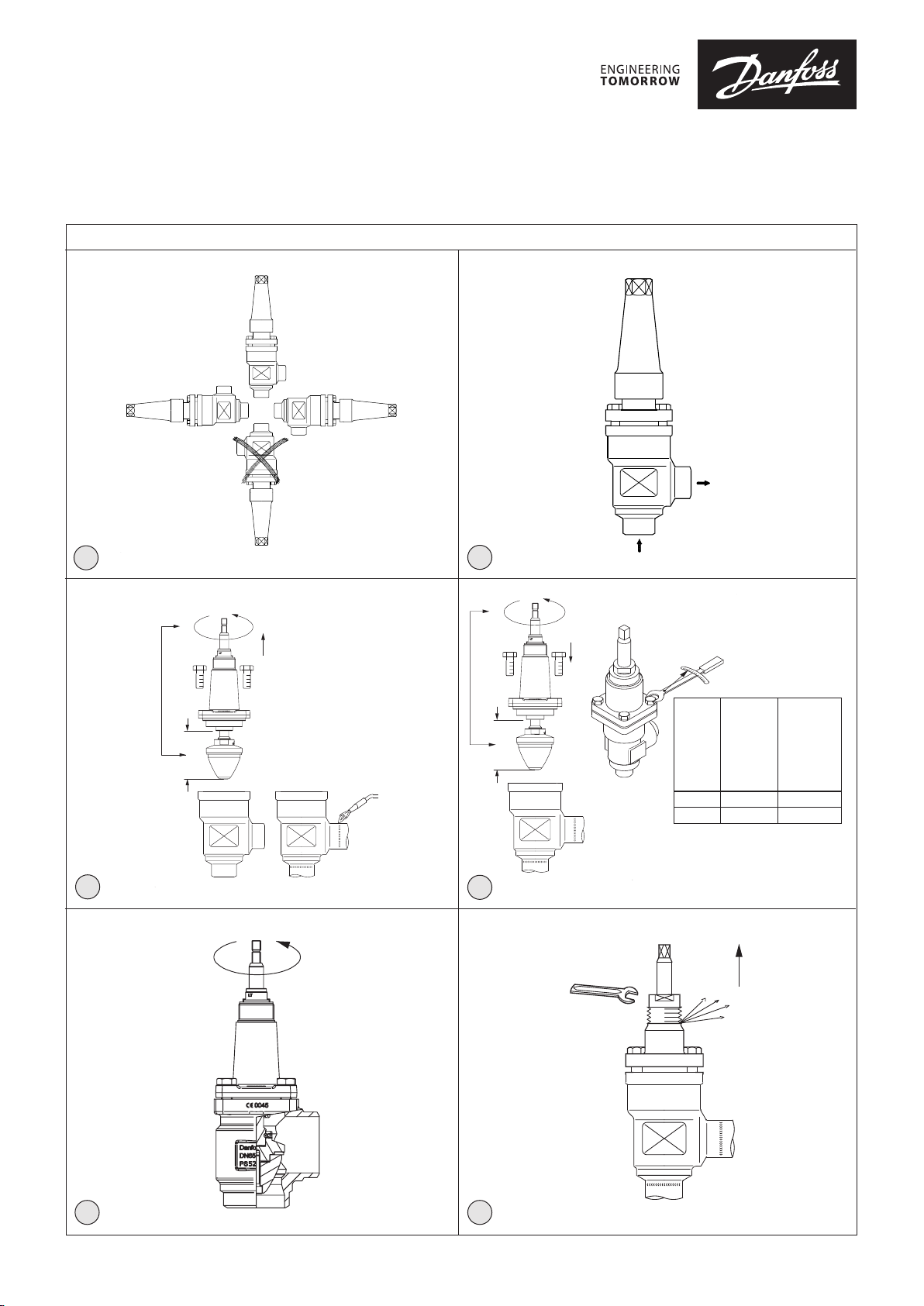
Installation
The valve must be installed with the
spindle vertically upwards or in horizontal
position (fig. 1). Valves should be opened
by hand. The valve is designed to withstand
a high internal pressure. However, the
piping system should be designed to avoid
liquid traps and reduce the risk of hydraulic
pressure caused by thermal expansion.
Please ensure that the valve is protected
from pressure transients like “liquid
hammer” in the system.
Recommended flow direction
Direct the flow towards the cone as
indicated by the arrow placed on the valve
housing (fig. 2). The force used to open and
close the valve must not exceed the force
of an ordinary handwheel.
Welding
Remove the bonnet before welding (fig. 3)
to prevent damage to the O-rings in the
packing gland and between the valve body
and bonnet, as well as the teflon gasket in
the valve seat. Be careful not to damage
the teflon cone ring and make sure the
complete bonnet is protected from dirt
and water while removed.
Removing the bonnet can be omitted
provided that: The temperature in the
area between the valve body and bonnet
during welding does not exceed
+150 °C/+302 °F. This temperature depends
on the welding method as well as on
any cooling of the valve body during the
welding itself. (Cooling can be ensured
by, for example, wrapping a wet cloth
around the valve body.) Make sure that no
dirt, welding debris etc. get into the valve
during the welding procedure.
Only materials and welding methods,
compatible with the valve housing
material, must be applied to the valve
housing. The valve housing must be
free from stresses (external loads) after
installation.
Clean the valve internally to remove
welding debris at completion of welding
and before the valve is reassembled. Avoid
welding debris and dirt in the threads of
the housing and the bonnet.
Do NOT remove or service the dark colored
grease between the spindle thread and
the bonnet. In case the grease has been
contaminated with dirt, debris, particles
or water the complete top part must be
replaced.
Do not mount REG valves in systems where
the outlet side of the valve is open to
atmosphere. The outlet side of the valve
must always be connected to the system
or properly capped off, for example with a
welded-on end plate.
Assembly
Remove welding debris and any dirt from
pipes and valve body before assembly.
Check that the cone has been fully screwed
back towards the bonnet before it is
repositioned in the valve body
(REG-SA/SB SS DN 15-40) (fig. 4).
Tightening
Tighten the bonnet with a torque wrench,
to the values listed in the table (fig. 4).
Colours and identification
The REG-SA/SB SS valves are painted
with a red primer in the factory. Precise
identification of the valve is made via the
yellow ID ring at the top of the bonnet, as
well as by the stamping on the valve body.
The external surface of the valve housing
must be protected against corrosion
with a suitable protective coating after
installation and assembly.
Protection of the ID ring when repainting
the valve is recommended.
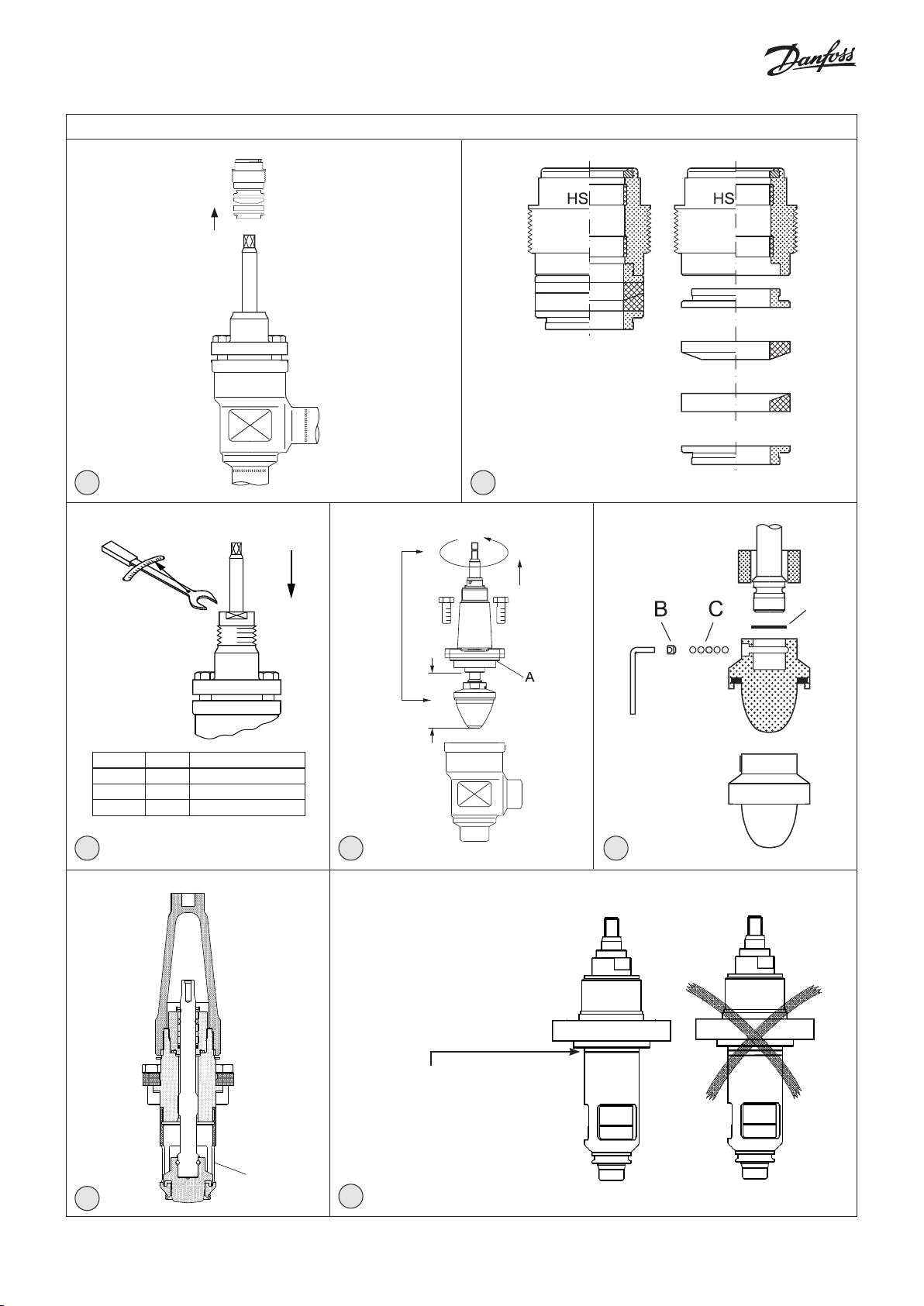
Maintenance
Packing gland
When performing service and
maintenance, replace the complete
packing gland only, which is available as a
spare part. As a general rule, the packing
gland must not be removed if there is
internal pressure in the valve. However, if
the following precautionary measures are
taken, the packing gland can be removed
with the valve still under pressure:
Backseating (fig. 5)
To backseat the valve, turn the spindle
counter-clockwise until the valve is fully
open.
Pressure equalization (fig. 6)
In some cases, pressure forms behind the
packing gland. Hence a handwheel or
similar should be fastened on top of the
spindle while the pressure is equalized.
The pressure can be equalized by slowly
screwing out the gland.
Removal of packing gland (fig. 7)
The packing gland can now be removed.
Fitting a replacement packing gland
(Fig. 8)
Great care should be taken when fitting a
new packing gland and damage to Teflon
gaskets must be avoided.
During fitting, the individual components
in the packing gland should be placed in
order and positioned as shown (Fig. 8).
Dismantling the valve
Do not remove the bonnet while the valve
is still under pressure.
- Check that the O-ring (fig. 10, pos. A) has
not been damaged.
- Check that the spindle is free of scratches
and impact marks.
- If the teflon cone ring has been
damaged, the whole cone assembly
must be replaced.
- DN 15-40: Unscrew the adapter (fig. 12,
pos. A) to be able to change the cone.
Replacement of the cone (fig. 11)
Unscrew the cone screw (pos. B) with an
Allen key. (An Allen key is included in the
Danfoss Industrial Refrigeration gasket set).
REG-SA/SB SS 15-40 ...................... 2.0 mm A/F
Remove the balls (pos. C).
Number of balls in fig. 11, pos. C:
REG-SA/SB SS 15-20 ................................ 10 pcs.
REG-SA/SB SS 25-40 ................................ 14 pcs.
The cone can now be removed. Place the
new cone on the spindle and remember to
place the disk spring (pos. D) between the
spindle and the cone. Compress the disk
spring and replace the balls (pos. C).
Refit the cone screw in again using Loctite
No. 648. to ensure that the screw is
properly fastened.
Do NOT remove or service the dark colored
grease between the spindle thread and
the bonnet. In case the grease has been
contaminated with dirt, debris, particles
or water the complete top part must be
replaced.
Assembly
Remove any dirt from the body before the
valve is assembled. Check that the cone
has been screwed back towards the bonnet
before it is replaced in the valve body (fig. 4).
Note:
For REG-SA/SB SS sizes DN 15-40 it is
important to ensure that the lower
and upper part of the insert is tightly
screwed together (fig. 13) and that this
screw connection is kept tight during
repositioning of the cone in the housing.
Tightening
Tighten the bonnet with a torque wrench,
to the values indicated in the table (fig. 4).
Tighten the packing gland with a torque
wrench, to the values indicated in the table
(fig. 9).
Use only original Danfoss parts, including
packing glands, O-rings and gaskets for
replacement. Materials of new parts are
certified for the relevant refrigerant.
In cases of doubt, please contact your local
Danfoss sales office.
© Danfoss | DCS (ms) | 2021.04
AN376339413133en-000101 | 3

Danf
oss can accept no responsibility for possible errors in catalogues, brochures and other printed material. Danfoss reserves the right to alter its products without notice. This also applies to products
already on order pro
All trademarks in this material are property of the respec
vided that such alterations can be made without subsequential changes being necessary eady agreed.
tive companies. Danfoss and the Danfoss logotype are trademarks of Danfoss A/S. All rights reserved.
© Danfoss | DCS (ms) | 2021.04
AN376339413133en-000101 | 4
 Loading...