

Data Sheet
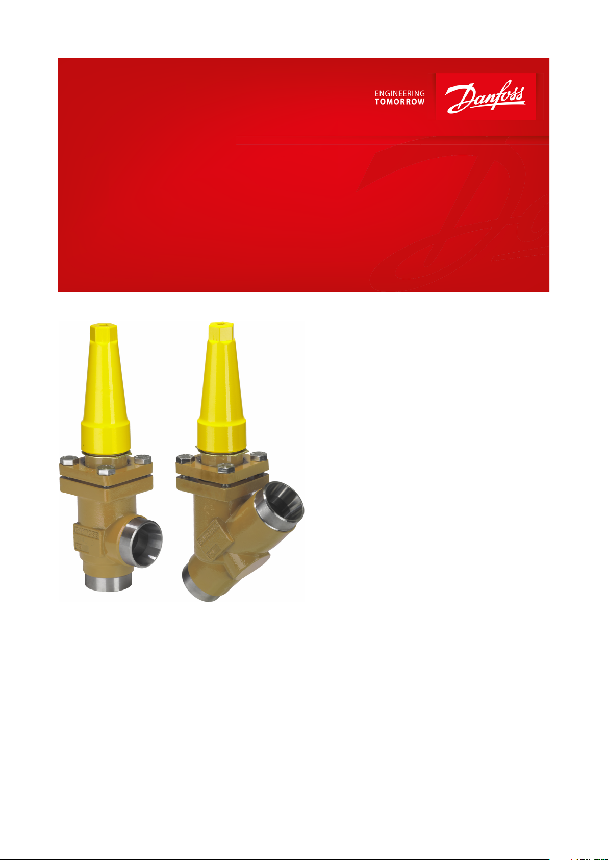
Hand operated regulating valve
Type REG-SA and REG-SB 65
Designed for regulation purposes in liquid and expansion lines, suitable for MWP up to 65 bar
REG-SA and REG-SB are angleway and
straightway hand regulating valves, which act
as normal stop valves in closed position.
The valves are available in two dierent
versions – REG-SA and REG-SB designed for
regulation purposes in liquid and expansion
lines.
The valves are designed to meet the strict
quality requirements on refrigerating/heat
pump installations specied by the
international classication societies and are
carefully designed to present favourable ow
conditions and accurate linear characteristics.
REG-SA and REG-SB are equipped with vented
cap and internal backseating enables
replacement of the spindle seal whilst the valve
is active, i.e. under pressure.
AI367729279610en-000101
Hand operated regulating valve, type REG-SA and REG-SB 65
Features
• Modular Concept:
◦ Each valve housing is available with DIN and ANSI butt weld connection and in several dierent sizes.
◦ Possible to convert REG-SA or REG-SB to any other product in the FlexlineTM SVL family (shut-o valve, check &
stop valve, check valve or strainer) just by replacing the complete top part.
• Fast and easy valve overhaul service. It is easy to replace the top part and no welding is needed.
• Designed to ensure perfect regulation
• Internal backseating enables replacement of the spindle seal whilst the valve is active, i.e. under pressure.
• Easy to disassemble for inspection and possible repair.
• Acts as a normal stop valve in closed position.
• Housing and bonnet material is low temperature steel according to requirements of the Pressure Equipment
Directive and other international classication authorities.
• Exact capacity and setting of the valve can be calculated for all refrigerants by means of Coolselector™.
• Classication: DNV, CRN, BV, EAC etc. To get an updated list of certication on the products please contact your
local Danfoss Sales Company.
• Equipped with 42CrMo5 bolts to withstand high pressure.
• Service kits with replacement O-rings for R717 Heat Pump and R1270 Propylene include separate ID-ring for ID of
application
Media
Refrigerants
Applicable to HCFC, HFC, R717 (Ammonia), R744 (CO₂) and ammable refrigerants.
For further information refer to the product instruction for REG-SA and REG-SB.
New refrigerants
Danfoss products are continually evaluated for use with new refrigerants depending on market requirements.
When a refrigerant is approved for use by Danfoss, it is added to the relevant portfolio, and the R number of the
refrigerant (e.g. R513A) will be added to the technical data of the code number. Therefore, products for specic
refrigerants are best checked at store.danfoss.com/en/, or by contacting your local Danfoss representative.
© Danfoss | Climate Solutions | 2021.04 AI367729279610en-000101 | 2
Description
Values
Temperature range
-60 °C /+150 °C (-76 °F /+302 °F).
Max. working pressure
65 bar (943 psig).
OD
T
Size
ODTOD
T
kv-angle
kv-straight
Cv-angle
Cv-straight
mm
in.mmmm
in.
in.
m3/h
m3/h
USgal/min
USgal/min
6¼13.5
2.3
0.531
0.091
2.9
2.0
3.4
2.410⅜
17.2
2.3
0.677
0.091
4.5
3.2
5.2
3.615½
21.3
2.3
0.839
0.091
7.0
4.9
8.1
5.720¾
26.9
2.3
1.059
0.091
14.6
10.2
16.9
11.8251
33.7
2.6
1.327
0.103
24.8
17.4
28.8
20.2321¼
42.4
2.6
1.669
0.102
42.6
29.8
49.4
34.6401½
48.3
2.6
1.902
0.103
45.2
31.6
52.4
36.7502
60.3
2.9
2.37
0.1180659376652½
76.1
2.930.11
12097140
113803
88.9
3.2
3.50
0.13
182
152
211
176
1004114.3
3.6
4.50
0.14
313
278
363
323
1255139.7
4.0
5.50
0.16
514
470
596
545
1506168.3
4.5
6.63
0.18
785
597
911
693
2008219.1
6.3
8.63
0.25
1168
1024
1355
1188
OD
T
Size
ODTOD
T
k
v
-angle
k
v
-straight
C
v
-angle
C
v
-straight
mm
in.mmmm
in.
in.
m
3
/h
m
3
/h
USgal/min
USgal/min
6¼13.5
3.0
0.531
0.118
2.9
2.03
3.4
2.410⅜
17.2
3.2
0.677
0.126
4.5
3.15
5.2
3.615½
21.3
3.7
0.839
0.146
7.0
4.9
8.1
5.7
Hand operated regulating valve, type REG-SA and REG-SB 65
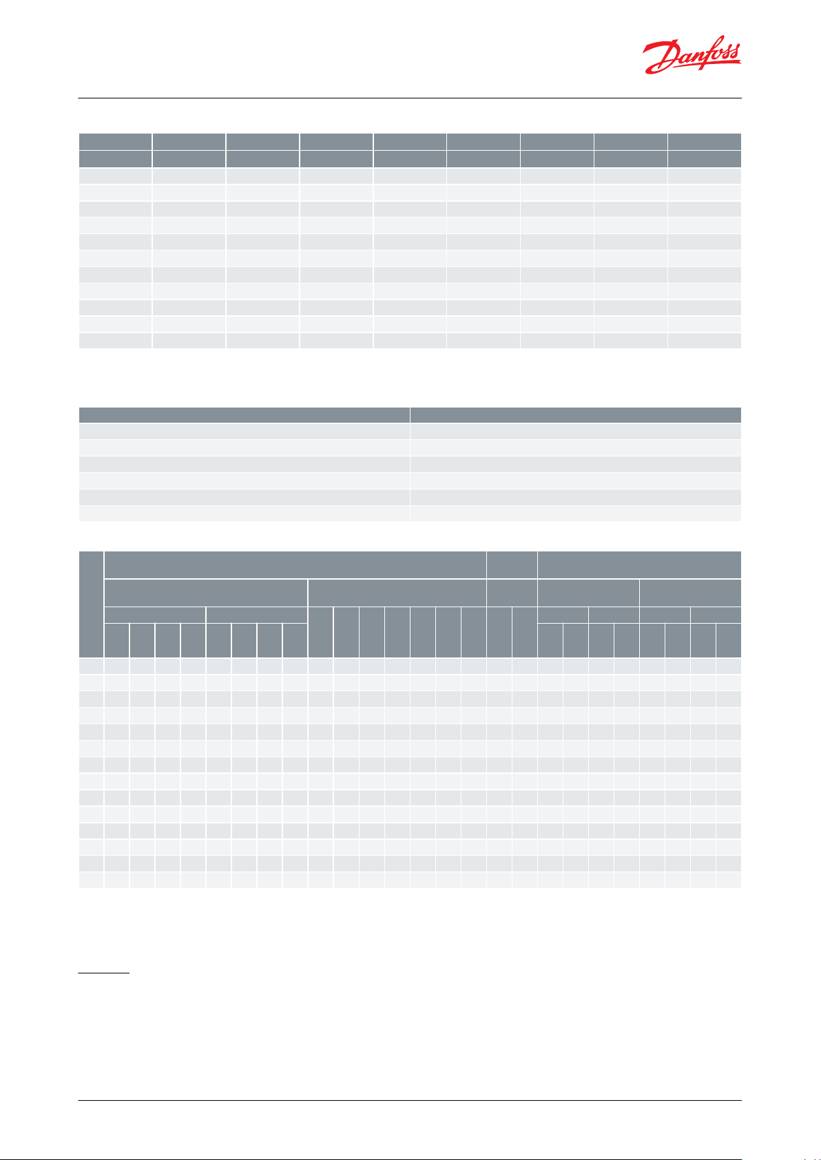
Product specication
Pressure and temperature data
Table 1: Temperature and pressure
With O-ring replaced for valves up to DN40 (Service kit):
• Heat pump conguration: R717 - 65 bar (943 psi) @ +100 °C to +150 °C (+212 °F to +302 °F) continuous.
• Propylene conguration: R1270 - 65 bar (943 psi) @ -60 °C to 150 °C (-76 °F to 302 °F).
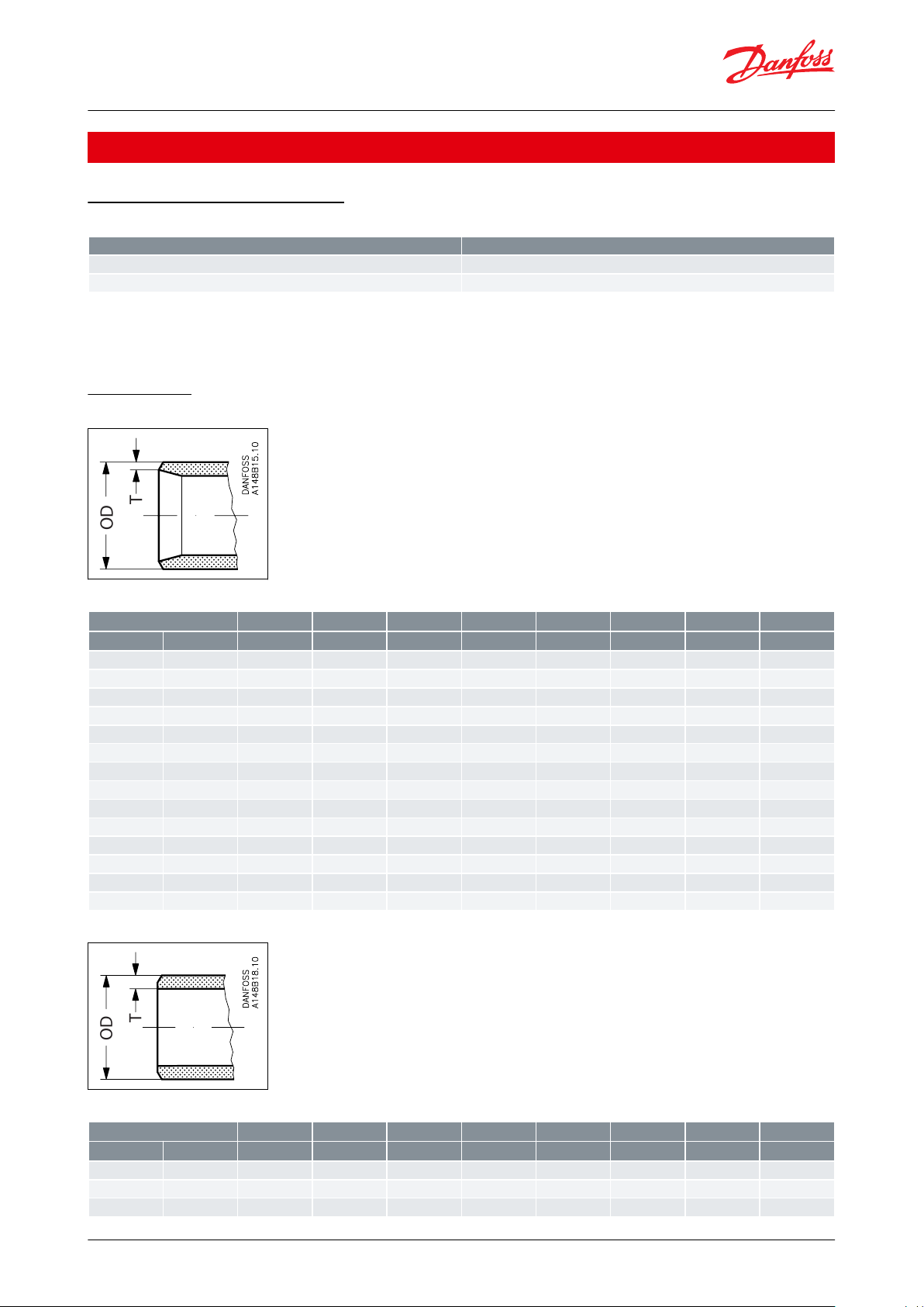
Connections
Figure 1: DIN
Table 2: Butt-weld DIN (EN 10220)
Figure 2: ANSI
Table 3: Butt-weld ANSI (B 36.10 Schedule 80)
© Danfoss | Climate Solutions | 2021.04 AI367729279610en-000101 | 3
Size
ODTOD
T
kv-angle
kv-straight
Cv-angle
Cv-straight
mm
in.mmmm
in.
in.
m3/h
m3/h
USgal/min
USgal/min
20¾26.9
4.0
1.059
0.158
14.6
10.2
16.9
11.8251
33.7
4.6
1.327
0.181
24.8
17.4
28.8
20.2321¼
42.4
4.9
1.669
0.193
42.6
29.8
49.4
34.6401½
48.3
5.1
1.902
0.201
45.2
31.6
52.4
36.7
Size
ODTOD
T
kv-angle
kv-straight
Cv-angle
Cv-straight
mm
in.mmmm
in.
in.
m3/h
m3/h
USgal/min
USgal/min
50260.3
3.9
2.37
0.1580659376652½
73.0
5.2
2.87
0.20
12097140
113803
88.9
5.5
3.50
0.22
182
152
211
176
1004114.3
6.0
4.50
0.24
313
278
363
323
1255141.3
6.6
5.56
0.26
514
470
596
545
1506168.3
7.1
6.63
0.28
785
597
911
693
2008219.1
8.2
8.63
0.32
1168
1024
1355
1188
Size
IDLOD
T
kv-angle
kv-straight
Cv-angle
Cv-straight
mm
in.mmmmmmmm
m3/h
m3/h
USgal/min
USgal/min
6¼6
7.7
12.7
3.35
2.9
2.0
3.4
2.410⅜108
15.88
2.94
4.5
3.2
5.2
3.615½168
21.3
2.65
7.0
4.9
8.1
5.720¾2211
26.9
2.45
14.6
10.2
16.9
11.82512811
33.7
2.85
24.8
17.4
28.8
20.2321¼3515
42.4
3.7
42.6
29.8
49.4
34.6401½4215
48.3
3.15
45.2
31.6
52.4
36.75025413.5
60.3
3.1580659376652½6413.5734.5
12097140
113803
76.11588.9
6.4
182
152
211
176
1004108
17.5
1185313
278
363
323
Hand operated regulating valve, type REG-SA and REG-SB 65
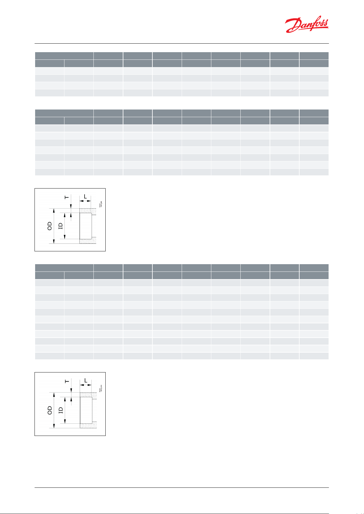
Table 4: Butt-weld ANSI (B 36.10 Schedule 40)
Figure 3: SD (DIN )
Table 5: Socket-Brazing DIN ( EN 1254-5)
Figure 4: SA (ASME)
© Danfoss | Climate Solutions | 2021.04 AI367729279610en-000101 | 4
SizeIDLODT
kv-angle
kv-straight
Cv-angle
Cv-straight
in.mmmmmmmm
m3/h
m3/h
USgal/min
USgal/min
¼
6.35
7.7
12.7
3.18
2.9
2.0
3.4
2.4⅜9.53815.88
3.18
4.5
3.2
5.2
3.6⅝15.88821.3
2.71
7.0
4.9
8.1
5.7⅞22.231126.9
2.34
14.6
10.2
16.9
11.81⅛28.581133.7
2.56
24.8
17.4
28.8
20.21⅜34.931542.4
3.74
42.6
29.8
49.4
34.61⅝41.281548.3
3.51
45.2
31.6
52.4
36.72⅛54
13.5
60.3
3.15806593762⅝66.7
13.5
76.1
4.70
12097140
1133⅛79.381588.9
4.76
182
152
211
1764⅛104.78
17.5
114.3
4.76
313
278
363
323
Copper pipe diameter
Tolerance
≥3mm up to ≤18 mm
±0,04 mm
Over 18 mm up to ≤28 mm
±0,05 mm
Over 28 mm up to ≤54 mm
±0,06 mm
Over 54 mm up to ≤76,1 mm
±0,07 mm
Over 76,1 mm up to ≤88,9 mm
±0,07 mm
Over 88,9 mm up to ≤108 mm
±0,07 mm
Size
[DN]
Parts program
Service
kit
(1)
Complete valve
Housing
Top complete
O-ring kit
for
SVA (cap)
FIA
ANG
STR
SVA-
S
(cap)
SVA-
L
(cap)
SCA-XCHV-XREG-SAREG-
SB
FIA
R717
Heat
Pump
R1270
Pro‐
py‐
lene
ANG
STR
ANG
STR
DIN
AN‐
SI
SDSADIN
AN‐
SI
SDSADIN
AN‐
SI
DIN
AN‐
SI
DIN
AN‐
SI
DIN
AN‐
SI
6xxxxxxxxxxx10xxxxxxxxxxxxxxx15xxxxxxxxxxxxxxxxxxx20xxxxxxxxxxxxxxxxxxx25xxxxxxxxxxxxxxxxxxx32xxxxxxxxxxxxxxxxxxx40xxxxxxxxxxxxxxxxxxx50xxxxxxxxxxxxxxxxx65xxxxxxxxxxxxxxxxx80xxxxxxxxxxxxxxxx
100xxxxxxxxxxxxxxxx
125xxxxxxxxxxxx
150xxxxxxxx
200xxxxxxxx
Hand operated regulating valve, type REG-SA and REG-SB 65
Table 6: Socket-Brazing ASME (ASME B16.50)
The design ts with all copper pipes having following tolerance to the nominal diameter.
Table 7: Tolerance for nominal diameter
Table 8: Available SVL products for 65 bar (943 psi)
(1)
(1)
To be used for SCA-X, CHV-X (all sizes) and REG-SA/SB (sizes 10 to 40).
To be used for SCA-X, CHV-X (all sizes) and REG-SA/SB (sizes 10 to 40).
x = Available
Design
Housing
Housing is Standard SVA angleway or straightway housing allowing other inserts from the SVL platform to be
installed. Material is special, cold resistant steel
© Danfoss | Climate Solutions | 2021.04 AI367729279610en-000101 | 5
P
S
6
5
/
9
4
3
p
s
i
g
R
E
G
U
L
A
T
I
N
G
V
A
L
V
E
R
E
G
-
S
A
D
N
1
5
½
”
@
–
6
0
°
C
\
–
7
6
°
F
→
1
5
0
°
C
\
3
0
2
°
F
Danfoss
M148B0099
Hand operated regulating valve, type REG-SA and REG-SB 65
The cone
The valves are available in two dierent versions – REG-SA with an A cone and REGSB with a B cone. The A cone is
designed for expansion lines, while the B cone is designed for regulating purposes e.g. liquid lines.
The valve cone is designed to ensure perfect regulation and provide an extensive regulating area. Irrespective of the
refrigerant used, it is easy to obtain the correct capacity. A cone seal ring provides perfect sealing at a minimum
closing momentum.
The valve cone can be turned on the spindle, thus there will be no friction between the cone and the seat when the
valve is opened and closed.
Spindle
The spindle is made of polished stainless steel, which is ideal for O-ring sealing.
Packing gland - REG-SA and REG-SB
The “full temperature range” packing gland ensures perfect tightness in the whole range: -60 °C /+150 °C (-76 °F /
+302 °F). The packing glands are equipped with a scraper ring to prevent penetration of dirt and ice.
Installation
Install the valve with the spindle up or in horizontal position. The ow must be directed towards the cone.
The valve is designed to withstand high internal pressure. However, the piping system in general should be
designed to avoid liquid traps and reduce the risk of hydraulic pressure caused by thermal expansion.
For further information refer to product instruction for REG-SA and REG-SB.
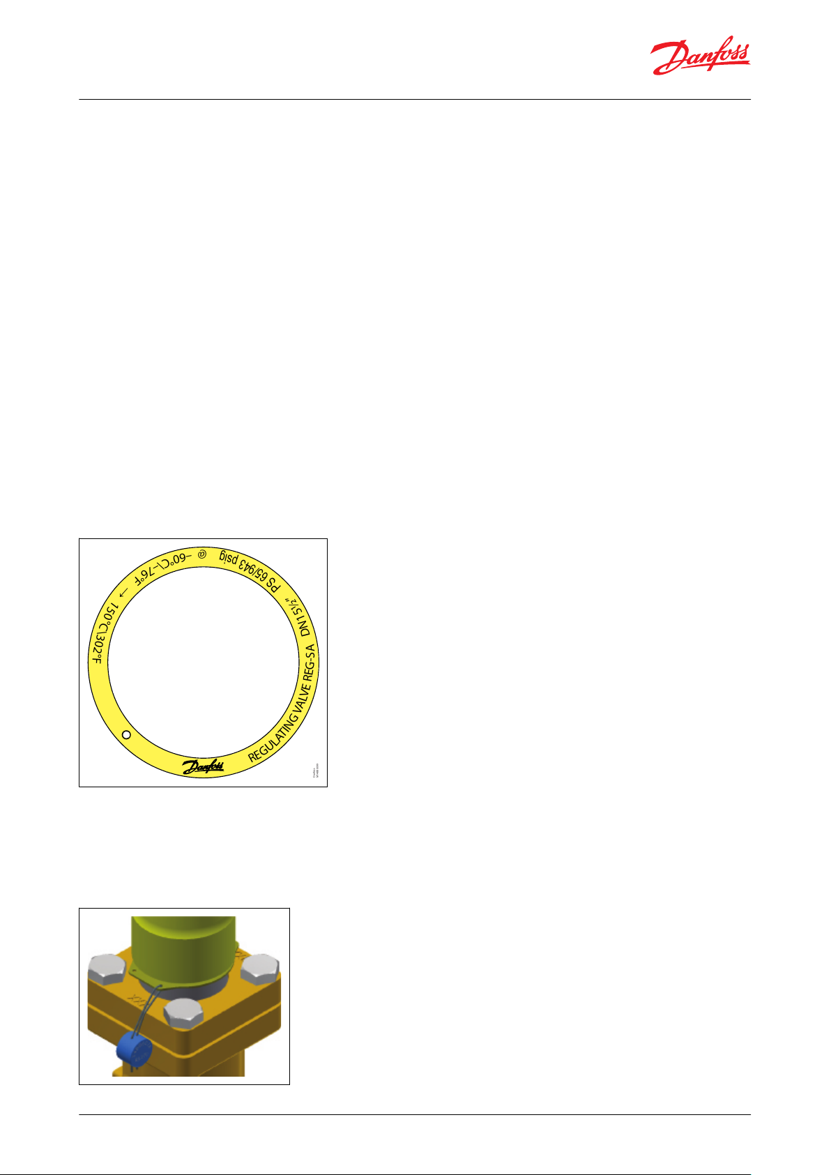
Figure 5: Example of marking ring, REG-SA
ID ring for special application
After converting a REG-SA/SB (DN 10-40) valve for Heat Pump/Propylene applications (replacing O-ring) the color
marked ID tag included in the service kit must be xed to the valve as shown in gure to the right.
The ID tag indicates the special application and identies the installed O-ring.
Figure 6: ID tag
© Danfoss | Climate Solutions | 2021.04 AI367729279610en-000101 | 6

Liquid line without phase change Liquid line with or without phase change
REG
Wet suction line
Dry suction line
Hot gas by-pass & defrost line
Discharge
line
kv[m
3
/h]
Quantity [m
3
/h] of water owing through a valve at a pressure loss of 1 bar (according to VDE/VDI Norm 2173).
P
1
[bar]
Pressure before the valve (upstream).
P
2
[bar]
Pressure after the valve (downstream).
Hand operated regulating valve, type REG-SA and REG-SB 65
Computation and selection
In refrigeration plants, regulating valves are primarily used in liquid lines in order to regulate the ow of refrigerant.
The valves can, however, also be used as expansion valves. From a calculation point of view the two elds of
application are very dierent.
Normal ow is the term used to describe the general case where the ow through the valve is proportional to the
square root of the pressure drop across it and inversely proportional to the density of the refrigerant (Bernouillis
equation).
This relationship between mass ow, pressure drop and density satises the majority of all valve applications with
refrigerants and brines.
Normal ow is characterised by turbulent ow through the valve without any phase change. The following capacity
curves are based on the above mentioned assumption.
Application of the regulating valves outside the normal ow area will reduce the capacity of the valve considerably.
In such cases it is recommended to use Coolselector®2.
Figure 7: Location of valve in system (marked with grey)
Sizing regulating valve for liquid ow
Liquid refrigerants: Use the liquid tables, Figure 13: REG-SA 25-40 and REG-SB 25-40, Figure 14: REG-SB 50, Figure 15:
REG-SB 65, Figure 16: Calculation factor CA, Figure 17: Flow rate diagram. For other refrigerants and brines, "Normal
ow" (Turbulent ow); see below and use the ow coecient tables (Figure 8: REG-SA 15-20 and REG-SB 15-20,
Figure 9: REG-SA 25-40 and REG-SB 25-40, Figure 10: REG-SB 50, Figure 11: REG-SB 65, Figure 12: REG-SA 15-20 and
REG-SB 15-20).
SI-units
Mass ow:
k
v
Volume ow:
k
v
© Danfoss | Climate Solutions | 2021.04 AI367729279610en-000101 | 7
=
ρ × 1000 × Δp
∨
=
1000 × Δp
G
= G × CA[m3/h]
[m3/h]
ρ

Δp
[bar]
Actual pressure loss across the valve (P1–P2).
G
[kg/h]
Mass ow through the valve.
V
[m3/h]
Volume ow through the valve.
ρ
[kg/m3]
Density of the refrigerant before the valve.
C
A
Calculation factor (See Figure 18: Calculation factor CA).
C
v
[US gal/min]
Quantity [US gal/min] of water owing through a valve at a pressure loss of 1 psi.
P
1
[psi]
Pressure before the valve (upstream).
P
2
[psi]
Pressure after the valve (downstream).
Δp
[psi]
Actual pressure loss across the valve (P1–P2).
G
[lb/min]
Mass ow through the valve.
V
[US gal/min]
Volume ow through the valve.
ρ
[lb/ft3]
Density of the refrigerant before the valve.
C
A
Calculation factor (See Figure 18: Calculation factor CA).
B
A
0
0
0% 25% 50% 75% 100%
Turn of spindle
Opening
kv(Cv)
0.5
1
1.5
2
2.5
3
3.5
4
4.5
5
1 2 3 4 5 6 7 8 9
(5.80)
(5.22)
(4.64)
(4.06)
(3.48)
(2.90)
(2.32)
(1.74)
(1.16)
(0.58)
Flow coefficient
Danfoss
M148B0013_1
Hand operated regulating valve, type REG-SA and REG-SB 65
Imperial units
Mass ow:
0.95 × G
Cv=
ρ × Δp
= 31.6 × G × CA[USgal/ min . ]
Volume ow:
0.127 × ∨
Cv=
[USgal/ min . ]
Δp
ρ
Figure 8: REG-SA 15-20 and REG-SB 15-20
© Danfoss | Climate Solutions | 2021.04 AI367729279610en-000101 | 8

B
A
0% 25% 50% 75% 100%
Turn of spindle
Opening
kv(Cv)
0
2
4
6
8
10
12
14
16
18
20
0 1 2 3 4 5 6 7 8 9 10 11 12
(23.20)
(20.88)
(18.56)
(16.24)
(13.92)
(11.60)
(9.28)
(6.96)
(4.64)
(2.32)
Flow coefficient
Danfoss
M148B0014_1
B
0% 25% 50% 75% 100%
Turn of spindle
Flow coefficient
Opening
kv(Cv)
0
5
10
15
20
25
30
35
40
45
0 1 2 3 4 5 6 7 8 9 10 11 12 13
(52.2)
(46.4)
(40.6)
(34.8)
(29.0)
(23.2)
(17.4)
(11.6)
(5.8)
Danfoss
M148B0015_1
Hand operated regulating valve, type REG-SA and REG-SB 65
Figure 9: REG-SA 25-40 and REG-SB 25-40
Figure 10: REG-SB 50
© Danfoss | Climate Solutions | 2021.04 AI367729279610en-000101 | 9

B
0% 25% 50% 75% 100%
Turn of spindle
Flow coefficient
Opening
kv(Cv)
0
10
20
30
40
50
60
70
80
0 1 2 3 4 5 6 7 8 9 10 11 12 13 14 15
(92.8)
(81.2)
(69.6)
(58.0)
(46.4)
(34.8)
(23.2)
(11.6)
Danfoss
M148B0016_1
0
1
2
3
4
5
6
7
8
9
0%
25%
50%
75%
100%
Turn of spindle
A
B
Turn of spindle
Opening
kg/h
(lb/min)
8000
(294)
4000
(147)
R717
∆P = 0.5 bar (7 psi)
∆P = 1 bar (14 psi)
∆P = 1.5 bar (22 psi)
∆P = 2 bar (29 psi)
Hand operated regulating valve, type REG-SA and REG-SB 65
Figure 11: REG-SB 65
Liquid R 717, density: 670 kg/m3 [42 lb/ft3]
Figure 12: REG-SA 15-20 and REG-SB 15-20
© Danfoss | Climate Solutions | 2021.04 AI367729279610en-000101 | 10

kg/h
(lb/min)
30000
(1103)
20000
(735)
B
A
10000
(368)
∆P = 0.5 bar (7 psi)
∆P = 1 bar (14 psi)
∆P = 1.5 bar (22 psi)
∆P = 2 bar (29 psi)
0
1
2
3
4
5
6
7
8
9
10
11
12
Turn of spindle
R717
Opening
0%
25%
50%
75%
100%
∆P = 2 bar (29 psi)
∆P = 1.5 bar (22 psi)
∆P = 1 bar (14 psi)
∆P = 0.5 bar (7 psi)
kg/h
(lb/min)
60000
(2206)
45000
(1654)
B
30000
(1103)
15000
(551)
Turn of spindle
R717
0
1
2
3
4
0%
25%
50%
75%
100%
5
6
7
8
9
10
11
12
13
Opening
Hand operated regulating valve, type REG-SA and REG-SB 65
Figure 13: REG-SA 25-40 and REG-SB 25-40
Liquid R 717, density: 670 kg/m3 [42 lb/ft3]
Figure 14: REG-SB 50
© Danfoss | Climate Solutions | 2021.04 AI367729279610en-000101 | 11

∆P = 2 bar (29 psi)
∆P = 1.5 bar (22 psi)
∆P = 1 bar (14 psi)
∆P = 0.5 bar (7 psi)
kg/h
(lb/min)
100000
(3676)
75000
(2757)
B
50000
(1838)
25000
(919)
Turn of spindle
R717
0
1
2
6
0%
25%
50%
75%
100%
3
4
5
7
8
9
10
11
12
13
14
15
Opening
Hand operated regulating valve, type REG-SA and REG-SB 65
Figure 15: REG-SB 65
Liquid R 717, density: 670 kg/m3 [42 lb/ft3]
Figure 16: Calculation factor C
NOTE:
For choice of valve size and connection see "Connections".
© Danfoss | Climate Solutions | 2021.04 AI367729279610en-000101 | 12
A

2200
(81)
0
1
2
3
4
5
6
7
8
9
0%
25%
50%
75%
100%
Turn of spindle
A
B
Turn of spindle
Opening
∆P = 2 bar (29 psi)
∆P = 1.5 bar (22 psi)
∆P = 1 bar (14 psi)
∆P = 0.5 bar (7 psi)
kg/h
(lb/min)
8000
(294)
4000
(147)
R717
REG-SA 15-20 and REG-SB 15-20
Hand operated regulating valve, type REG-SA and REG-SB 65
Computation and selection Example 1
Refrigerant: R 717
Refrigerant ow: 2200 kg/h
Pressure drop: Δp = 0.5 bar
The above mentioned example is illustrated on the following ow rate diagram and shows that REG-SB 15 and 20
with cone B can be used. The main rule is that nominal regulation range should be below 85% opening degree. If
the arrowline is crossing 2 cone curves, the smaller cone should be selected if opening degree < 85%.
The example is only correct if the density of the refrigerant is approx. 670 (kg/m3), and there must be no build-up of
ash gas in the valve.
Figure 17: Flow rate diagram
Computation and selection Example 2
Brine, density ρ: 1150 [kg/m3]
Brine ow G: 2,700 [kg/h]
Pressure drop Δp: 0.5 [bar]
In this example it is not possible to use the selection diagrams (Figure 12: REG-SA 15-20 and REG-SB 15-20, Figure
13: REG-SA 25-40 and REG-SB 25-40, Figure 14: REG-SB 50, Figure 15: REG-SB 65) as the refrigerant in question is not
included.
Use the curves of the kv-values instead (Figure 8: REG-SA 15-20 and REG-SB 15-20, Figure 9: REG-SA 25-40 and REG-
SB 25-40, Figure 10: REG-SB 50, Figure 11: REG-SB 65) and calculate the required kv by means of the formulas in the
"Introduction" passage at the beginning of this chapter. Alternatively calculate the kv-values by means of the
calculation factor CA (Figure 18: Calculation factor CA) and the ow rate diagram (in this example: Figure 19: Flow rate
diagram) as per the following calculation example.
Required kv-value
CA = 0.00132 (from Figure 18: Calculation factor CA)
© Danfoss | Climate Solutions | 2021.04 AI367729279610en-000101 | 13

Density kg/m3
[lb/ft]
B
A
0
0
0% 25% 50% 75% 100%
Turn of spindle
Opening
kv(Cv)
0.5
1
1.5
2
2.5
3
3.5
4
4.5
5
1 2 3 4 5 6 7 8 9
(5.80)
(5.22)
(4.64)
(4.06)
(3.48)
(2.90)
(2.32)
(1.74)
(1.16)
(0.58)
3.56 m3/h
(from
calculation
above)
Danfoss
M148B0023_1
Hand operated regulating valve, type REG-SA and REG-SB 65
kv = CA × G
kv = 0.00132 × 2,700 [kg/h]
= 3.56 [m3/h]
Calculation example:
Figure 18: Calculation factor C
Figure 19: Flow rate diagram
A
REG-SB 15 and REG-SB 20 with cone B can be used.
© Danfoss | Climate Solutions | 2021.04 AI367729279610en-000101 | 14
Danfoss
M148B0010_1
Danfoss
M148B0009_1
Danfoss
M148B0011_1
17
11
8
9
12
13
4
18
18
10
7
2
3A
1
21
5
22
17
11
8
10
7
3A
19
7
4
20
1
22
17
4
8
11
18
10
9
7
3B
12
13
21
5
1
REG-SB 50 - 65REG-SA and REG-SB 15 - 40REG-SA and REG-SB 10
No.
Part
Material
EN
ISO
ASTM
1
Housing
Steel
G20Mn5QT, 10213-3
P285QH+QT, 10222-4
LCC, A352
LF2, A350
2
DN 15 - 40 (½ - 1½ in.) – Bonnet, Flange
Steel
P275NL1 or 2 EN10028-3
A, A662
3A
DN 15 - 40 (⅜ - 1½ in.) – Bonnet, Insert
Steel
11SMn30
10087
Type 2, R 683-9
1213
SAE J403
3B
DN 50 - 65 (2 - 2½ in.) – Bonnet, Flange
Steel
P285QH+QT
10222-4
LF2
A350
4
Spindle - DN 15 - 65 (¼ - 2½ in.)
Stainless steel
X8CrNiS 18-9, 17440
Type 17, 683/13
AISI 303
5
Cone
Steel7Packing washer
Aluminium
8
Packing gland
Stainless Steel
X8CrNiS 18-9, 10088
Type 17, 683/13
AISI 303
9
O-ring
Chloroprene (Neoprene)
10
Spring loaded Teon ring
PTFE11O-ring
Chloroprene (Neoprene)
12
Bolts
High temperature steel
42CrMo5
10269
A193
13
Gasket
Fiber, non asbestos
14
Bottom insert
Steel17Seal cap
Aluminium
18
Gasket f. seal cap
Nylon19Locking nut
Steel20Screw
Steel21Disk spring
Steel22O-ring
Chloroprene (Neoprene)
(1)
Hand operated regulating valve, type REG-SA and REG-SB 65
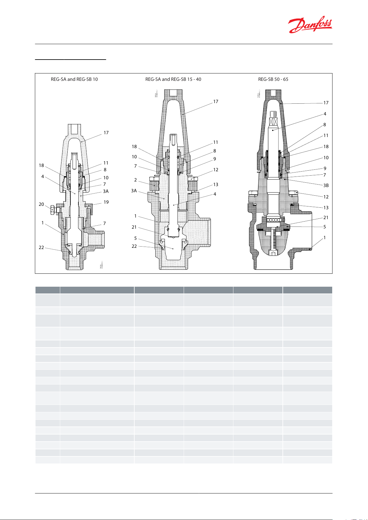
Material specication
Figure 20: REG-SA and REG-SB 10 - 65
Table 9: Material and part list
(1)
(1)
To be replaced in R717 Heat Pump and R1270 Propylene applications.
To be replaced in R717 Heat Pump and R1270 Propylene applications.
© Danfoss | Climate Solutions | 2021.04 AI367729279610en-000101 | 15

REG-SA and REG-SB 15 - 40
REG-SB 50 - 65
øD
C
G
G
H
H
G
G
C
øD
Valve sizeCG∅DH
Weight
REG-SA/SB 15-20mm1824538601.4 kg
REG-SA/SB (½-¾)
in.
7.17
1.77
1.50
2.36
3.1 lb
REG-SA/SB 25-40mm2375550702.4 kg
REG-SA/SB (1-1½)
in.
9.33
2.17
1.97
2.76
5.3 lb
REG-SB 50mm3156050773.2 kg
REG-SB (2 in.)
in.
12.4
2.36
1.97
3.03
7.1 lb
REG-SB 65mm3357050904.8 kg
REG-SB (2½ in.)
in.
13.19
2.76
1.97
3.54
10.6 lb
Hand operated regulating valve, type REG-SA and REG-SB 65
Dimensions and weights
Figure 21: REG-SA and REG-SB 15 - 65 in angleway version
Table 10: REG-SA and REG-SB 15 - 65 in angleway version
NOTE:
Specied weights are approximate values only.
© Danfoss | Climate Solutions | 2021.04 AI367729279610en-000101 | 16

REG-SA and REG-SB 15 - 40
øD
G
B H
E
C
Dan
fo
ss
M148B0042_1
REG-SB 50-65
øD
K
C
E
G
B
H
Valve sizeCBEG∅DH
Weight
REG-SA/SB 15-20
mm
145
155201203860
2.0 kg
REG-SA/SB (½-¾)
in.
5.71
6.10
0.79
4.72
1.50
2.36
4.4 lb
REG-SA/SB 25-40
mm
200
215261555070
3.0 kg
REG-SA/SB (1-1½)
in.
7.87
8.46
1.02
6.10
1.97
2.76
6.6 lb
REG-SB 50mm257
250321485077
4.2 kg
REG-SB (2 in.)
in.
10.12
10.20
1.26
5.83
1.97
3.03
9.3 lb
REG-SB 65mm280
284401765090
6.3 kg
REG-SB (2½ in.)
in.
11.02
11.18
1.57
6.93
1.97
3.54
13.9 lb
Hand operated regulating valve, type REG-SA and REG-SB 65
Figure 22: REG-SA and REG-SB 15 - 40 in straightway
version
Figure 23: REG-SB 50-65 in straightway version
Table 11: REG-SA and REG-SB 15 - 65 in straightway version
NOTE:
Specied weights are approximate values only.
© Danfoss | Climate Solutions | 2021.04 AI367729279610en-000101 | 17

Size
[DN]
Parts Program
Service kit
(1)
Housing
Top complete
O-ring kit for
ANG
STR
REG-SA
REG-SB
R717 Heat
Pump
R1270
Propylene
DIN
ANSISDSA
DIN
ANSISDSA
6
148B6689
148B6687
148B6722
148B6711
148B6693
148B6691
148B6743
148B6732
10
148B6690
148B6688
148B6723
148B6712
148B6694
148B6692
148B6744
148B6733
148B5761
148B5764
148B6084
148B6085
15
148B6622
148B6612
148B6724
148B6713
148B6642
148B6632
148B6745
148B6734
148B5762
148B5765
148B6070
148B6077
20
148B6623
148B6613
148B6725
148B6714
148B6643
148B6633
148B6746
148B6735
148B5762
148B5765
25
148B6624
148B6614
148B6726
148B6715
148B6644
148B6634
148B6747
148B6736
148B5763
148B5766
148B6071
148B6096
(2)
148B6078
148B6097
(2)
32
148B6625
148B6615
148B6727
148B6716
148B6645
148B6635
148B6748
148B6737
148B5763
148B5766
40
148B6626
148B6616
148B6728
148B6717
148B6646
148B6636
148B6749
148B6738
148B5763
148B5766
50
148B6627
148B6617
148B6718
148B6647
148B6637
148B6739
148B5767
148B6072
148B6079
65
148B6628
148B6618
148B6729
148B6719
148B6648
148B6638
148B6750
148B6740
148B5768
148B6073
148B6080
80
148B6629
148B6619
148B6730
148B6720
148B6649
148B6639
148B6751
148B6741
148B6074
148B6081
100
148B6630
148B6620
148B6731
148B6721
148B6650
148B6640
148B6752
148B6742
148B6075
148B6082
125
148B6631
148B6621
148B6651
148B6641
148B6076
148B6083
150
200
SVL valves are approved according to the European standard specied in the Pressure Equipment Directive and are CE
marked.
REG-SA and REG-SB
Nominal bore
DN≤ 25 mm (1 in.)
DN32-80 mm (1¼ - 3 in.)
DN100 - 200 mm (4-8 in.)
Classied
for
Fluid group I
Category
Article 3, paragraph 3
II
III
File name
Document type
Approval authority
03709-F0 BV
Marine - Safety
Certicate
BV
TAP0000002 Rev. 2
Marine - Safety
Certicate
DNV GL
EU 033F0685.AK
EU Declaration
Danfoss
MD 033F0691.AE
Manufacturers Declaration
Danfoss
19.10048.266
Marine - Safety
Certicate
RMRS
Hand operated regulating valve, type REG-SA and REG-SB 65
Ordering
Table 12: Ordering for REG-SA and REG-SB 65 bar (943 psi) series
(1)
(1)
To be used for REG SA/SB (all sizes)
To be used for REG SA/SB (all sizes)
(2)
(2)
To be used for REG SA/SB, 25-40
To be used for REG SA/SB, 25-40
Certicates, declarations, and approvals
The list contains all certicates, declarations, and approvals for this product type. Individual code number may have
some or all of these approvals, and certain local approvals may not appear on the list.
Some approvals may change over time. You can check the most current status at danfoss.com or contact your local
Danfoss representative if you have any questions.
Table 13: Pressure Equipment Directive (PED)
For further details / restrictions - see Installation guide.
Table 14: REG-SA and REG-SB
Table 15: Certicates and declarations
© Danfoss | Climate Solutions | 2021.04 AI367729279610en-000101 | 18

Online support
Danfoss oers a wide range of support along with our products, including digital product information, software,
mobile apps, and expert guidance. See the possibilities below.
The Danfoss Product Store
The Danfoss Product Store is your one-stop shop for everything product related—no matter where
you are in the world or what area of the cooling industry you work in. Get quick access to essential
information like product specs, code numbers, technical documentation, certications, accessories,
and more.
Start browsing at store.danfoss.com.
Find technical documentation
Find the technical documentation you need to get your project up and running. Get direct access to
our ocial collection of data sheets, certicates and declarations, manuals and guides, 3D models
and drawings, case stories, brochures, and much more.
Start searching now at www.danfoss.com/en/service-and-support/documentation.
Danfoss Learning
Danfoss Learning is a free online learning platform. It features courses and materials specically
designed to help engineers, installers, service technicians, and wholesalers better understand the
products, applications, industry topics, and trends that will help you do your job better.
Create your Danfoss Learning account for free at www.danfoss.com/en/service-and-support/learning.
Get local information and support
Local Danfoss websites are the main sources for help and information about our company and
products. Find product availability, get the latest regional news, or connect with a nearby expert—all
in your own language.
Find your local Danfoss website here: www.danfoss.com/en/choose-region.
Spare Parts
Get access to the Danfoss spare parts and service kit catalog right from your smartphone. The app
contains a wide range of components for air conditioning and refrigeration applications, such as
valves, strainers, pressure switches, and sensors.
Download the Spare Parts app for free at www.danfoss.com/en/service-and-support/downloads.
Coolselector®2 - nd the best components for you HVAC/R system
Coolselector®2 makes it easy for engineers, consultants, and designers to nd and order the best
components for refrigeration and air conditioning systems. Run calculations based on your operating
conditions and then choose the best setup for your system design.
Download Coolselector®2 for free at coolselector.danfoss.com.
Danfoss can accept no responsibility for possible errors in catalogues, brochures and other printed material. Danfoss reserves the right to alter its
products without notice. This also applies to products already on order provided that such alterations can be made without subsequential
changes being necessary in specications already agreed. All trademarks in this material are property of the respective companies. Danfoss and
the Danfoss logotype are trademarks of Danfoss A/S. All rights reserved.
© Danfoss | Climate Solutions | 2021.04 AI367729279610en-000101 | 19
 Loading...