

Page 1
Data Sheet
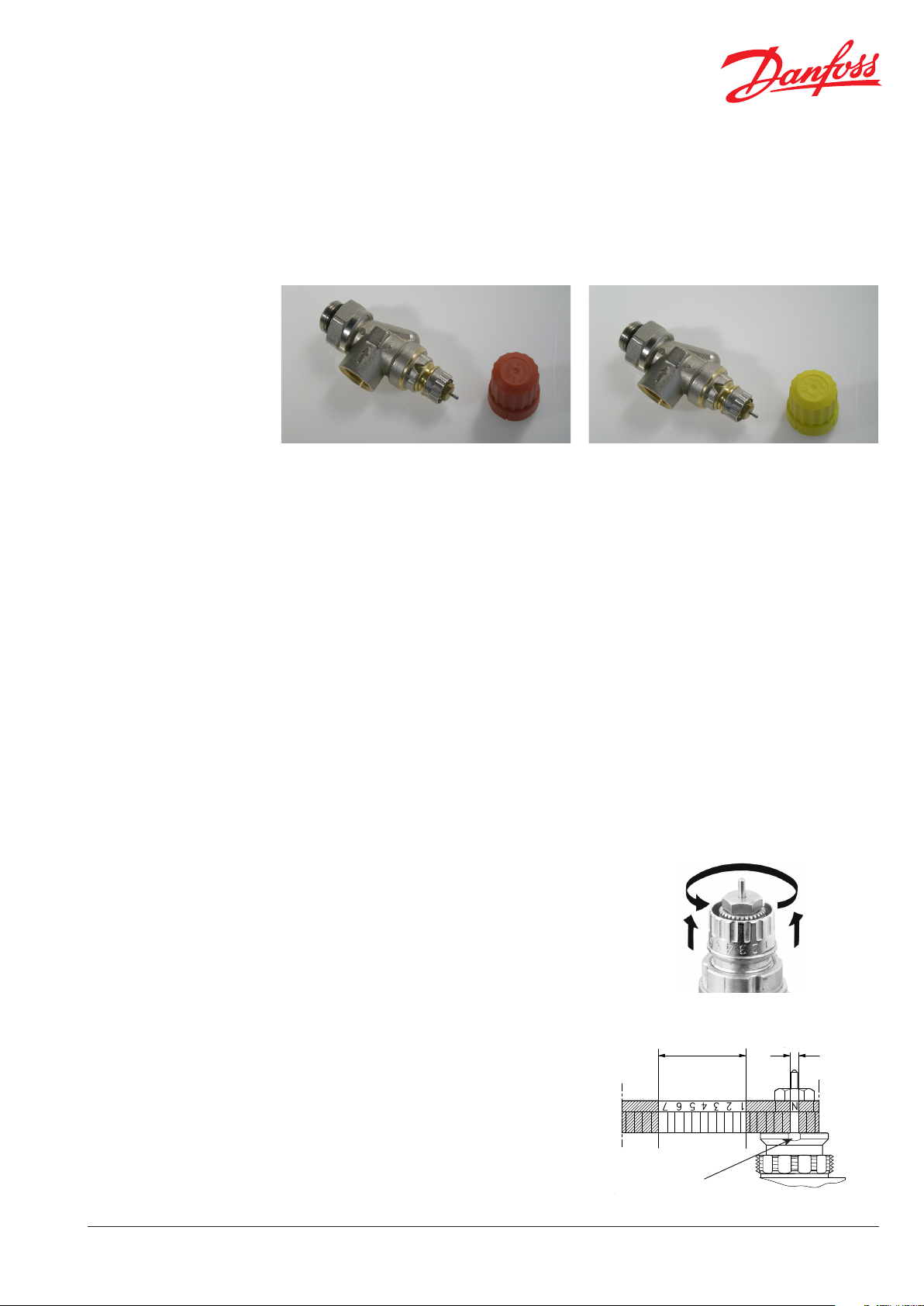
Radiator Valves with Integrated Presetting, Types
RA-N, 013G3301* and RA-U, 013G3302
Application
Quality, approvals
Presetting
RA-N and RA-U valve bodies are used with all types of thermostatic sensors with RA 2000 connection and with TWA-A thermal actuators.
Both valves are designed for two-pipe heating
systems.
The valves features an integrated pre-setting of
maximum water ow.
The setting range is:
RA-N, 013G3301: kv = 0.16 - 1.02 m3/h
RA-U, 013G3302: kv = 0.03 - 0.73 m3/h
The protective valve cap (red or yellow) may be
used for manual regulation during the building
period, until the sensor is tted.
All Danfoss radiator thermostats are manufactured in factories, assessed and certied by BSI
(British Standards Institution) against ISO 9000
and ISO14001.
The presetting values of RA-N and RA-U valves
can be adjusted easily and accurately without the
use of tools (factory setting = N):
RA-N valve bodies are manufactured from brass
with nickel plating.
The pressure pin of the gland seal is of chromium
steel and works in a lifetime lubricated O-ring. The
complete gland seal assembly can be replaced
without draining down the system.
In order to avoid deposition and corrosion the
composition of the hot water must be in accordance
with the VDI 2035 guideline (Verein Deutscher
Ingenieure).
It is recommended that formulations containing
mineral oil are avoided.
* RA-N, code 013G3301, is Keymarked certied
according to EN215.
Danfoss Heating Solutions
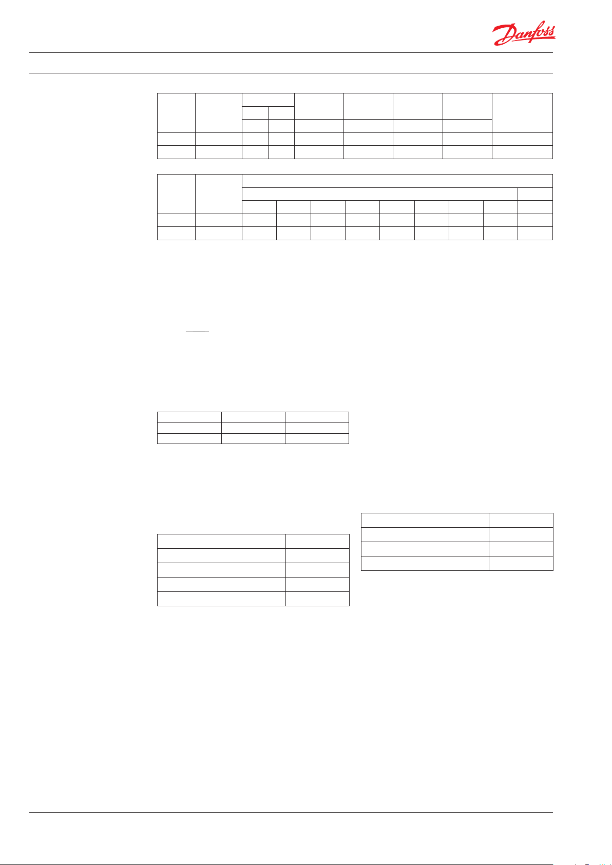
• Remove protective cap / thermostatic sensor
• Find reference mark
• Lift and turn setting ring until the required
setting aligns with the reference mark.
Presetting can be selected in steps from 1 to 7.
At setting N the valve is fully open. This setting is
used when ushing or draining the system.
Settings other than the recommended range
should be avoided.
When the thermostatic sensor has been installed,
the presetting is protected against unintended
regulation.
VDSXJ202 © Danfoss 03/2011
Presetting
Reference mark
range
Factory setting and
one-pipe system
1
Page 2
Data Sheet Radiator Valves with Integrated Presetting, Types RA-N, 013G3301* and RA-U, 013G3302
Data and ordering
Max. di.
press.
2)
Test
Max. work.
temp.
Code noInlet Outlet
Type Design
Connections
Max. work.
press.
Rp R bar bar bar ˚C
RA-N 15 Horiz. angle 1/2 1/2 10 0.6 16 120 013G3301
RA-U 15 Horiz. angle 1/2 1/2 10 0.6 16 120 013G3302
Pre-setting
Type Design
kv-max.1) (m3/h at Δp = 1 bar) k
vs
1 2 3 4 5 6 7 N N
RA-N 15 Horiz. angle 0.16 0.20 0.25 0.35 0.47 0.59 0.74 0.81 1.00
RA-U 15 Horiz. angle 0.03 0.06 0.10 0.19 0.27 0.39 0.44 0.62 0.73
1)
Working pressure = static + dierential pressure. The maximum dierential pressure specied is the maximum pressure at which
the valves give satisfactory regulation. As with any device which imposes a pressure drop in the system, noise may occur under
certain ow/pressure conditions. To ensure quiet operation, maximum pressure drop should not exceed 30 to 35 kPa. The dierential pressure can be reduced by the use of the Danfoss dierential pressure regulators types AVD, AVDL, AVDS, IVD or ASV-P.
2)
The kv-value indicates the water ow (Q) in m3/h at a pressure drop (∆p) across the valve of 1 bar;
kv =
Q
√∆p
At setting N the kv-value is stated according to EN 215, at XP = 2K i.e. the valve is closed at 2°C
higher room temperature. At lower settings the XP value is reduced to 0.5K of the setting value 1. The kvs-value states the ow Q
at a maximum lift, i.e. at fully open valve at setting N. When using remote setting adjusters or RAE sensors kv values are reduced
for identical P-band
Technical data
Kv (Xp=2) kvs
RA-N 0.62 1.00
RA-U 0.44 0.73
Parts in contact with water
Valve body and other metal parts Ms 58, brass
Kv-limiter PPS
O-ring EPDM
Valve cone NBR
Pressure pin and valve spring Chrome steel
The valve bodies are nickel-plated.
Max. ambient temperature 60 ˚C
Max. medium temperature 120 ˚C
Max. working pressure 10 bar
Test pressure 16 bar
2
VDSXJ202 © Danfoss 03/2011
Danfoss Heating Solutions
Page 3

Data Sheet Radiator Valves with Integrated Presetting, Types RA-N, 013G3301* and RA-U, 013G3302
Dimensions
The valve tailpiece features an o-ring seal to ensure easy and safe mounting. The mating part of the radiator must be
chamfered 45˚ in order to prevent damage of the seal. See illustration.
RA-N, 013G3301Capacities
Danfoss Heating Solutions
VDSXJ202 © Danfoss 03/2011
3
Page 4

Data Sheet Radiator Valves with Integrated Presetting, Types RA-N, 013G3301* and RA-U, 013G3302
RA-U, 013G3302
Danfoss A/S
Residential Heating
Haarupvaenget 11
8600 Silkeborg
Denmark
Phone:+45 7488 8000
Fax: +45 7488 8100
Email: heating.solutions@danfoss.com
www.heating.danfoss.com
Sizing example:
Required heat: 1.5 kW
Cooling across radiator: 20° C
Flow through
radiator:
Pressure drop across valve: ∆p = 1 mwg
Valve setting: RA-N, 013G3301 2
1.5
Q =
= 0.064 m3/h= 0.018 l/s
20 x 1.16
RA-U, 013G3302 5
Alternatively the setting can be read directly in the table
"Data and Ordering".
Q (m3/h)
kv =
√∆p (bar)
4
VDSXJ202 © Danfoss 03/2011
Danfoss Heating Solutions
 Loading...