

Page 1
Data Sheet
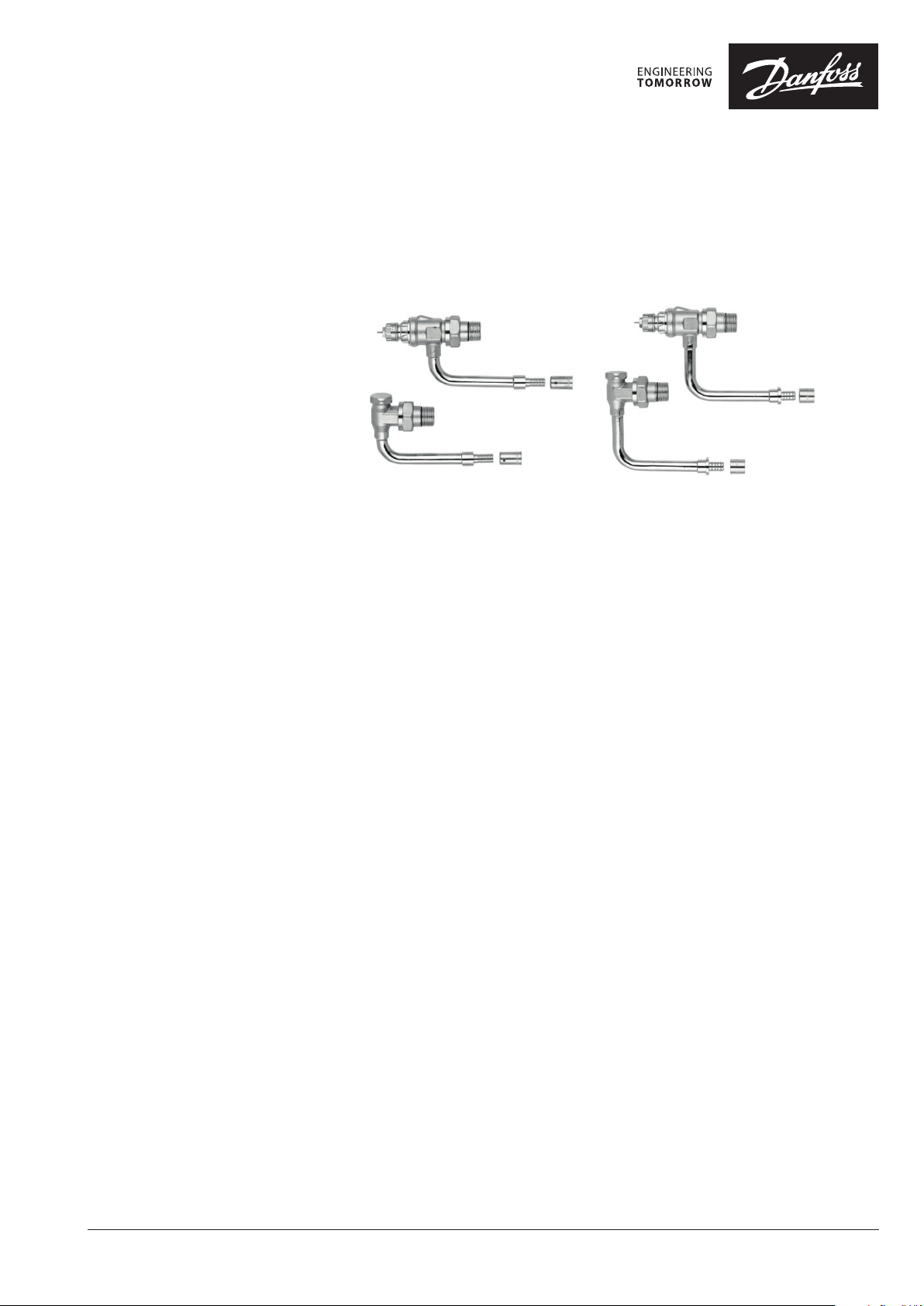
Valve Set for Hydro Cable - Valve Body RA-N/HC
& Lockshield Valve RLV-S/HC
with self sealing tail piece
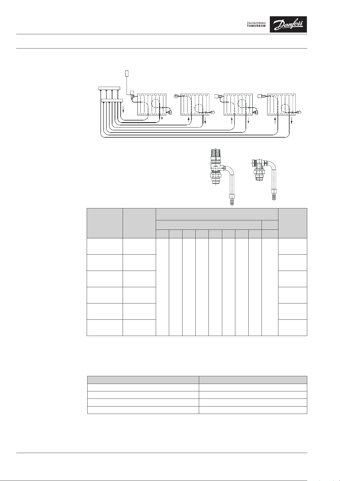
Application
RA-N/HC and RLV-S/HC,
radial
RA-N/HC radiator valve
All RA-N/HC valve bodies can be used together with all types of thermostatic elements
with Danfoss RA connection in two-pipe
heating systems.
RA-N/HC valves are fitted with a kv limiting
device for presetting of max. water flow within
a range of 0.04 to 0.69 m3/h.
The valve bodies are supplied with a protective cap which can be used for manual regulation during the construction phase. The protective cap must not be used as a manual shut
off device. A special manual shut off device
(code no. 013G5002) should be used.
To be able to distinguish between other valve
bodies of the RA 2000 series the RA-N/HC
protective cap is red.
RA-N/HC has a connection for PEX 12 x 1.1 mm
and 16 x 1.5 mm hydro cable, both axial and
radial compression fittings are available. RA-N/
HC are also available with 1/2” conection.
RA-N/HC and RLV-S/HC,
axial
RLV-S/HC lockshield valve
RLV-S/HC is intended for mounting on the
outlet of the radiator.
Using RLV-S/HC each radiator can be shut off
individually to allow trouble-free maintenance or repair without affecting other radiators
in the system.
RLV-S/HC is available in angle version with a
connection for PEX 12 x 1.1 mm and 16 x 1.5
mm hydro cable, both axial and radial compression fittings are available.
RLV-S/HC is also available with 1/2” connection.
Default setting is fully open valve.
Dimensions correspond to DIN 3842-1.
In order to avoid deposition and corrosion
the composition of the hot water must be in
accordance with the VDI 2035 guideline
(Verein Deutscher Ingenieure).
Valve bodies are manufactured from brass
with nickel plating. The pressure pin of the
gland seal is of chrominium steel and works
in a lifetime lubricated O-ring. The complete
gland assembly can be replaced without draining down the system.
Should water treatment be used it is essential
that dosing instructions of the manufacturer
are strictly observed. It is recommended that
formulations containing mineral oil are avoided.
VDLXB102 © Danfoss 02/2017 1
Page 2
Datasheet Valve Set for Hydro Cable - Valve Body RA-N/HC & Lockshield Valve RLV-S/HC
Principles
Closing and Opening RLV-S/HC
Use an 8 mm Allen key to close the RLV-S/HC
by turning it clockwise.
Open the RLV-S/HC by turning the Allen key
anti-clockwise. With 4 turns the valve will be
fully open.
Technical Data
and Ordering
Presetting
RA-N/HC &
RLV-S/HC
RA-N/HC UK 50
RLV-S/HC 45
RA-N/HC UK 50
RLV-S/HC 45
RA-N/HC UK 75
RLV-S/HC 75
RA-N/HC UK 75
RLV-S/HC 75
RA-N/HC UK 50
RLV-S/HC 45
RA-N/HC UK 75
RLV-S/HC 75
1) The kv-value indicates the water flow (Q) in m3/h at a pressure drop (Δp) across the valve of 1 bar; kv = Q: √Δp. The
kv-value is stated according to EN 215, at XP = 2K, i.e. the valve is closed at 2°C higher room temperature. At lower
settings the XP value is reduced to 0.5K. The kvs-value states the flow Q at a maximum lift, i.e. at fully open valve.
2) Kvs-value for RLV-S/HC: 1.26 m3/h
Design
1 2 3 4 5 6 7 N N
Radial 12mm
Radial 16mm 013G2291
Radial 12mm 013G2292
0.04 0.06 0.10 0.15 0.21 0.28 0.36 0.44 0.69
Radial 16mm 013G2293
Axial 12mm 013G2294
Axial 12mm 013G2295
kv-value¹⁾ Kvs ²⁾
Code No.
013G2290
Technical Data
Max. working pressure³⁾ 10 bar
Max. differential pressure 0.6 bar
Test pressure 16 bar
Max. working temperature 120 °C
3) Working pressure = static + differential pressure. The maximum differential pressure specified is the maximum
pressure at which the valves give satisfactory regulation. As with any device which imposes a pressure drop in the
system, noise may occur under certain flow/pressure conditions. To ensure quiet operation, maximum pressure drop
should not exceed 30 to 35 kPa. The differential pressure can be reduced by the use of the Danfoss differential pressure regulators.
VDLXB102 © Danfoss 02/2017 2
Page 3

Datasheet Valve Set for Hydro Cable - Valve Body RA-N/HC & Lockshield Valve RLV-S/HC
1
2
3
4
5
6
7
8
9
2
11
12
7
8
9
6
10
Capacities
Construction
Note!
As with any device which imposes a pressure drop in the system, noise may occur under certain flow/pressure
conditions. To ensure quiet operation, maximum pressure drop should not exceed 30-35 kPa (3-3,5 mwg).
1. Gland seal
2. O-Ring
3. Pressure pin
4. Seal
5. Regulation spring
6. Elbow
7. Valve body
8. Union nut
9. Self sealing tail piece
10. Fitting
11. Cover cap
12. Shut off spindle
Valve body and other metal parts Brass, CuZn4Pb2
O-ring EPDM
Valve cone NBR
Pressure pin and valve spring Steel/chrome
Elbow Copper
The valve bodies are nickle-plated on the outside.
3 VDLXB102 © Danfoss 02/2017
Page 4

Datasheet Valve Set for Hydro Cable - Valve Body RA-N/HC & Lockshield Valve RLV-S/HC
Dimensions
55
Code no.
013G2290
L2
S1
96 L3
S2
d2
RA-N/HC
RA-N/HC
RLV-S/HC
RA-N/HC UK 50
RLV-S/HC 45 15 24 R ¹/₂ 45 112,5 53 21 30
Design
Radial
12mm
D1 D2
15 - R ¹/₂ 50 112,5 72,6 24 30
ISO
7-1
D
L1
S1
D2
L3
S2
d2
RLV-S/HC
L1 L2 L3
D1
L1
Arc.flats
d2 S1 S2
L2
Danfoss A/S
Heating Solutions
Haarupvaenget 11
8600 Silkeborg
Denmark
Phone: +45 7488 8000
Fax: +45 7488 8100
e-mail: heating.solutions@danfoss.com
www.heating.danfoss.com
013G2291
013G2292
013G2293
013G2294
013G2295
RA-N/HC UK 50
RLV-S/HC 45 15 24 R ¹/₂ 45 113,5 53 21 30
RA-N/HC UK 75
RLV-S/HC 75 15 24 R ¹/₂ 75 112,5 53 21 30
RA-N/HC UK 75
RLV-S/HC 75 15 24 R ¹/₂ 75 113,5 53 21 30
RA-N/HC UK 50
RLV-S/HC 45 19 24 R ¹/₂ 45 107,5 53 21 30
RA-N/HC UK 75
RLV-S/HC 75 19 24 R ¹/₂ 75 107,5 53 21 30
Radial
16mm
Radial
12mm
Radial
16mm
Axial
12mm
Axial
12mm
15 - R ¹/₂ 50 113,5 72,5 24 30
15 - R ¹/₂ 75 112,5 72,6 24 30
15 - R ¹/₂ 75 113,5 72,6 24 30
19 - R ¹/₂ 50 107,5 72,6 24 30
19 - R ¹/₂ 75 107,5 72,6 24 30
3 VDLBX102 © Danfoss 02/2017
 Loading...