

Data Sheet
Integrated Valves Series 3, Model D & H for RA-N
013G7370-90 and RA-U 013G7371-91
Application
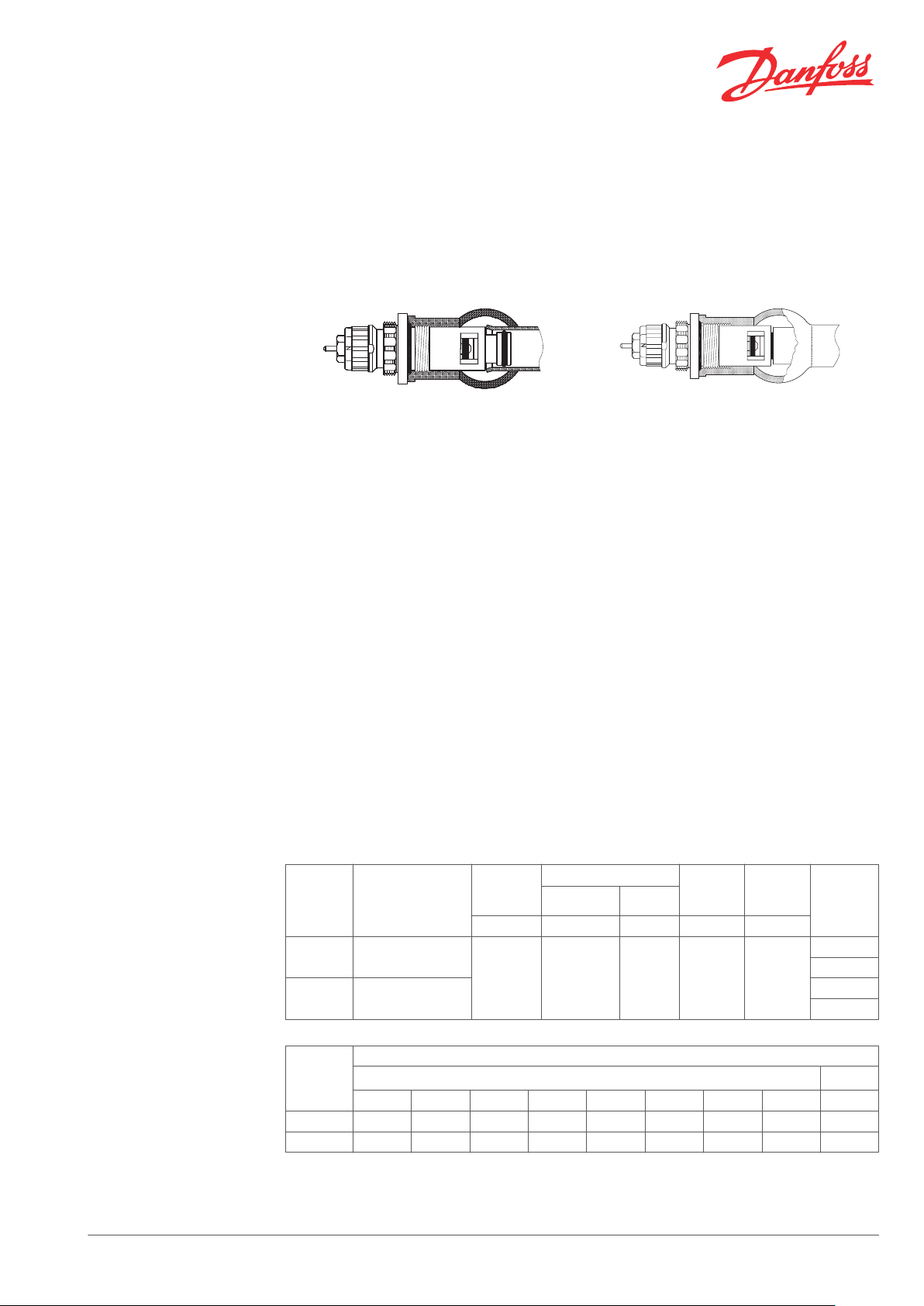
Model D Model H
RA-N 013G7370 / RA-U 013G7371 RA-N 013G7390 / RA-U 013G7391
Integrated valves types RA-N 013G7370 and RAU 013G7371, both with built-in presetting, are
designed for incorporation into valve radiators
from different radiator manufacturers.
The two valve types can be recognised by the
colour of the presetting ring:
Red: RA-N,
▪
Yellow: RA-U.
▪
Integrated valves can be used in one and two
pipe installations with circulating pump.
Integrated valves model D can be incorporated
into valve radiators from the following
manufacturers: Alarko, Arbonia, Barlo, Baufa,
Biasi, Brugman, Brötje, Buderus, Cetra, CICH,
DéLonghi (Radel), Finimetal, Hudevad, Northor,
Potterton Myson, Ribe (Rio), Schäfer, Termo
Teknik, Univa
Integrated valves types RA-N 013G7390 and RA-U
013G7391, both with built-in presetting, are
designed for incorporation into valve radiators
from different radiator manufacturers.
The two valve types can be recognised by the
colour of the presetting ring:
Red: RA-N,
▪
Yellow: RA-U.
▪
Integrated valves can be used in one and two
pipe installations with circulating pump.
Integrated valves model H can be incorporated
into valve radiators from the following
manufacturers: Agis, DEF, Dianorm (Germany),
Eleks (Elba or ECA), Ferroli IMA, Henrad, Kaimann,
Korado, Manaut, Radson, Rettig (Purmo), Rettig
Silesia, Reusch, Stelrad, Superia, Türk Demir,
Vasco, VEHA, VSZ Korad, Zenith
Code Nos. and Technical
Data
Danfoss Heating Solutions VDVEO302 © Danfoss 03/2011 1
Type
RA-N G ½ A
RA-U G ½ A
Type
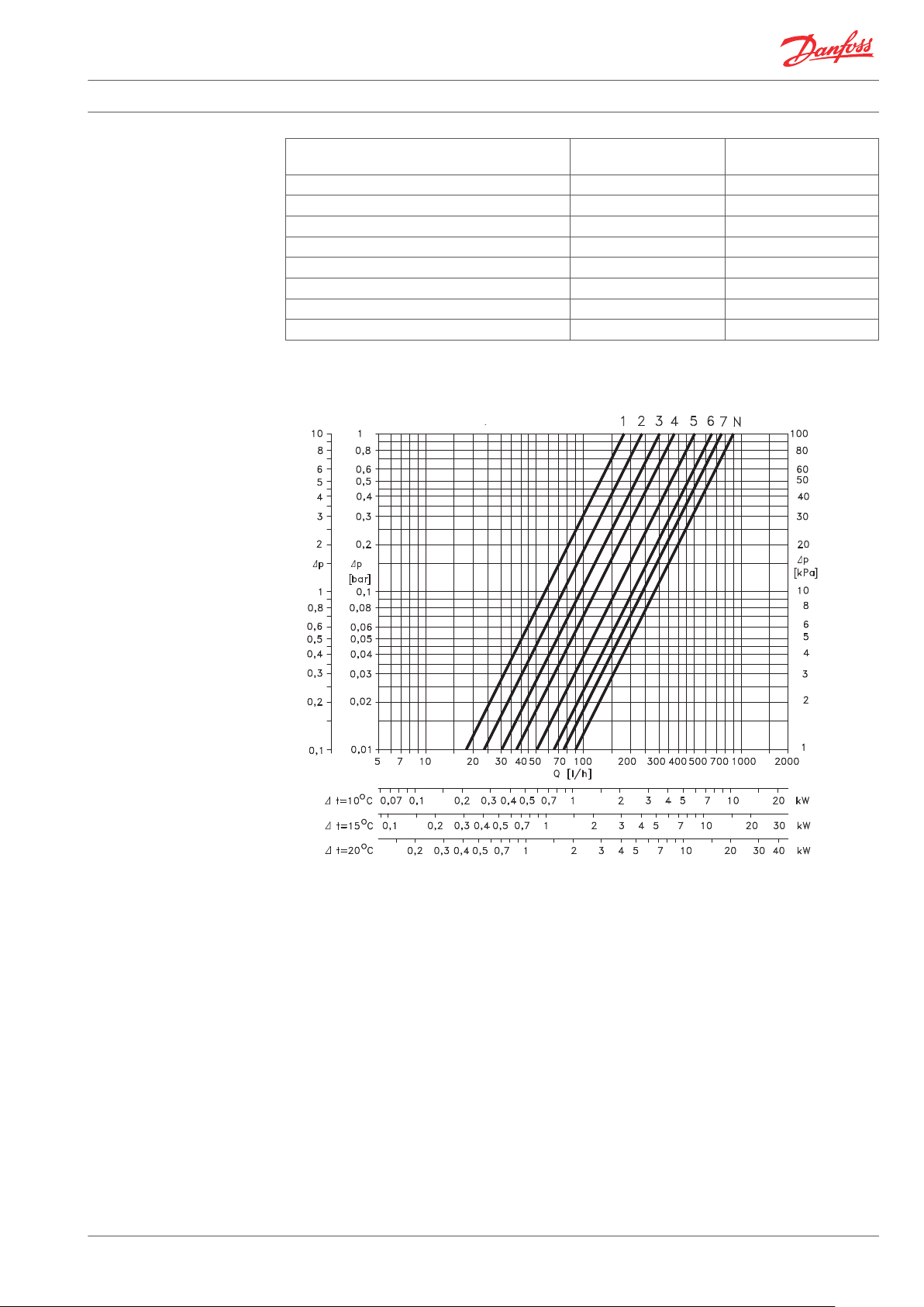
RA-N 0.14 0.21 0.26 0.32 0.46 0.59 0.73 0.87 1.05
RA-U 0.04 0.05 0.07 0.09 0.13 0.18 0.24 0.34 0.55
Connection
thread
1 2 3 4 5 6 7 N N
Max.
water
temp.
120 0.05-0.2 0.6 16 10
Differential pressure
Rec. Tech
°C bar bar bar bar
Presetting
kv-value
2) 3)
1)
Test
press.
Work.
press.
Code no.
013G7370
013G7390
013G7371
013G7391
k
vs
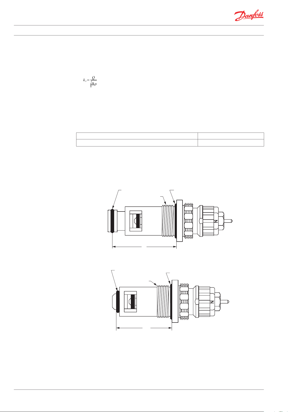
Ø12.42 x 1.78
Ø18.4 x 2.7
G 1/2”
41
Ø8.5 x 2.5
Ø18.4 x 2.7
G 1/2”
35.5
Data Sheet Integrated Valves Series 3, Model D & H for RA-N 013G7370-90 and RA-U 013G7371-91
1)
The technical differential pressure indicates the upper limit for a proper valve function. In most twopipe systems the recommended differential pressure is sufficient. In order to achieve a noiseless
function we recommend in smaller systems to apply automatic bypass valves or automatic balancing
valves. If pump differential pressure exceeds the recommended max. valve differential pressure it is
recommended that an automatic balancing valve type ASV-P/PV is added to the system.
2)
The kv-values indicate the flow volume (Q) in m³/h at a pressure loss (∆p) across the valve of 1 bar;
. At setting N, the kv-value in accordance with EN 215 can be stated as Xp = 2 K. At lower preset
values, Xp will be reduced until approximately Xp 0.5 at presetting 1. The table shows the average
measured values for integrated valves with radiator. The kvs-values indicate the valve capacity, when
the valve is fully open.
3)
When using a liquid filled radiator thermostat e.g. RAW, RAS-D or remote setting element type RA 5060
Xp will be increased by factor 1.6 (at setting “N”, ref. EN 215).
Spare Parts and Accessories
Design and Dimensions
Product Code no.
Gland seal, 10 pcs.
1)
The gland seal of the valve can be replaced under pressure, i.e. while the installation is in operation.
1)
013G0290
Model D – RA-N 013G7370 / RA-U 013G7371
Model H – RA-N 013G7390 / RA-U 013G7391
Danfoss standard sensor elements type RA 2000,
type RAE and type RAW are compatible with
2 VDVEO302 © Danfoss 03/2011 Danfoss Heating Solutions
Danfoss integrated valves.
Also Danfoss thermohydraulic motors type ABNM
are compatible with integrated valves.
[mwg]
Data Sheet Integrated Valves Series 3, Model D & H for RA-N 013G7370-90 and RA-U 013G7371-91
Materials
Capacities
Part RA-N 013G7370
RA-N 013G7390
Valve housing Ms 58 Ms 58
Valve seat Ms 58 Ms 58
Throttle nozzle PPS PPS
Setting dial Plastic Plastic
O-rings NBR / EPDM NBR / EPDM
Valve spindle PPS Ms 58
Valve cone NBR NBR
Pressure pin and valve spring Chrome steel Chrome steel
RA-N 013G7370 / 013G7390
RA-U 013G7371
RA-U 013G7391
Danfoss Heating Solutions VDVEO302 © Danfoss 03/2011 3

[mwg]
3
1
2
3
Data Sheet Integrated Valves Series 3, Model D & H for RA-N 013G7370-90 and RA-U 013G7371-91
RA-U 013G7371 / 013G7391
Presetting
Capacities at Xp = 2K with Danfoss radiator thermostat RA 2000 are measured without radiator and
connection fittings.
1. Presetting range
2. Factory setting and one-pipe system
3. Reference mark
Presetting can be selected infinitely variably
within the range of 1 to 7. At setting ‘N’ the valve
is fully open. Setting in the shaded areas of the
drawing should be avoided.
The presetting values of the integrated valve can
be adjusted easily and accurately without the use
of tools (factory setting: N):
When the radiator thermostat has been installed,
the presetting is protected against unintended
regulation.
Remove the protective cap or the sensor
▪
Find the reference mark
▪
Turn the setting ring until the chosen
▪
presetting aligns with the reference mark
The presetting is controlled directly without the
In a one-pipe installation, the setting ‘N’ must be
used. Setting ‘N’ can be used as a flushing
position if the system has to be flushed out
because of dirt problems.
use of equipment. After installation in the
radiator, the reference mark of the valves will not
always be positioned in the same place.
4 VDVEO302 © Danfoss 03/2011 Danfoss Heating Solutions

± 5°
1
3
4
5
2
10 mm
KW 17
Data Sheet Integrated Valves Series 3, Model D & H for RA-N 013G7370-90 and RA-U 013G7371-91
Mounting Instructions
Installation of an integrated valve at radiator
manufacturer’s plant
An integrated valve can only be fitted once in a
radiator (because of the load on the deformation
zone).
Fit the integrated valve in the radiator using
▪
a 12-edge spanner, KW 21.
Tighten using a torque of 30-35 Nm
▪
If required, continue turning until one of the
▪
cap thread beads points upwards (only
clockwise). Tolerance for adjustment: ±5°.
Removal and fitting in an existing radiator
1. Two O-rings
2. Reference mark
Before removal: Notice the presetting value.
▪
Please mark off the valve position on the
▪
valve and the radiator (3), e.g. on top (4)
Remove valve.
▪
Fitting: Insert the integrated valve, tighten
▪
until the marked-off position has been
reached.
Setting ring with presetting numbers (5):
Red: RA-N
▪
Yellow: RA-U
▪
Replacing the Gland Seal
While the system is in operation, the gland seal can be replaced by means of a spanner, KW 10. Hold
the setting ring using a 12-edge ring-spanner, KW 17.
Firmly
Danfoss Heating Solutions VDVEO302 © Danfoss 03/2011 5

Data Sheet Integrated Valves Series 3, Model D & H for RA-N 013G7370-90 and RA-U 013G7371-91
6 VDVEO302 © Danfoss 03/2011 Danfoss Heating Solutions

Data Sheet Integrated Valves Series 3, Model D & H for RA-N 013G7370-90 and RA-U 013G7371-91
Danfoss Heating Solutions VDVEO302 © Danfoss 03/2011 7

Data Sheet Integrated Valves Series 3, Model D & H for RA-N 013G7370-90 and RA-U 013G7371-91
Danfoss A/S
Heating Solutions
Haarupvaenget 11
8600 Silkeborg
Denmark
Phone:+45 7488 8000
Fax: +45 7488 8100
Email: heating.solutions@danfoss.com
www.heating.danfoss.com
Danfoss can accept no responsibility for possible errors in catalogues, brochures and other printed material. Danfoss reserves the right to alter its products without notice. This also applies to products
already on order provided that such alterations can be made without subsequential changes being necessary in specifications already agreed. All trademarks in this material are property of the respective
companies. Danfoss and the Danfoss logotype are trademarks of Danfoss A/S. All rights reserved.
8 VDVEO302 © Danfoss 03/2011 Danfoss Heating Solutions
 Loading...