

Page 1
3
1
2
3
Data Sheet
Integrated Service and Replacement Valve with
Presetting Feature - 013G7315
Application
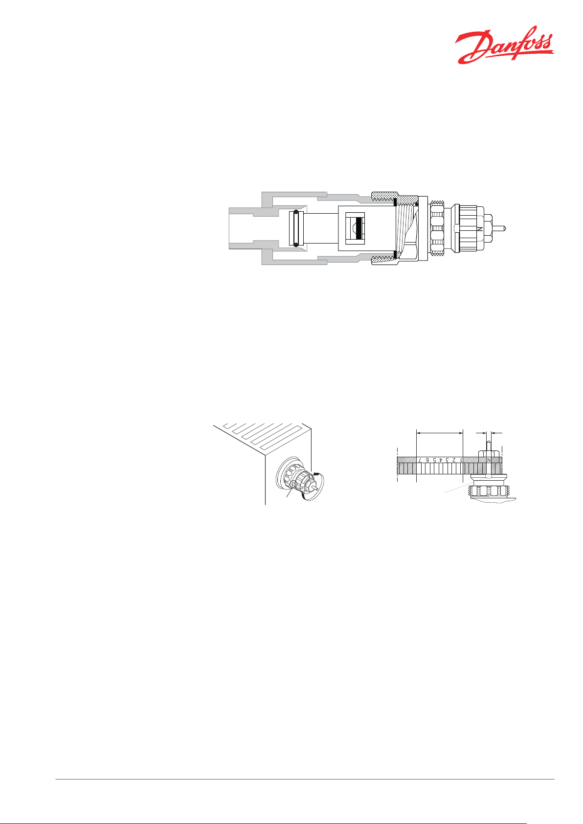
Presetting
The integrated service and replacement valve
type RA-N 013G7315 with built-in presetting is
designed for incorporation into older valve radiators from different radiator manufacturers.
The integrated valve can be used in one- and
two-pipe installations with circulating pump.
The gland seal of the valve can be replaced while
the system is in operation.
1. Presetting range
2. Factory setting and one-pipe system
3. Reference mark
The presetting values of the integrated valve can
be adjusted easily and accurately without the use
of tools (factory setting: N):
To avoid calcification and corrosion, it is important for the composition of the circulating water
to comply with the VDI 2035 guidelines.
Danfoss thermostatic sensors type RA 2000, RAE
and RAW with patented snap sockets as well as
Danfoss thermo-hydraulic actuators TWA can be
installed directly onto the integrated valve.
In a one-pipe installation, the setting ‘N’ must be
used.
Setting ‘N’ can also be used for flushing the system to solve dirt problems.
Setting in the shaded areas of the drawing above
is not recommendable and should be avoided.
Remove the protective cap or the thermo-
▪
static sensor
Find the reference mark
▪
Turn the setting ring until the chosen pre-
▪
setting aligns with the reference mark
The presetting is controlled directly without the
use of any equipment. After installation in the radiator, the reference mark of the valve will not always be positioned in the same place.
Presetting can be selected infinitely variably
Danfoss Heating Solutions VDTVC402 © Danfoss 05/2013 1
within the range of 1 to 7. At setting ‘N’ the valve
is fully open.
When a thermostatic sensor has been installed
onto the valve, the presetting is protected
against unintended regulation.
For Danfoss elements RA 2000, RAE and RAW a
theft protection device is available. This device
also provides added security against unwanted
adjustment of the preset values.
Page 2
Data Sheet Integrated Service and Replacement Valve with Presetting Feature - 013G7315
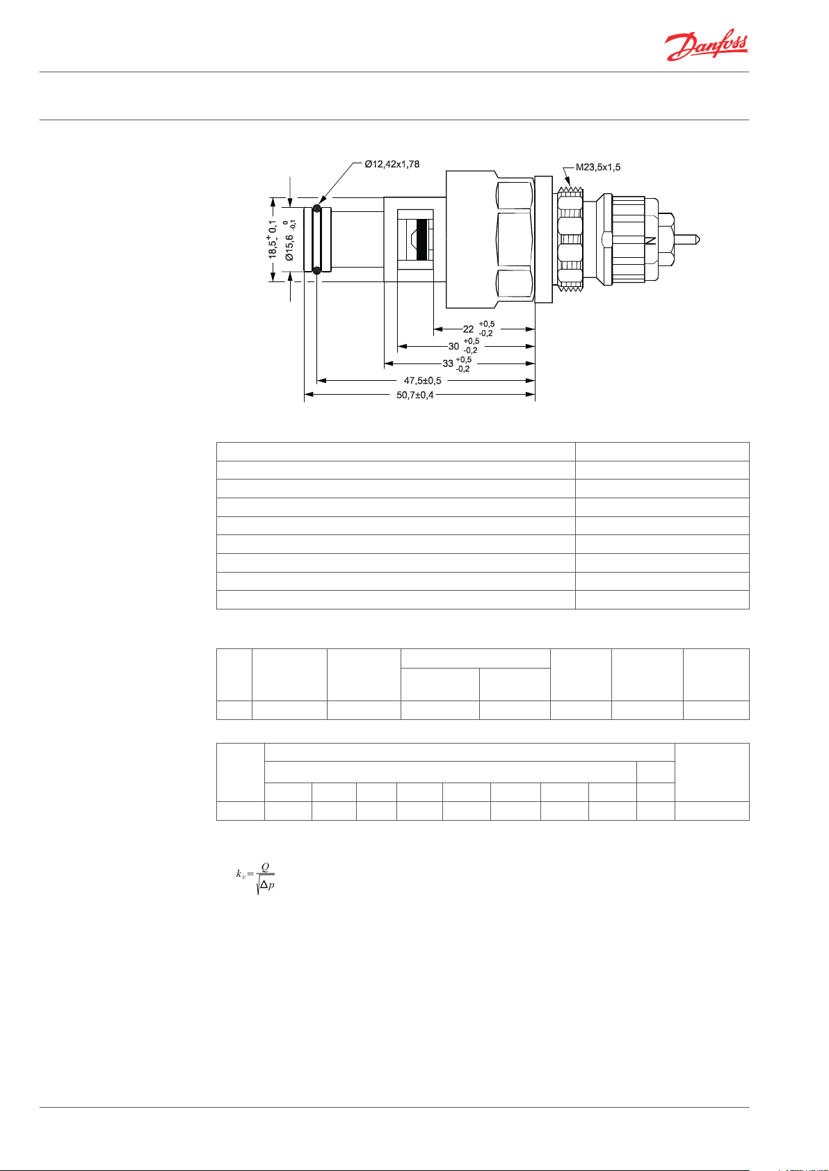
Design and Dimensions
Materials
Technical Data
Valve housing Ms 58
Valve seat Ms 58
Throttle nozzle PPS
Setting dial Plastic
O-rings NBR / EPDM
Valve spindle PPS
Valve cone NBR
Pressure pin and valve spring Chrome steel
Adapter Ms 58
3)
technical,
bar
Test pres-
sure, bar
Working
pressure,
bar
Code no.
Type
Connection
thread
Max. water
temp., °C
Differential pressure
recommen-
ded, bar
RA-N G ¾ A 120 0.05 - 0.2 0.6 16 10 013G7315
Presetting
Type
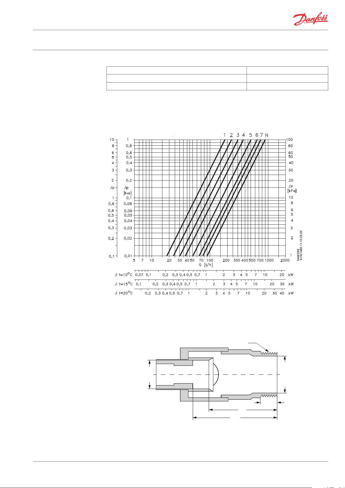
kv-value
1) 2)
k
Code no.
vs
1 2 3 4 5 6 7 N N
RA-N 0.14 0.21 0.26 0.32 0.46 0.59 0.73 0.87 1.05 013G7315
1)
The kv-values indicate the flow volume (Q) in m³/h at a pressure loss (∆p) across the valve of 1 bar.
. At setting N the kv-value in accordance with EN 215-1 can be stated as Xp = 2 K. At lower preset
values, Xp will be reduced until approximately Xp 0.5 at presetting 1. The table shows the average measured values for integrated valves with radiator. The kvs-values indicate the valve capacity, when the
valve is fully open.
2)
When using a liquid filled thermostatic sensor (e.g. RAE, RAW, RAS-D or remote setting element type RA
5060), Xp will be increased by factor 1.6 (at setting “N”, ref. EN 215).
3)
The technical differential pressure indicates the upper limit for a proper valve function. In most twopipe systems the recommended differential pressure is sufficient. In order to achieve a noiseless function we recommend in smaller systems to apply automatic bypass valves or automatic balancing
valves. If pump differential pressure exceeds the recommended max. valve differential pressure it is recommended that an automatic balancing valve type ASV-P/PV is added to the system.
2 VDTVC402 © Danfoss 05/2013 Danfoss Heating Solutions
Page 3
47.5
Ø16H8
38.5
min. 8
Ø20.75 ± 0.25
G 3/4
(ISO 228)
Data Sheet Integrated Service and Replacement Valve with Presetting Feature - 013G7315
Spare Parts and Accessories
Capacities
Product Code no.
Gland seal, 10 pcs.
1)
013G0290
Red protection cap 013G0951
1)
The gland seal of the valve can be replaced under pressure, i.e. while the installation is in operation.
RA-N 013G7315
Capacities at Xp = 2K with Danfoss radiator thermostats RA 2000 are measured without radiator and connection fittings.
Dimensions
Standard fittings
The dimensions stated may vary according to different radiator manufacturers. (
013M5058 E0002 001 047 97.03.25)
Danfoss Heating Solutions VDTVC402 © Danfoss 05/2013 3
Page 4

1
30 + 5 Nm
2
10 mm
KW 17
Data Sheet Integrated Service and Replacement Valve with Presetting Feature - 013G7315
Mounting Instructions
Replacing the Gland Seal
Installation of an integrated valve at radiator
manufacturer’s plant
Fit the integrated valve in the radiator using
▪
a 12-edge spanner, KW 21.
Tighten using a torque of 30 Nm + 5 Nm.
▪
If required, continue turning until one of the
▪
cap thread beads (1) points upwards (2). Tolerance for adjustment: ±5°.
Removal and fitting in an existing radiator
Before removal: Notice the presetting value.
▪
Please mark off the valve position on the
▪
valve and the radiator, e.g. on top.
Remove valve.
▪
Fitting: Insert the integrated valve, tighten
▪
until the marked-off position has been
reached.
Firmly
While the system is in operation, the gland seal
can be replaced by means of a spanner, KW 10.
Press the pin firmly to ensure contact with the
valve spindle.
Hold the setting ring using a 12-edge ring-spanner, KW 17.
Danfoss A/S
Heating Solutions
Haarupvaenget 11
8600 Silkeborg
Denmark
Phone: +45 7488 8000
Fax: +45 7488 8100
Email: heating.solutions@danfoss.com
www.heating.danfoss.com
Danfoss can accept no responsibility for possible errors in catalogues, brochures and other printed material. Danfoss reserves the right to alter its products without notice. This also applies to products
already on order provided that such alterations can be made without subsequential changes being necessary in specifications already agreed. All trademarks in this material are property of the respective
companies. Danfoss Heating Solutions and the Danfoss Heating Solutions logotype are trademarks of Danfoss A/S. All rights reserved.
4 VDTVC402 © Danfoss 05/2013 Danfoss Heating Solutions
 Loading...