

Page 1
Data Sheet
Integrated Presetting Valve, Type RA-N 013G3259 with Soldering Connection
Application
Code Nos. and Technical
Data
The valve is specially intended and designed to
be built in the radiator by the radiator
manufacturer.
The valve body RA-N is used in two-pipe district
or central heating systems with pump, or in onepipe pumped systems.
RA-N is fitted with built-in presetting of max.
water flow within the setting range:
kv = 0.16 - 1.00 m³/h
Danfoss thermostatic sensors type RA 2000 and
RAW with patented snap sockets as well as
Danfoss thermo-hydraulic actuators can be
installed directly onto the integrated valve.
Solder
Type
RA-N,
angle
connection
In, ØmmOut, Ø
mm
15 15 0.16 0.20 0.25 0.35 0.47 0.60 0.73 0.80 1.00 120 013G3259
1)
1 2 3 4 5 6 7 N N °C
kv-value
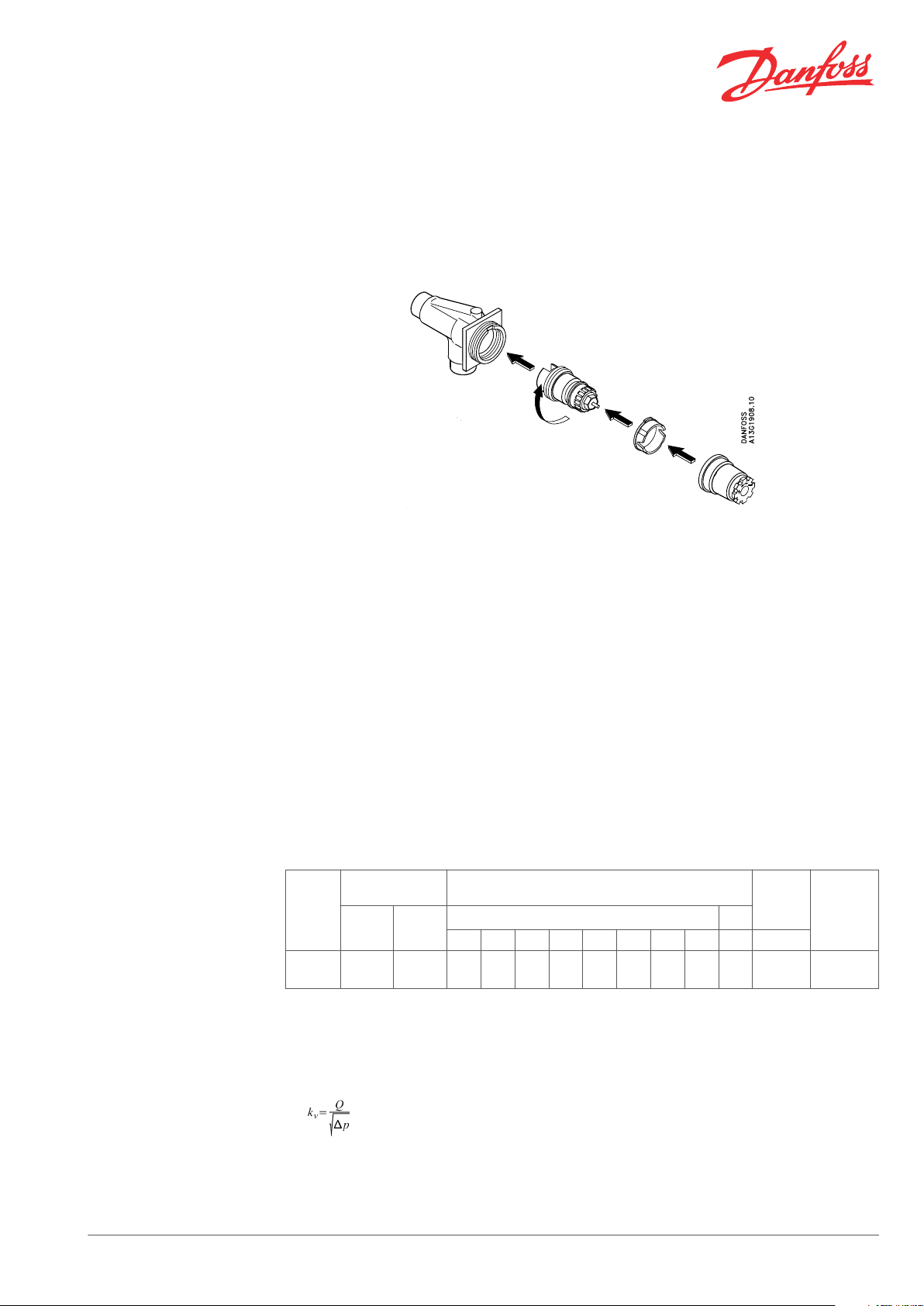
The valve is supplied unassembled in five main
groups: valve body, valve top assembly, valve
insert, protective cap, and rotation lock.
The valve body is made of MS 58 brass.
In order to avoid deposition and corrosion, the
composition of the hot water must be in
accordance with the VDI 2035 guideline (Verein
Deutscher Ingenieure).
Presetting
2) 3)
Max.
water
temp.
k
vs
Code no.
Pressure data: Differential pressure 4): 0.6 bar, max. working pressure: 10 bar, test pressure: 16 bar.
1)
Inlet and outlet socket prepared for soldering of pipes.
2)
The kv-values indicate the flow volume (Q) in m³/h at a pressure loss (∆p) across the valve of 1 bar;
. At setting N, the kv-value in accordance with EN 215 can be stated as Xp = 2 K. At lower preset
values, Xp will be reduced until approximately Xp 0.5 at presetting 1. The table shows the average
measured values for integrated valves with radiator. The kvs-values indicate the valve capacity, when
the valve is fully open.
Danfoss Heating Solutions VD34A302 © Danfoss 03/2011 1
Page 2
Data Sheet Integrated Presetting Valve, Type RA-N 013G3259 - with Soldering Connection
3)
When using a liquid filled radiator thermostat e.g. RAW, RAS-D or remote setting element type RA 5060
Xp will be increased by factor 1.6 (at setting “N”, ref. EN 215).
4)
The technical differential pressure indicates the upper limit for a proper valve function. In most twopipe systems the recommended differential pressure is sufficient. In order to achieve a noiseless
function we recommend in smaller systems to apply automatic bypass valves or automatic balancing
valves. If pump differential pressure exceeds the recommended max. valve differential pressure it is
recommended that an automatic balancing valve type ASV-P/PV is added to the system.
Spare Parts and Accessories
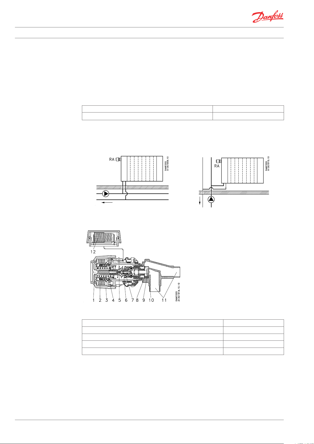
System
Design
Product Code no.
Gland seal, 10 pcs.
1)
The gland seal of the valve can be replaced under pressure, i.e. while the installation is in operation.
1)
013G0290
1. Condensate
2. Bellows
3. Setting dial
4. Setting spring
5. Limitation pin
6. Pressure pin
7. O-ring seal
8. Throttle nozzle
9. Valve cone
10. Valve body
11. Soldering connections
12. Remote sensor
Materials in contact with water
Valve body and other metal parts Ms 58 brass
Throttle nozzle PPS
O-ring EPDM
Valve cone NBR
Pressure pin in gland seal Chrome steel
2 VD34A302 © Danfoss 03/2011 Danfoss Heating Solutions
Page 3
3
1
2
3
Data Sheet Integrated Presetting Valve, Type RA-N 013G3259 - with Soldering Connection
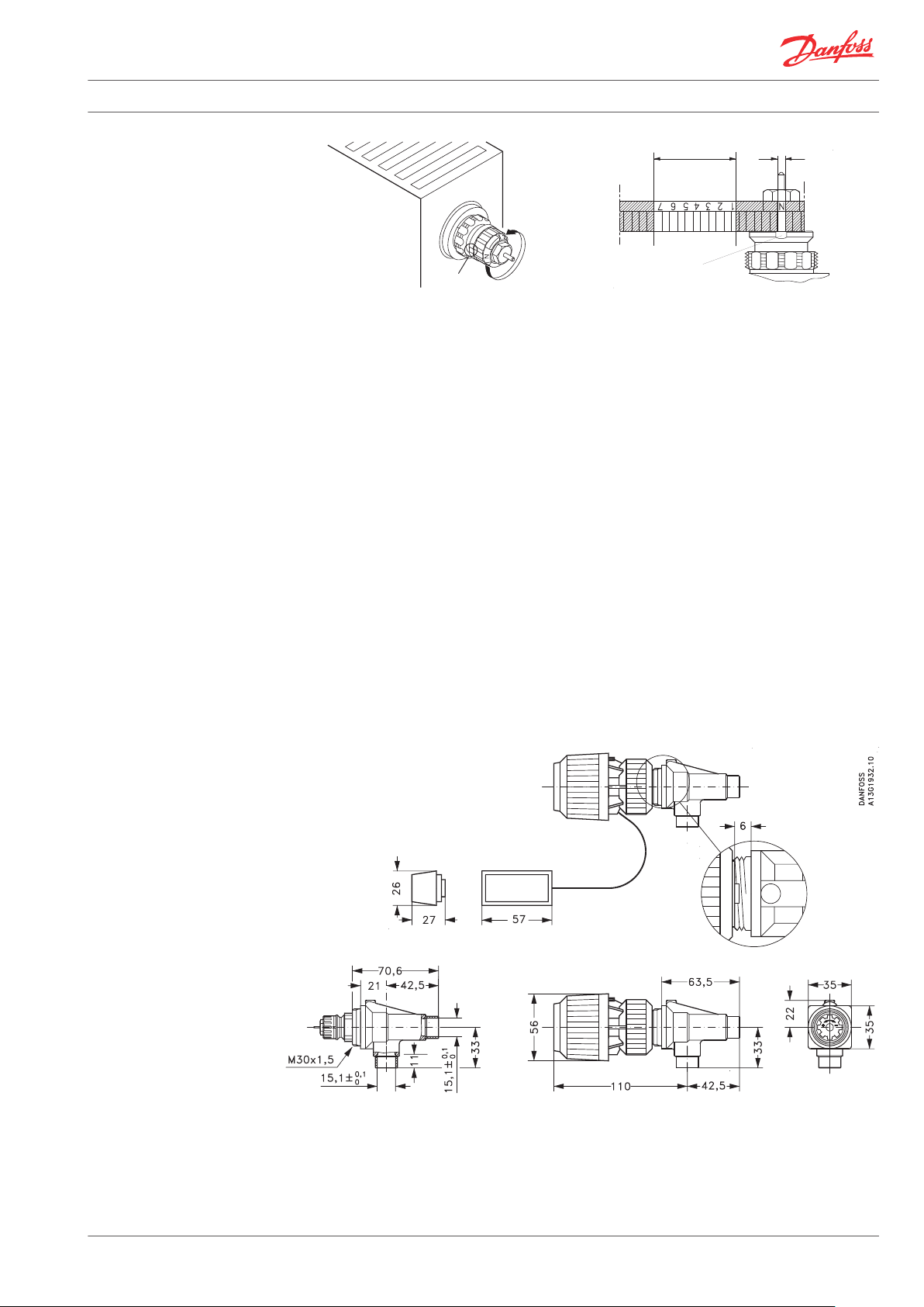
Presetting
Dimensions
1. Presetting range
2. Factory setting and one-pipe system
3. Reference mark
The presetting values of the integrated valves
can be adjusted easily and accurately without the
use of tools (factory setting: ‘N’):
Remove the protective cap or the
▪
thermostatic sensor
Find the reference mark
▪
Turn the setting ring until the desired
▪
presetting aligns with the reference mark.
The presetting is controlled directly without the
use of equipment. After installation in the
radiator, the reference mark of the valves will not
always be positioned in the same place.
Presetting can be selected infinitely variably
within the range of 1 to 7. At setting ‘N’ the valve
is fully open. Setting in the shaded areas of the
drawing should be avoided.
In a one-pipe installation, the setting ‘N’ must be
used.
Setting ‘N’ can be used as a flushing position if
the system has to be flushed out because of dirt
problems.
When the radiator thermostat has been installed,
the presetting is protected against unintended
regulation.
For Danfoss elements RA 2000, RAS-C, RAS-D and
RAE, a theft protection device is available; this
also provides added security against unwanted
adjustment of the preset values.
Danfoss Heating Solutions VD34A302 © Danfoss 03/2011 3
Page 4

Data Sheet Integrated Presetting Valve, Type RA-N 013G3259 - with Soldering Connection
Capacities
RA – capacities with P-band between 0.5 K and 2 K
Sizing Example
Mounting of Thermostatic
Sensor
Known values
Heat demand: ф = 1500 kcal/h
System temperature drop: ∆t = 20 °C
Differential pressure: ∆p = 0.10 bar
Calculation
Water quantity:
The valve body is designed for mounting in the
inlet of the radiator observing the direction of the
flow arrow.
The setting is found in the capacity diagramme
above: Presetting 3.
If the sizing point found is between two settings,
the highest setting is chosen.
Alternatively, the settings can be found directly
in the table “Ordering and specifications”.
When using a built-in sensor, the valve body
should be mounted with the gland seal
horizontal.
4 VD34A302 © Danfoss 03/2011 Danfoss Heating Solutions
Page 5

10 mm
KW 17
Data Sheet Integrated Presetting Valve, Type RA-N 013G3259 - with Soldering Connection
Replacement of the Gland
Seal
During the construction period, before the sensor
is mounted, the heating can be manually
regulated by means of the protective cap on the
valve body.
An open-end spanner is used for mounting the
sensor onto the valve body.
While the system is in operation, the gland seal
can be replaced by means of a spanner, KW 10.
Instructions for installation are enclosed.
The sensor should always be placed where the
room air can circulate freely around it.
Firmly
After mounting the gland seal, press pin firmly to
ensure proper contact to the valve spindle.
Hold the setting ring using a 12-edge ring
spanner, KW 17.
Danfoss Heating Solutions VD34A302 © Danfoss 03/2011 5
Page 6

Data Sheet Integrated Presetting Valve, Type RA-N 013G3259 - with Soldering Connection
6 VD34A302 © Danfoss 03/2011 Danfoss Heating Solutions
Page 7

Data Sheet Integrated Presetting Valve, Type RA-N 013G3259 - with Soldering Connection
Danfoss Heating Solutions VD34A302 © Danfoss 03/2011 7
Page 8

Data Sheet Integrated Presetting Valve, Type RA-N 013G3259 - with Soldering Connection
Danfoss A/S
Heating Solutions
Haarupvaenget 11
8600 Silkeborg
Denmark
Phone:+45 7488 8000
Fax: +45 7488 8100
Email: heating.solutions@danfoss.com
www.heating.danfoss.com
Danfoss can accept no responsibility for possible errors in catalogues, brochures and other printed material. Danfoss reserves the right to alter its products without notice. This also applies to products
already on order provided that such alterations can be made without subsequential changes being necessary in specifications already agreed. All trademarks in this material are property of the respective
companies. Danfoss and the Danfoss logotype are trademarks of Danfoss A/S. All rights reserved.
8 VD34A302 © Danfoss 03/2011 Danfoss Heating Solutions
 Loading...