

Data Sheet
Integrated High Capacity Valve, Type RA-G
013G8670
Application
Code Nos. and Technical
Data
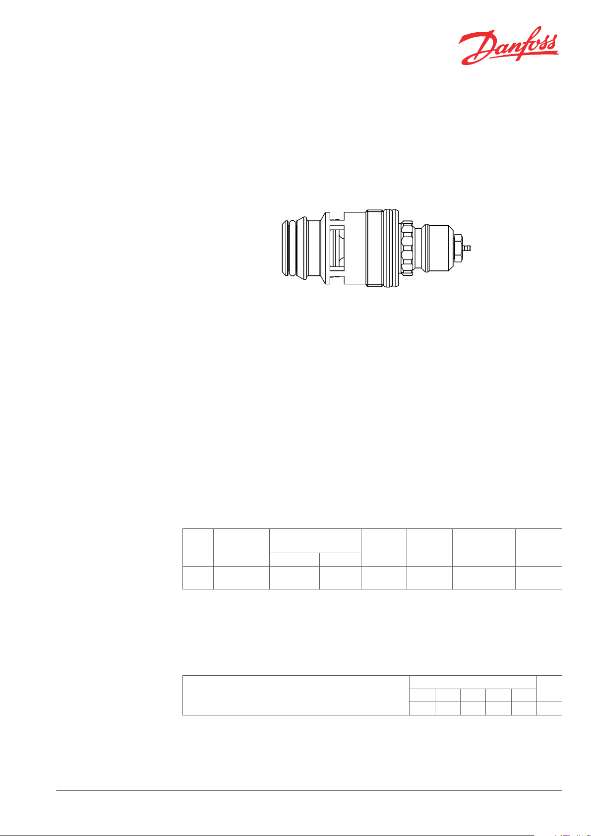
The integrated high capacity valve, type RA-G
013G8670, is designed for incorporation into
convectors from different radiator manufacturers.
All thermostatic sensors in the RA series can be
combined with RA-G 013G8670.
Danfoss thermostatic sensors types RA2000, code
no. 013G2973 and 013G2974, can be installed
directly onto the integrated valve.
For easy identification the protective cap is grey.
The valves are nickel plated.
Type
RA-G
BIV
1)
Sensor
connection
RA 2000
The maximum differential pressure specified is the maximum pressure at which the valves give
satisfactory regulation. As with any device which imposes a pressure drop in the system, noise may
occur under certain flow/pressure conditions. To ensure quiet operation, maximum pressure drop
should not exceed 30 to 35 kPa. The differential pressure can be reduced by the use of the Danfoss
differential pressure regulators.
Differerential
pressure
Recomm. Technical
0.05 - 0.1
bar
1)
0.15 bar 16 bar 10 bar 120˚ C 013G8670
The integrated valves have a reinforced stuffing
box to avoid damage on the valve at low
temperatures.
The gland seal of the valve can be replaced while
the system is in operation.
In order to avoid deposition and corrosion the
composition of the hot water must be in
accordance with the VDI 2035 guideline (Verein
Deutscher Ingenieure).
Test
pressure
Work.
pressure
Max. water
temperature
Code no.
P-band (K)
RA-G BIV 013G8670, kv-value2), (m3/h at ∆p =1 bar)
Danfoss Heating Solutions VDFOE102 © Danfoss 02/2011 1
0.5 1 1.5 2.0 3.0
0.54 1.07 1.57 2.01 2.66 3.50
k
vs
A
30°
±
5°
60°
±
5°
(Ø
)15
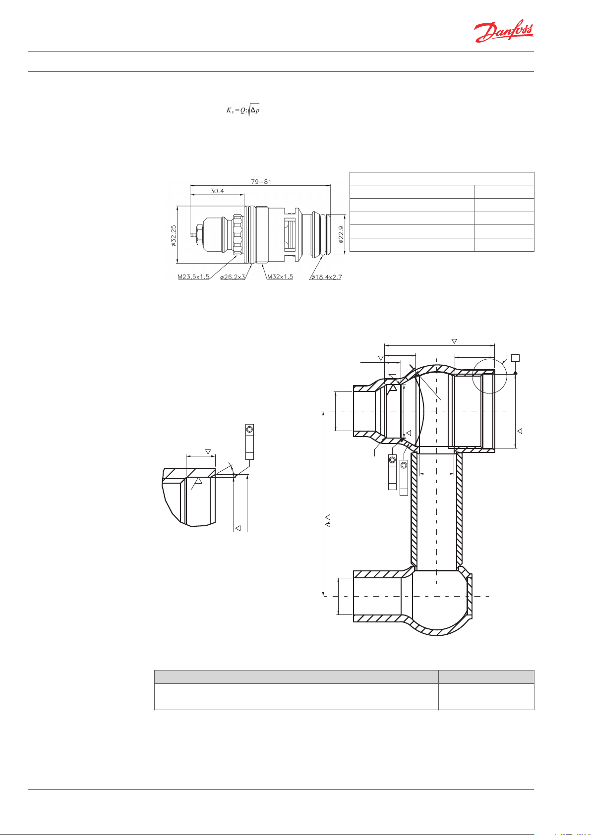
14 +1
M x1,5 - 6H32
min. 2 mm.
13,5±0,2
80
±
0,5
Ø
16
±
0,5
Ø
33,5
±
0,15
Ø
32,5
±
0,06
5
+0,1
0
47,5±0,3
7±0,2
Ø
23,06
±
0,06
A
Ø
17
±
0,3
SEE DETAIL A
R0.8
Ø
0,3
Ø
0,3 A
DETAIL A
SCALE 5:1
Ø
0,2 A
3.2
1
3.2
Data Sheet Integrated High Capacity Valve, Type RA-G 013G8670
2)
The kv-value indicates the flow volume (Q) in m3/h at a given lift and a pressure drop (p) across the
valve at 1 bar. . The kvs-value states the flow Q at a maximum lift, i.e. at fully open valve. If a
remote temperature adjuster is used, the P-band is increased by a factor of 1.1. If an RTS sensor is
used, the P-band is increased by a factor of 1.2.
Design and Dimensions
Radiator Dimensions
Materials in contact with water
Valve housing Ms 58
Valve seat Ms 58
O-ring NBR / EPDM
Valve cone NBR
Pressure pin and valve spring Chrome steel
Spare Parts and
Accessories
2 VDFOE102 © Danfoss 02/2011 Danfoss Heating Solutions
Product Code no.
Gland seal, 10 pcs. 013L0669
Black protection cap 013G8439

Data Sheet Integrated High Capacity Valve, Type RA-G 013G8670
Capacities
013G8670
Danfoss Heating Solutions VDFOE102 © Danfoss 02/2011 3

Data Sheet Integrated High Capacity Valve, Type RA-G 013G8670
Danfoss A/S
Heating Solutions
Haarupvaenget 11
8600 Silkeborg
Denmark
Phone:+45 7488 8000
Fax: +45 7488 8100
Email: heating.solutions@danfoss.com
www.heating.danfoss.com
Danfoss can accept no responsibility for possible errors in catalogues, brochures and other printed material. Danfoss reserves the right to alter its products without notice. This also applies to products
already on order provided that such alterations can be made without subsequential changes being necessary in specifications already agreed. All trademarks in this material are property of the respective
companies. Danfoss and the Danfoss logotype are trademarks of Danfoss A/S. All rights reserved.
4 VDFOE102 © Danfoss 02/2011 Danfoss Heating Solutions
 Loading...