

Page 1
Data Sheet
High capacity valve body, type RA-G
Application
Quality
Systems
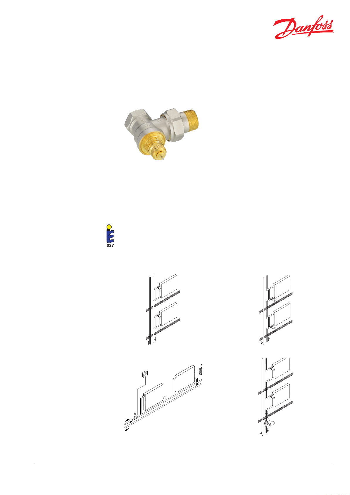
The high capacity valves, type RA-G, are primarily
used in one-pipe systems.
All RA-G valves can be combined with all thermostatic sensors in the RA-series.
All Danfoss RA-G high capacity valves are
manufactured to the highest standards, and
are approved to the European Standard EN
215.
The RA-G valves are tted with a grey protective
cap. This protective cap must not be used as a
manual shut o device. A special manual shut o
device is available (code no. 013G3300).
The pressure pin in the gland seal is of chromium
steel and works in a lifetime lubricated O-ring. The
complete gland seal assembly can be replaced
without draining the system.
In order to avoid depositions and corrosion the
composition of the hot water must be in accordance with the VDI 2035 Guidelines.
It is recommended that formulations containing
mineral oil are avoided.
1. One-pipe system, ow from top 2. One-pipe system, ow from bottom
3. Zone control application. Thermal actuator TWA
in combination with room thermostat/programmer.
VDSXR102 © Danfoss 11/2010
4. Danfoss Renovation+ with AB-QM and AB-QT
1
Page 2
Data Sheet High capacity valve body, type RA-G
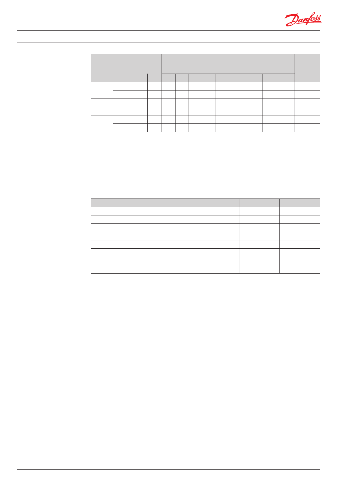
Ordering
Accessories
Max
ow
temp.
Code no.
Typ e Design
Connection kv-values [m3/h] P-Band [K]
1)2)
Max. pressure
[bar]
In Out 0.5 1.0 1. 5 2.0 kvsWork. Di.3)Tes t °C
RA -G 15
RA-G 20
RA-G 25
1)
The kv-value indicates the water ow (Q) in m3/h at a pressure drop (∆p) across the valve of 1 bar. kv = V : √∆p.
The kvs-values state the ow (Q) at a maximum lift, i.e. at fully open valve.
2)
If a RAW/RAS-C/RAS-C2/RAS- D/RAX/RAE sensor or a remote sensor is used the P-band is extended by a factor 1.6.
3)
Working pressure = static + dierential pressure. The maximum dierential pressure specied is the maximum pressure
Angle Rp ½ R ½ 0.54 1.07 1.61 2.06 4.30 16 0.20 25 120 013G1676
Straight Rp ½ R ½ 0.51 0.94 1.35 1.63 2.30 16 0.20 25 120 013 G1675
Angle Rp / R / 0.57 1.11 1.16 2.20 5. 01 16 0.20 25 12 0 013G1678
Straight Rp / R / 0.54 1.07 1.61 2.06 3. 81 16 0.20 25 120 013G1677
Angle R
Straight R
R 1 0.59 1. 27 1.77 2 .41 5.50 16 0.16 25 120 013G16 80
p 1
R 1 0.57 1.16 1.71 2.27 4.58 16 0.16 25 120 013G1679
p 1
at which the valves give satisfactory regulation. As with any device which imposes a pressure drop in the system, noise
may occur under certain ow/pressure conditions. To ensure quiet operation, maximum pressure drop should not
exceed 30 to 35 kPa. The dierential pressure can be reduced by the use of the Danfoss dierential pressure regulators.
Product Size Code no.
Gland seal, 10 pcs.
RTD-CB back-ow restrictor
RTD-CB back-ow restrictor
RTD-CB back-ow restrictor
RTD-BR bypass restrictor
RTD-BR bypass restrictor
Service insert
Service insert
1)
The gland seal may be replaced with the heating system in operation.
2)
To avoid unintended heat emission from the radiator, it is recommended to install a ow restrictor, see further details
on ow restrictors in separate data sheet.
3)
Service inserts can only be replaced without water on the system.
1)
2)
2)
2)
2)
2)
3)
3)
- 013G 0290
DN 15 013 L192 5
DN 20 013 L192 6
DN 25 013 L192 7
DN 15/10 013 L1915
DN 20/15 013L1916
DN 15/ 20 013G170 6
DN 25 013G1707
2
VDSXR102 © Danfoss 11/2010
Page 3

Data Sheet High capacity valve body, type RA-G
Φ
[W
~ 90%
[m3/h]
RA-G solution in
one pipe system
att]
Φ
0
~30% Q0 Q
Fig. 1: Radiator curve for one-pipe installation Fig. 2
Capacities
- DN 15
Because of low dT across radiator in one-pipe system, the scope for regulation of heat emission is
narrow (at radiator curve) as gure1 shows. This
means that in a one-pipe installation extra water
in addition to the sized volume does not really
lead to any extra heat transmission.
A water quantity of 30% of the previous level
means that heat emission is reduced by ~ 10%.
A reduction of 10% of the heat emission will give
no problems in practice, since radiator surfaces
are often oversized.
1. A bypass must be established (gure 2). The
size of the bypass pipe must normally be one
dimension smaller than the dimension of the
main pipe system.
2. The RA-G - with the same dimension as the
main pipe system - is then mounted at the inlet
to the radiator.
According to this rules, the ow share into the
radiator could reach 30% of the previous level
because of the high capacity of the RA-G valve.
In case the bypass has the same diameter as the
supply pipe to the radiator, it is recommended
to use ow restrictors to provide a suitable ow
share to the radiator.
Valve capacities in combination with RA-2000 thermostatic sensor.
VDSXR102 © Danfoss 11/2010
3
Page 4

Data Sheet High capacity valve body, type RA-G
Capacities
- DN 20
Capacities
- DN 25
Valve capacities in combination with RA-2000 thermostatic sensor.
Valve capacities in combination with RA-2000 thermostatic sensor.
4
VDSXR102 © Danfoss 11/2010
Page 5

Data Sheet High capacity valve body, type RA-G
1
Design
Dimensions
5
2
6
3
8 7
4 9 10
10. Nipple
Materials in contact with water
Valve body Ms 58 brass
O-Ring EPDM
Valve cone NBR
Pressure pin Chrome steel
Spindle guide Tin bronze
1. Gland seal
2. O-ring
3. Valve plate
4. Valve seat
5. Pressure pin
6. Valve spring
7. Spindle
8. Valve body
9. Union nut
Type
Connection ISO 7-1
DN D d
L
L
L
L
L
1
2
3
2
4
L
5
6
Spanner
L
7
S
S
1
2
RA-G 15 15 Rp ½ R½ 68 96 30 58 27 52 103 27 30
RA-G 20 20 Rp ¾ R ¾ 74 106 34 66 30 54 103 32 37
RA-G 25 25 Rp 1 R 1 90 126 42 78 34 57 106 41 46
VDSXR102 © Danfoss 11/2010
5
Page 6

Data Sheet High capacity valve body, type RA-G
6
VDSXR102 © Danfoss 11/2010
 Loading...