

Page 1
Installation Guide
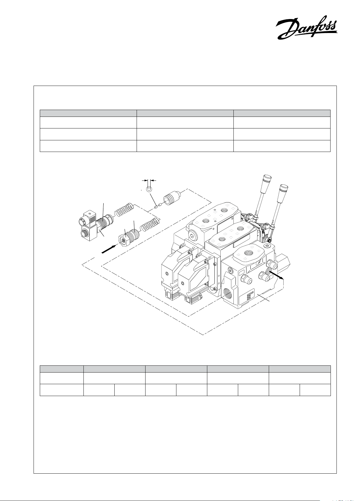
Relief valves for PVG 120
Type PVPE, PVPH
PVPE/PVH,
relief valves
155R9 957
Position Across flats Max. tightening torque
1
2
3
22 mm
[0.87 in]
36 mm
[1.42 in]
36 mm
[1.42 in]
155R9 957
5 Nm
[45 lbf·in]
85 Nm
[750 lbf·in]
85 Nm
[750 lbf·in]
PVPH and LS
connections
PVPE
LS
2 Nm
[17.5 lbf•in)
PVPH
2
1
2.5[0.098]
P
MA
S
L
PVP
V310157.A
LS
Sealing Steel washer Cupper washer Aluminium washer Cutting edge
Threads,
DS/ISO 228/1
Max. tightening
torque
© Danfoss A/S, 2014-03 520L0527 • Rev CB • Mar 2014 1
PVPH:
G 1/4
40 Nm
[350 lbf·in]
LS:
G 3/8
60 Nm
[530 lbf·in]
PVPH:
G 1/4
20 Nm
[180 lbf in]
LS:
G 3/8
35 Nm
[310 lbf·in]
PVPH:
G 1/4
30 Nm
[270 lbf in]
LS:
G 3/8
40 Nm
[350 lbf·in]
PVPH:
G 1/4
40 Nm
[350 lbf·in]
LS:
G 3/8
60 Nm
[530 lbf·in]
Page 2
PVPE,
Technical data
Max. operation pressure
Max. pressure drop a an flow of 0.20 l/min. [0.053 US gal/min]
Recommended temperature
Oil temperature (inlet temperature)
Max. coil surface temperature
Ambient temperature
Oil viscosity
Response time for pressure relief to tank 600 ms
Enclosure to. IEC 529 IP 65
Rated voltage 12 V 24 V
Max.permissible deviation from rated supply voltage ±10% ±10%
Current consumption
at rated voltage
Power consumption
Min. temperature
Max. temperature
Operating range
Min. viscosity
Max. viscosity
at 22°C [72°F] coil temperature 1.55 A 0.78 A
at 85°C [230°F] coil temperature 1.00 A 0.50 A
at 22°C [72°F] coil temperature 19 W 19 W
at 85°C [230°F] coil temperature 12 W 12 W
350 bar
[5085 psi]
1.2 bar
[17 ps i]
30 to 60°C
[86 to 140°F]
–30°C
[–22°F ]
+90°C
[+19 4° F]
155°C
[311°F]
–30 to +60°C
[–22 to +140°F]
12 to 75 mm2/s
[65 to 347 SUS]
4 mm2 /s
[39 SUS]
460 mm2/s
[2128 SUS]
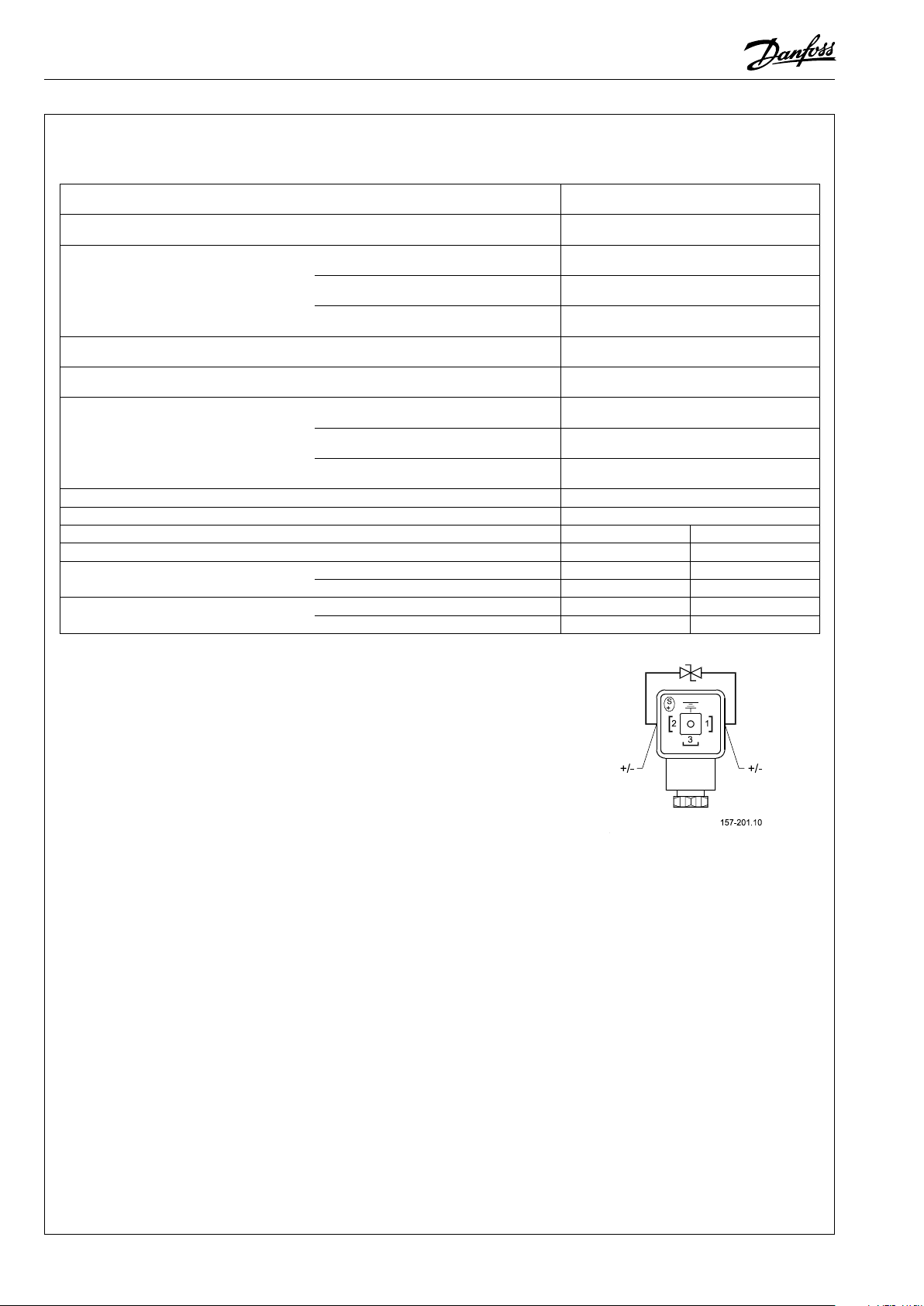
Connection PVPE
When installing the wire remember to connect the built-in diode to the plug pins.
2 520L0527 • Rev CB • Mar 2014 © Danfoss A/S, 2014-03
Page 3

Wiring example
*1
8 95743
Alarm Logic EHA
155U1805
SUPPLY: 11-30V DC
Unused inputs must
be connected to "-".
MADE IN DENMARK
10
16211
Pin no.
873,15,1651,2,14
10
22
*1
DC
U+
Prop 2
Function
Prop 1
Prop 3
N.sw.out
U-
U
PVEH
PVPE
MA
PVEH
-
+
F3
F2F1
US1UU
S2 S3
- +
+
U-U+
2
3
1
2
P
LS
P
MA
LS
PVEH
P
MA
LS
106[4.17]
PVED
117[4.61]
141[5.55]
3
1
2
3
1
2
3
1
E
-
+
U
DC
V310180.A
*1) In order not to be interpreted as defect, unused inputs must be connected to minus.
PVG 120 with normally open PVPE, PVRE remote control lever and EHA electronic alarm logic
© Danfoss A/S, 2014-03 520L0527 • Rev CB • Mar 2014 3
Page 4

4 520L0527 • Rev CB • Mar 2014 © Danfoss A/S, 2014-03
 Loading...