

Page 1
Installation Guide
PVG 16
Electrical Actuating Module PVHC
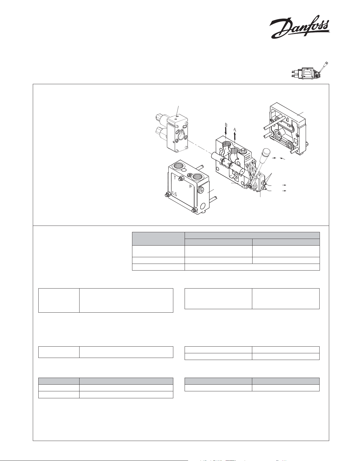
Oliestrømmens retning for
standard monterede grupper
L1407359
Oil ow direction for standard
assembled groups
Richtung des Ölstroms für
Standard-Baugruppen
Sens du débit pour ensembles
standard
Tekniske data
Technical data
Technische Daten
Caractéristiques Techniques
Parameter
Controller output
current range
Spool resistance 1.0 Ω ± 5% 0.25 Ω ± 5%
Pressure control range 5 to 15 bar [72.5 to 217.5 psi]
PVHC
P
A
7-9Nm
[61-79 lbf•in]
PVB
PVP
PVM
Q
max: P A
max: P B
Q
Control range
12 V 24 V
0 - 1200 mA 0 - 600 mA
V310175.A
L1407359
PVS
P301 776
Oil viscosity
Olieviscositet
Oil viscosity
Ölviskositet
Viscosité de huille
Range: 12 - 75 mm2/s [65 - 350 SUS]
Min.: 4 mm2/s [40 SUS]
Max.: 400 mm2/s [2130 SUS]
Filtering
Filtering in the
hydraulic system
Max. permissible degree of contamination
(ISO 4406), 1999 version): 23/19/16
Temperature
Temperatur range
Ambient Min: -30°C to 80°C [-22 to 176°F]
Pilot pressure
Pilottryk (over tanktryk)*
Pilot pressure (over tank)*
Pilotdruck (über Tank)*
Pression pilote (resérvoir)*
*Anvendes sammen med hydraulisk aktiverede glidere
* Designed t o be used with hydrauli c activated spool s
* Entworfen, um mit hydraulisch betriebenen Schieber verwendet zu werden
* Conçu pour u ne utilisation avec d es tiroirs d’acti vation hydrauliqu e
Nom: 25 bar [363 psi]
Min: 21 bar [305 psi]
Max: 25 bar [363 psi]
Max tank pressure
Port T Static 25 bar [363 psi]
Port T Dynamic 30 bar [435 psi]
Enclosure
Protection class
Deutsch DT IP 67
Medium Max: -20°C to 80°C [-4 to 176°F]
PVHC er produceret i et miljø, hvor der benyttes mineralsk hydraulikolie
The PVHC is produced in an environment using mineral based hydraulic oil
Das PVHC wird in einer mineralbasierten Hydrauliköl-Umgebung produziert
Le PVHC est fabriqué dans un environnement qui utilise de l’huile hydraulique à base minérale
© Danfoss A/S, 2014-11 L1407359 • Rev AB • Nov 2014 1
Page 2
Q
VM
Aktivering
Activation
Betätigung
Commande
Deutsch Version
U
(B)
DC
UDC (A)
P301 120
[0.28]
0.50
Parameter
12 V 24 V
Control range
Current 1 - 1200 mA 0 - 600 mA
Pressure control range 5 to 15 bar [72.5 to 217.5 psi]
[US gal/min]
L/min
1
70
60
[15]
50
40
[10]
30
20
[5]
10
3 4 5
6 7
[0.12]
[0.16] [0.2] [0.24]
0.75
1 2
0.50
[0.04]
2
1
[0.08]
[0.12]
Spool stroke, mm
6
D
1
6
C
B
A
AA
P
5
4
3
[0.16]
mm
[in]
[0.2] [0.04] [0.08]
PVE
0.25
Us/U
DC
3.75 2.50 1.25
SP V
DC
P005 598E
5
4
3
2
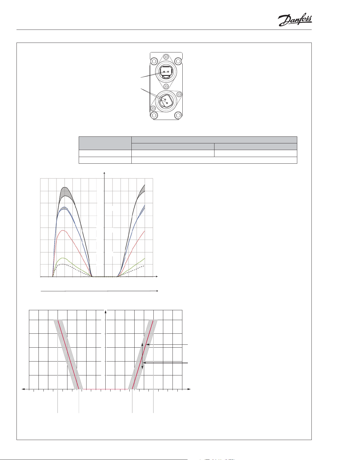
Ideal curve
Hysteresis
1
1600
800
1400
700
1200
600
1000
500
800
400
600
300
400
200
200
100
0
200
400
100
200
600
300
800
400
1000
500
1200
600
1400
700
280/560 mA 500/1000 mA280/560 mA500/1000 mA
1600
800
Current in mA
@ 12V
@ 24V
P301 775.A
The ideal curve is determined by the main spool neutral spring.
The hysteresis is aected by viscosity, friction, ow forces, dither frequency and modulation frequency.
2 L1407359 • Rev AB • Nov 2014 © Danfoss, 2014-11
Page 3

V310 475.A
Montage af PVHC
Installation of PVHC
Montage von PVHC
Installation de PVHC
8 ±0.5 Nm
[70 ±4.4 lbf •in]
5 [0.197]
Montage af magnetventilen som reservedel
Installation of the solenoid valve as spare part
Montage von dem Magnetventil als Ersatzteil
Installation de l'electrodistributeur de rechange
4 [0.16]
3 Nm
[26.5 lbf•in]
NB:
Pakningen i PVHC stikket samt pakningerne til
de enkelte ledninger, er afgørende for at korrekt
tæthed af stikket opnås.
NB:
The seal in the PVHC connector and the seals for
individual conductors are crucial for correctly sealing the connector.
NB:
Die Dichtung im PVHC-Stecker sowie die Dichtungen für die einzelnen Drähte sind für die Dichtheit
des Steckers von entscheidendem Einfluss.
NB:
Le joint de la prise PVHC ainsi les joints de chaque
conducteur, jouent un rôle essentiel dans la qualité
de l'étancheité de la prise.
Tilslutning
Connection
Anschluß
Raccordement
4 [0.16]
3 Nm
[26.5 lbf•in]
V310 017.A
Deutsch version
Pos. Description Qty Deutsch code numbers
1 Housing 1 DT06-2S
1 Lock Part 1 W2S
1 Pin Contact
2 0462-201-16141 when SOC 16-18 AWG*
2 0462-209-16141 when SOC 14-16 AWG*
1
V310 004.A
© Danfoss, 2014-11 L1407359 • Rev AB • Nov 2014 3
Page 4

[1.157]
Dimensioner for Deutsch version
Dimensions for Deutsch version
Abmessungen für Deutsch Versionen
Encombrements poor Deutsch Version
[0.236]
29.4
6
39 [1.535]
27 [1.063]
18.6
[0.732]
6
[0.236]
74
[2.913]
[1.339]
34
92
[3.622]
5.5
[0.217]
2.5
[0.098]
66.5
[2.618]
100.5
[3.957]
V310 474.A
4 L1407359 • Rev AB • Nov 2014 © Danfoss, 2014-11
Page 5

© Danfoss, 2014-11 L1407359 • Rev AB • Nov 2014 5
Page 6

WAdvarsel
Alle mærker og typer af retningsventiler – også proportional ventiler – kan svigte og forårsage alvorlig skade. Det er derfor vigtigt
at analysere maskinen i alle enkeltheder.
Da proportionalventiler anvendes under mange forskellige driftsbetingelser og i mange forskellige maskiner, er det alene maskinproducentens ansvar at træe det endelige produktvalg og sikre at samtlige maskinens krav til ydelse, sikkerhed og advarsler er
opfyldt.
Ved valg af reguleringssystem- og sikkerhedniveau- kan man f.eks. støtte sig til ISO 13849 (sikkerhedsrelaterede bestanddele i reguleringssystemet).
WWarning
All makes and all types of directional control valves – inclusive proportional valves – can fail and cause serious damage. It is therefore important to analyse all aspects of the application.
Because the proportional valves are used in many dierent operation conditions and applications, the manufacturer of the application is responsible for making the nal selection of the products- and assuring that all performance, safety and warning requirements of the application are met.
The process of choosing the control system – and safety level – could e.g. be governed by ISO 13849 (Safety related parts of control system).
WWarning
Alle Fabrikate und Typen von Wegeventilen – einschlieβlich proportionalventile – können versagen und schlimme Unfälle verursachen. Es ist daher wichtig, die Anwendung in allen Details zu analysieren.
Weil proportionalventile unter vielen unterschiedlichen Arbeitsbedingungen und in vielen verschiedenen Anwendungen benutzt
werden, trägt allein der Maschinenhersteller die verantwortung für seine endgültige wahl von produkt, und er ist ebenfalles dafür
verantwortlich, dass alle leistungs-, sicherheits- und warnungsanforderungen an seine maschine erfüllt sind.
Zur wahl vom Reglersystem und sicherheitsniveau kann man sich z.b. auf ISO 13849 stützen.
WAvertissement
Tous les distributeurs – y compris les distributeurs proportionnels – peuvent tomber en panne et entrainer de sérieux dommages.
C'est la raison pour laquelle il est important d'analyser chaque aspect de l'application. Les vannes proportionnelles étant utilisées
dans de nombreuses conditions d'exploitation et applications diérentes, le fabricant de l'application porte l'entiére responsabilité de la sélection nale des produits et du respect des exigences en matiére de rendement, de sécurité et d'avertissement. Le
choix du systéme de commande – et du niveau de sécurité – peut étre fait par exemple sur la base de la norme ISO 13849 (parties
du systéme de commande relatives á la sécurite).
6 L1407359 • Rev AB • Nov 2014 © Danfoss, 2014-11
 Loading...