

Page 1
Data Sheet
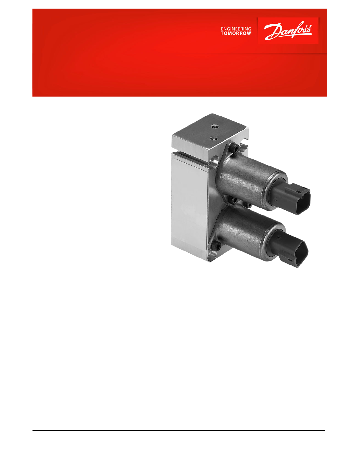
Electro-hydraulic actuator type
PVHC
The PVHC is an electrical actuator module for main
spool control in PVG 32 and PVG 100. The actuator
uses two current controlled proportional pressurereducing valves. PVHC does not use the known PVE
internal closed loop control technology, and
therefore does not offer any kind of fault monitoring
system, neither active nor passive.
Function
With electrical proportional actuation, the main spool
position is adjusted so that its position corresponds to
an electrical control signal.
The control signal is converted into a hydraulic
pressure signal that moves the main spool in the PVG.
This is done by means of two proportional pressurereducing valves. The electrical actuator can be
controlled either by a current amplifier card, or
directly from a programmable micro-controller.
(see drawing fig. 1 page 2).
Features
•
PVM current control signals
•
AMP JPT and DEUTSCH DT connector
options
•
12 V or 24 V supply options
•
Only to be used with 25 bar pilot
pressure and hydraulic spring
•
Only standard mounting on PVG 32 and
PVG 100.
Comprehensive technical literature is
online at powersolutions.danfoss.com
©
Danfoss | January 2018 11006692 | AI00000005en-US0303 | 1
Page 2
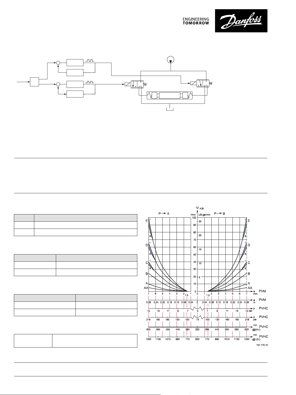
Fig 1.
157-764.10
+
-
Setpoint
Driver A
Current
Feedback A
Driver B
Current
Feedback B
+
---
W
Hydraulic Actuation
It is necessary only to use the PVHC in combination with 25 bar [362.6 psi] pilot pressure, 157B5190 (OC) and -5191 (CC), and standard FC
spools fitted for hydraulic actuation. See PVG 32 Technical Information DKMH.PK.570.C4.02. Because of the 25 bar pilot pressure, it is not
possible to combine PVHC with PVE on a PVG32 or PVG 100.
Warning
All marks and all types of directional control valves – including proportional valves – can fail and cause serious damage. It is therefore
important to analyze all aspects of the application. Because the proportional valves are used in many different operation conditions and
applications, the manufacturer of the application is alone responsible for making the final selection of the products – and assuring that
all performance, safety and warning requirements of the application are met. The process of choosing the control system – and safety
level – could e.g. be governed by EN 954-1 (Safety related parts of control system).
Technical data: Input-Output relation
Fig 2.
Temperature
Temperature range
Ambient -30°C to 80°C [-22 °F to 176°F]
Medium -20°C to 80°C [-4 °F to 176°F]
Input control
Parameter Control range: 12 V; 24 V
Current 0 - 1500 mA; 0 - 750 mA
Pressure control range 5 to 15 bar [72.5 to 217.5 psi]
Enclosure
Connector type Protection class
DEUTSCH DT IP 65
AMP JPT 12/24 V IP 65
Filtering
Filtering in the
hydraulic system
Danfoss can accept no responsibility for possible errors in catalogues, brochures and other printed material. Danfoss reserves the right to alter its products without notice. This also applies to products
already on order provided that such alterations can be made without changes being necessary in specifications already agreed.
All trademarks in this material are property of the respective companies. Danfoss and the Danfoss logotype are trademarks of Danfoss A/S. All rights reserved.
Max. permissible degree of contamination (ISO
4406, 1999 version): 23/19/16
2 | © Danfoss | January 2018 11006692 | AI00000005en-US0303
 Loading...