

Page 1
Technical Information
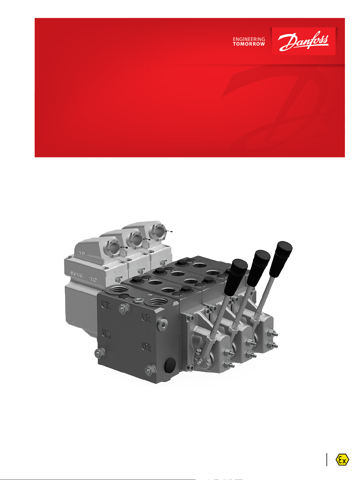
Proportional Valve Group
PVG-EX 32/128/256
www.danfoss.com
Page 2
Technical Information
PVG-EX 32/128/256 Proportional Valve Group
Revision history Table of revisions
Date Changed Rev
January 2022 Updated EU Declaration of Conformity 0301
November 2020 Added PVG 128/256, new EU Declaration of Conformity 0201
June 2019 New EU Declaration of Conformity 0103
May 2019 Updated EU Declaration of Conformity, and minor changes 0102
May 2019 First edition 0101
2 | © Danfoss | January 2022 BC290860493426en-000301
Page 3

Technical Information
PVG-EX 32/128/256 Proportional Valve Group
Contents
PVG-EX Introduction
Product certification........................................................................................................................................................................6
PVG-EX 32/128/256 Safety in Systems......................................................................................................................................6
Warnings..............................................................................................................................................................................................8
Nameplate description example.................................................................................................................................................9
Description of the EX code h version......................................................................................................................................10
EPL/Equipment category............................................................................................................................................................ 10
PVG-EX 32
General information......................................................................................................................................................................11
General description..................................................................................................................................................................11
Features........................................................................................................................................................................................11
Inlets..............................................................................................................................................................................................11
Work section housing............................................................................................................................................................. 11
Actuation methods.................................................................................................................................................................. 12
Sectional view............................................................................................................................................................................13
PVG-EX modules overview....................................................................................................................................................14
PVP Inlet Modules..........................................................................................................................................................................15
Open Center PVP...................................................................................................................................................................... 16
Open Center PVP with PPRV.................................................................................................................................................19
Open center PVP with HPCO and PVE PPRV................................................................................................................... 22
Closed Center PVP....................................................................................................................................................................25
Closed Center PVP with PPRV...............................................................................................................................................27
Closed center PVPV..................................................................................................................................................................29
Closed center PVPV with PPRV............................................................................................................................................ 30
Closed center PVPVM with PPRV.........................................................................................................................................32
Open/Closed center PVP with PPRV.................................................................................................................................. 34
Open/Closed center PVPM....................................................................................................................................................37
PVP Inlet Module Accessories....................................................................................................................................................38
PVPC without Check Valve.................................................................................................................................................... 39
PVPC with Check Valve...........................................................................................................................................................41
PVB Basic Modules.........................................................................................................................................................................42
Uncompensated PVB...............................................................................................................................................................44
Uncompensated PVB with load drop check valve........................................................................................................47
Uncompensated PVBZ with POC........................................................................................................................................ 50
Compensated PVB....................................................................................................................................................................51
Dampened Compensated PVB............................................................................................................................................ 54
Dampened compensated PVB with LS A/B.....................................................................................................................57
Compensated PVB with LS A/B............................................................................................................................................60
Compensated high flow PVB................................................................................................................................................64
Compensated high flow PVB with LS A/B........................................................................................................................67
Compensated PVBZ with POC............................................................................................................................................. 71
Compensated high flow PVBZ with POC......................................................................................................................... 73
Compensated high flow PVBZ with POC and manifold interface ..........................................................................75
PVB Basic Modules Accessories.................................................................................................................................................76
PVLP Shock and Anti-Cavitation Valve..............................................................................................................................76
PVLA Suction Valve.................................................................................................................................................................. 79
PVBS Main Spools...........................................................................................................................................................................80
PVBS fluid flow characteristics—Theoretical performance.......................................................................................81
PVBS Main Spools Part Numbers..............................................................................................................................................85
Flow Control Spools—Closed Neutral Position.............................................................................................................85
Flow Control Spools—Closed Neutral Position with A-float.................................................................................... 90
Flow Control Spools—Closed Neutral Position with B-float.....................................................................................91
Flow Control Spools—Closed Neutral Position with A-float for PVMF.................................................................92
Flow Control Spools—Closed Neutral Position with B-float for PVMF................................................................. 92
Flow Control Spools—Closed Neutral Position for PVMR......................................................................................... 93
Flow Control Spools—Open/Closed Neutral Position................................................................................................94
Flow Control Spools—Open/Closed A and Closed B Position.................................................................................94
Flow Control Spools—Throttled Open Neutral Position............................................................................................96
Flow Control Spools—Throttled Open Neutral Position for PVMR......................................................................100
©
Danfoss | January 2022 BC290860493426en-000301 | 3
Page 4

Technical Information
PVG-EX 32/128/256 Proportional Valve Group
Contents
Flow Control Spools—Throttled A to T Neutral Position.........................................................................................101
Flow Control Spools—Throttled B to T Neutral Position.........................................................................................102
Linear Flow Control Spools—Closed Neutral Position.............................................................................................103
Linear Flow Control Spools—Throttled Open Neutral Position............................................................................104
Linear Flow Control Spools—Open/Closed Neutral Position................................................................................105
Single Acting Cylinder Flow Control Spools—Neutral A-port Position..............................................................105
Single Acting Cylinder Flow Control Spools—Neutral B-port Position..............................................................106
Single Acting Cylinder Linear Flow Control Spools—Neutral B-port Position................................................ 106
Flow/Pressure Control Spools—Closed Neutral Position........................................................................................107
Flow/Pressure Control Spools—Throttled Open Neutral Position...................................................................... 108
Flow/Pressure Control Spools—Throttled Open B to T in Neutral Position..................................................... 109
Flow/Pressure Control Spools—Throttled Open A to T in Neutral Position.....................................................110
Flow/Pressure Control Spools—Throttled Open B to T in Neutral Position..................................................... 111
Flow/Pressure Control Spools—Open/Closed in Neutral Position......................................................................111
Flow/Pressure Control Spools—Closed A and Open/Closed B Position............................................................111
Pressure Control Spools—Closed Neutral Position...................................................................................................112
Pressure Control Spools—Throttled Open Neutral Position..................................................................................113
Pressure Control Spools—Throttled A to T in Neutral Position............................................................................ 114
Pressure/Flow Control Spools—Closed Neutral Position........................................................................................115
Pressure/Flow Control Spools—Closed Neutral Position with B-float............................................................... 116
Pressure/Flow Control Spools—Throttled Open Neutral Position...................................................................... 116
Pressure/Flow Control Spools—Open/Closed Neutral Position...........................................................................117
Pressure/Flow Control Spools—Open/Closed A and Closed B Position............................................................117
PVBS for PVBZ Main Spools Part Numbers......................................................................................................................... 117
PVBZ Flow Control Spools—Closed Neutral Position...............................................................................................117
PVBZ Flow Control Spools—Closed Neutral Position with A-float...................................................................... 119
PVBZ Flow Control Spools—Closed Neutral Position with B-float.......................................................................120
PVBZ Flow Control Spools—Throttled Open Neutral Position with B-float..................................................... 120
PVBZ Linear Flow Control Spools—Closed Neutral Position................................................................................. 121
PVBZ Single Acting Cylinder Flow Control Spools—Closed Neutral A-port Position................................... 121
PVBZ Single Acting Cylinder Flow Control Spools—Closed Neutral B-port Position....................................122
PVBZ Single Acting Cylinder Linear Flow Control Spools—Closed Neutral B-port Position...................... 122
PVBZ–HS Single Acting Cylinder Flow Control Spools—Closed Neutral Position......................................... 122
PVG-EX 32 Actuation..................................................................................................................................................................122
PVM Manual actuation.........................................................................................................................................................124
PVMD detention covers.......................................................................................................................................................126
PVMD Detention Covers detailed information............................................................................................................126
PVH Hydraulic Actuation.....................................................................................................................................................127
PVSI End Plates............................................................................................................................................................................. 127
PVSI..............................................................................................................................................................................................127
PVSI with LX-connection..................................................................................................................................................... 129
PVSKM Full Flow Cut Off Modules.........................................................................................................................................130
PVSKM Functionality.............................................................................................................................................................131
PVSKM Spool............................................................................................................................................................................133
PVAS Stay Bolts.............................................................................................................................................................................134
PVAS Part Numbers............................................................................................................................................................... 135
PVG-EX 32 modules total length...................................................................................................................................... 135
PVG-EX 128/256
General Information................................................................................................................................................................... 136
PVG-EX 128/256 Proportional Valve Group..................................................................................................................136
PVG-EX 128/256 general description..............................................................................................................................137
Features of the PVG-EX 128/256 valve........................................................................................................................... 137
PVG-EX 128/256 PVPV Inlet Modules................................................................................................................................... 138
PVG-EX 128/256 Closed Center PPRV for PVE Activation and/or Mechanical..................................................139
PVG-EX 128/256 PPRV for PVH Activation and/or Mechanical ............................................................................. 140
PVG-EX PVB 128 Variant Overview........................................................................................................................................141
PVG-EX PVB 128 3-way Compensator.............................................................................................................................142
PVG-EX PVB 128 3-way Compensator with LS A/B.....................................................................................................145
PVG-EX PVB 128 3-way Compensator with LS A/B and PVLP.................................................................................149
4 | © Danfoss | January 2022 BC290860493426en-000301
Page 5

Technical Information
PVG-EX 32/128/256 Proportional Valve Group
Contents
PVG-EX PVB 256 Variant Overview........................................................................................................................................154
PVG-EX PVB 256 3-way Compensator.............................................................................................................................155
PVG-EX PVB 256 3-way Compensator with LS A/B.....................................................................................................159
PVG-EX PVB 256 3-way Compensator with LSA/B and PVLP..................................................................................163
PVG-EX PVB 256 3-way Compensator with LS A/B, PVLP and Turbo...................................................................168
PVG-EX PVLP Shock and PVLA Suction Valves..................................................................................................................173
PVG-EX PVLP Overview........................................................................................................................................................ 173
PVG-EX PVLP Technical Data..............................................................................................................................................173
PVG-EX 128/256 PVBS Main Spool........................................................................................................................................ 176
PVG-EX PVBS Main Spools variant overview................................................................................................................ 176
PVG-EX Flow control spools..........................................................................................................................................176
PVG-EX PVBS main spools product details....................................................................................................................176
PVG-EX PVS Main spools part numbers......................................................................................................................... 179
PVG-EX Flow control spools..........................................................................................................................................179
PVG-EX PVM Manual Activation.............................................................................................................................................181
PVG-EX PVM Technical Data...............................................................................................................................................182
PVG-EX PVH Hydraulic Actuation.......................................................................................................................................... 183
PVG-EX PVH Technical Data............................................................................................................................................... 184
PVG-EX PVMD Cover Manual Actuation Only................................................................................................................... 185
PVG-EX PVMD Part Numbers............................................................................................................................................. 185
PVG-EX PVSI/PVGI End and Interface Plates.......................................................................................................................186
PVG-EX PVSI with or without LX-connection............................................................................................................... 187
PVG-EX PVSI with P and T port connections.................................................................................................................188
PVG-EX PVGI Interface Plate...............................................................................................................................................189
PVG-EX PVAS................................................................................................................................................................................. 190
PVG-EX PVAS for Combo..................................................................................................................................................... 190
PVG-EX PVAS Part Number Overview.............................................................................................................................191
PVG-EX 128/256 Valve Schematics........................................................................................................................................193
PVG-EX Valve Schematics....................................................................................................................................................193
Dimensions Overview................................................................................................................................................................195
Dimension Overview for PVG-EX 128/256.................................................................................................................... 195
PVG-EX Specifications example........................................................................................................................................ 197
EU declaration of conformity
EU declaration of conformity page 1....................................................................................................................................198
EU declaration of conformity page 2....................................................................................................................................199
EU declaration of conformity page 3....................................................................................................................................200
EU declaration of conformity page 4....................................................................................................................................201
EU declaration of conformity page 5....................................................................................................................................202
©
Danfoss | January 2022 BC290860493426en-000301 | 5
Page 6

W
Technical Information
PVG-EX 32/128/256 Proportional Valve Group
PVG-EX Introduction
The Danfoss PVG-EX program is an explosion-proof PVG designed to be used in Ex hazardous areas like
mining and oil and gas industries.
Product certification
The PVG-EX is developed according to and in compliance with:
EU Directive 2014/34/EU Equipment for explosive atmosphere - ATEX
•
EN 60079-0:2018 Electrical apparatus for explosive gas atmospheres-part 0
•
EN 80079-36:2016 Non-electrical equipment for explosive atmospheres – Basic method and
requirements
•
EN 80079-37:2016 Non-electrical equipment for explosive atmospheres – Non-electrical type of
protection constructional safety “c”, control of ignition sources “b”, liquid immersion “k”
•
EN 80079-38:2016 Equipment and components in explosive atmospheres in underground mines
PVG-EX 32/128/256 Safety in Systems
All types and brands of control valves, including proportional valves, can fail. Therefore, the necessary
protection against the serious consequences of a functional failure should always be built into the
system.
General safety considerations
For each application an assessment should be made for the consequences of the system in case of
pressure failure and uncontrolled or blocked movements.
Warning
Because the proportional valve is used in many different applications and under different operating
conditions, it is the sole responsibility of the manufacturer to ensure that all performance, safety and
warning requirements of the application is met in his selection of products and complies with relevant
machine specific and generic standards.
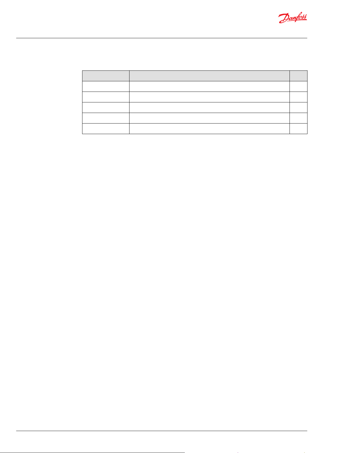
Control system example
An example of a control system using an aerial lift is shown below:
6 | © Danfoss | January 2022 BC290860493426en-000301
Page 7
W
Technical Information
PVG-EX 32/128/256 Proportional Valve Group
PVG-EX Introduction
Aerial lift
This example breaks down the control system into smaller bits explaining the architecture in depth. Even
though many Danfoss components are used in the PVG control system.
The function of the control system is to use the output from the PVE together other external sensors to
ensure the PLUS+1 main controllers correct function of the aerial lift.
Electrical block diagram
Warning
It is the responsibility of the equipment manufacturer that the control system incorporated in the
machine is declared as being in conformity with the relevant machine directives.
©
Danfoss | January 2022 BC290860493426en-000301 | 7
Page 8

C
W
W
W
W
Technical Information
PVG-EX 32/128/256 Proportional Valve Group
PVG-EX Introduction
Caution
A mix of electrical actuation and hydraulic actuation on the same valve stack is not safe. PVE and PVH are
designed for different pilot pressure.
Cost-free repairs, as mentioned in Danfoss General Conditions of Sale, are carried out only at Danfoss or
at service shops authorized by Danfoss.
Warnings
Warning
All brands and all types of directional control or proportional valves, which are used in many different
operation conditions and applications, can fail and cause serious damage.
Analyze all aspects of the application. The machine builder/system integrator alone is responsible for
making the final selection of the products and assuring that all performance, safety and warning
requirements of the application are met.
The process of choosing the control system and safety levels is governed by Machinery Directive
2006-42-EC, and harmonized standard EN 13849 (Safety related requirements for control systems).
Warning
All national safety regulations must be fulfilled in connection with installation, start-up and operation of
Danfoss PVG-EX.
Furthermore, the requirements of the Declaration of Conformity and national regulations for installations
in potentially explosive atmospheres applies as well. Disregarding such regulations involves a risk of
serious personal injury or extensive material damage.
Warning
Work in connection with the valve group must be performed only by professionals and qualified persons.
Warning
PVG with non-conductive coating must have preventive protection against electrostatic charge by an
earthed metal connection.
8 | © Danfoss | January 2022 BC290860493426en-000301
Page 9
PVG-Ex
Ex h db I Mb T5...T4
Ta -30° to +60°C
111328133613A147305-EX
Ԑx
I M2
MADE IN DENMARK
Nordborgvej 81
6430 Nordborg, DK
PVG
XXXXXXXXXXXXXXXXXXX
RATED P:
MADE IN DENMARK
Nordborgvej 81, 6430 Nordborg, DK
SEE INSTRUCTION
PVG
XXXXXXXX
6
1
4
5
3
2
Technical Information
PVG-EX 32/128/256 Proportional Valve Group
PVG-EX Introduction
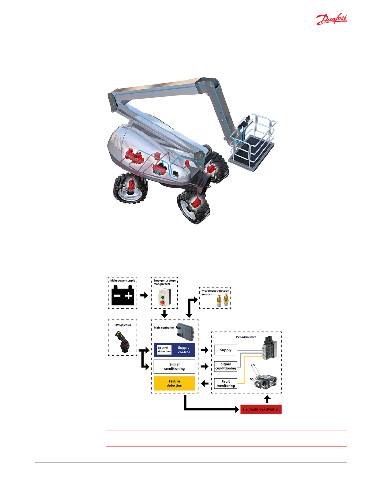
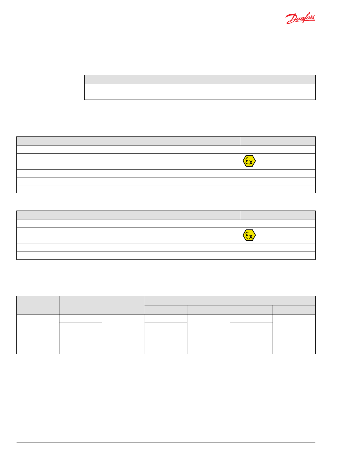
Nameplate description example
Nameplate key
Nameplate legend
Number Description
1 PVG Valve Group code number
2
3 CE Conformity marking
4 EU marking (per 80079) - Standard part
5 Ambient temperature range
6 EU marking (per 2014/34/EU) - Directive part
©
Danfoss | January 2022 BC290860493426en-000301 | 9
Code number, production date,
and serial number
Example: 42 12 C xxxxxx
Week: 42, Year: 2012,
Day: C=Wednesday (A=Monday), Serial number
Page 10
Technical Information
PVG-EX 32/128/256 Proportional Valve Group
PVG-EX Introduction
T-category with ambient temperature at 65°C [149°F]
Oil inlet temperature T-category
≤ 79°C [174°F] T5
79 - 90°C [174 - 194°F] T4
Description of the EX code h version
Ex marking (EN 80079-36 standard part)
Description EU Marking
Protection principle h
Explosion protection marking
Equipment group I / II
Equipment protection level (EPL) Mb / Gb
T-class T5...T4
Ex marking (EU Directive part)
Description EU Marking
CE conformity marking CE
Explosion protection marking
Equipment Group I / II
Equipment Category M2 / 2G
EPL/Equipment category
EPL/Equipment category
Definition Level of protection Typical zone of
application
Mines Very high N/A Ma I M1 I
High Mb M2
Gas atmosphere Very high 0 Ga II 1G II
High 1 Gb 2G
Enhanced 2 Gc 3G
IEC EU
EPL Group Category Group
10 | © Danfoss | January 2022 BC290860493426en-000301
Page 11

Technical Information
PVG-EX 32/128/256 Proportional Valve Group
PVG-EX 32
General information
General description
PVG 32 is a hydraulic load sensing (LS) valve designed to give maximum flexibility. From a simple load
sensing directional valve, to an advanced electrically controlled load-independent proportional valve.
The PVG 32 modular system makes it possible to build up a valve group to meet the different functional
requirements precisely.
The compact external dimensions of the valve remain unchanged whatever combination is specified.
The PVG 32 interfaces to other valve families like PVG 128/256 enabling all machine functions being
controlled from one single valve stack.
Features
Features of the PVG 32 include:
•
Load-independent flow control:
Oil flow to an individual function is independent of the load pressure of this function
‒
Oil flow to one function is independent of the load pressure of other functions
‒
•
Good regulation characteristics
•
Energy-saving
•
Up to 12 basic modules per valve group
•
Several types of connection threads
•
Low weight
•
Compact design and installation
Inlets
The inlets include:
•
Built-in pressure relief valve
•
Pressure gauge connection
•
Versions for different pump types
Open Center systems with fixed displacement pumps
‒
Closed Center systems with variable displacement pumps
‒
•
Integrated pilot oil supply
Work section housing
Our work section housing includes:
•
Interchangeable spools
•
Pressure gauge connection
•
Versions for different application needs
Built-in compensator for load independent flow
‒
Built-in load holding check valve in P-channel
‒
Integrated shock/suction valve
‒
Integrated local pressure relief valve
‒
©
Danfoss | January 2022 BC290860493426en-000301 | 11
Page 12

Technical Information
PVG-EX 32/128/256 Proportional Valve Group
PVG-EX 32
Actuation methods
Our actuation methods include:
•
Manual control with lever
•
Manual with friction detent
•
Hydraulic
•
Electro-hydraulic
ON/OFF control
‒
Ratiometric proportional
‒
CANbus proportional
‒
PWM proportional
‒
12 | © Danfoss | January 2022 BC290860493426en-000301
Page 13
Technical Information
PVG-EX 32/128/256 Proportional Valve Group
PVG-EX 32
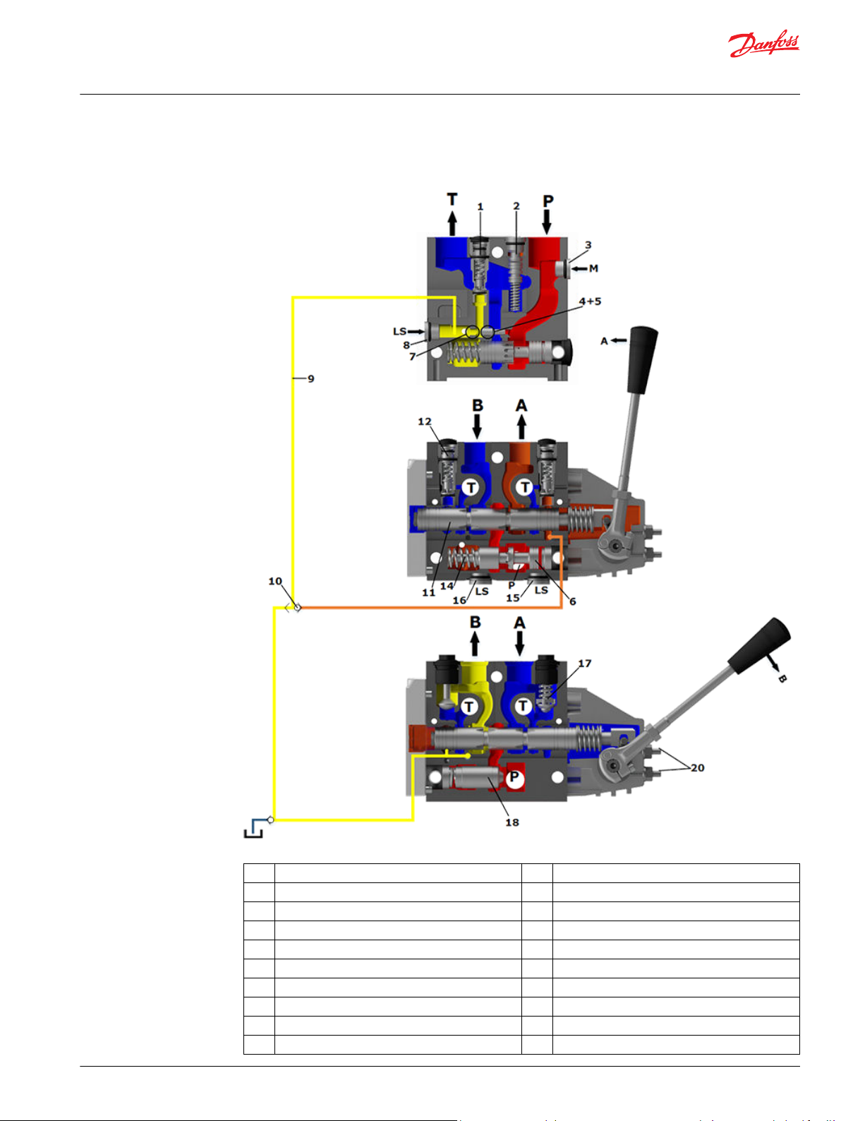
Sectional view
1. Pressure relief valve 11. Main spool
2. Pressure reduction valve for pilot oil supply 12. LS pressure limiting valve
3. Pressure gauge connection 13. Shock and suction valve, PVLP
4. Plug, open center 14. Pressure compensator
5. Orifice, closed center 15. LS connection, port A
6. Pressure adjustment spool 16. LS connection, port B
7. Plug, closed center 17. Suction valve, PVLA
8. LS connection 18. Load drop check valve
9. LS signal 19. Pilot oil supply for PVE
10. Shuttle valve 20. Maximum oil flow adjustment screws for A/B ports
©
Danfoss | January 2022 BC290860493426en-000301 | 13
Page 14
Technical Information
PVG-EX 32/128/256 Proportional Valve Group
PVG-EX 32
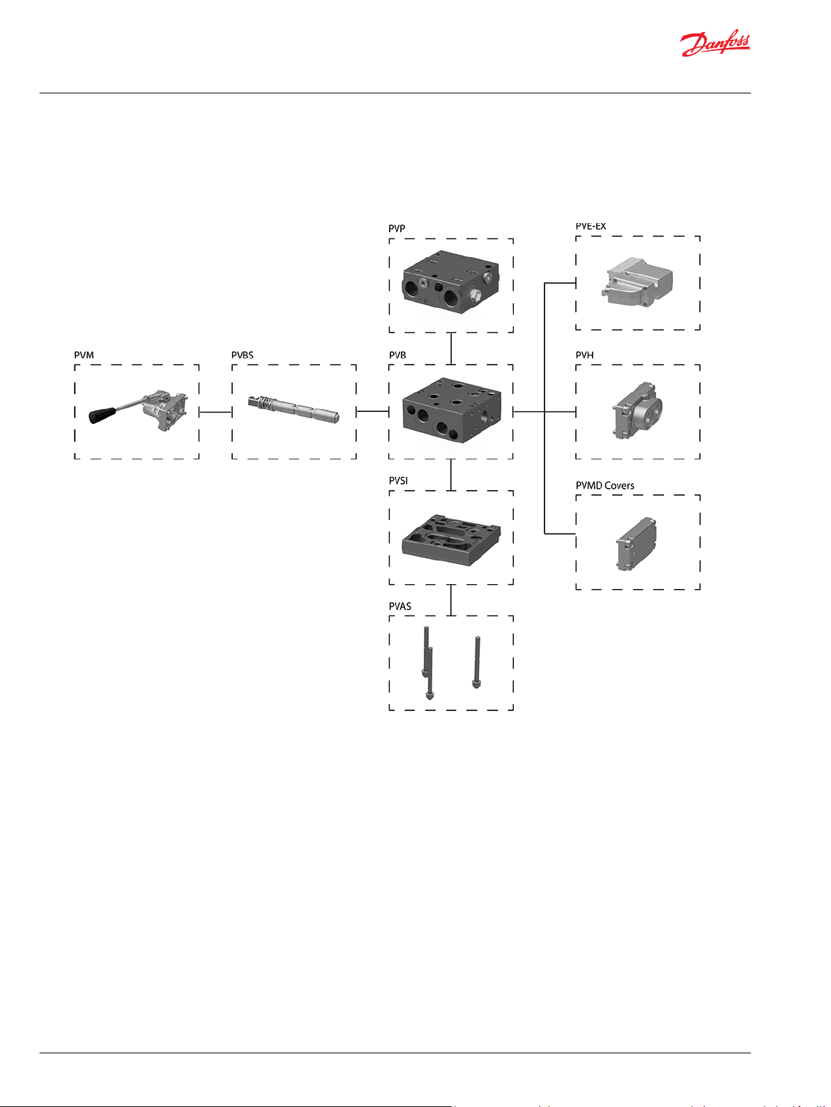
PVG-EX modules overview
PVG-EX 32 modules exploded view
PVG modules navigation
•
PVP Inlet Modules on page 15
•
PVB Basic Modules on page 42
•
PVBS Main Spools on page 80
•
PVSKM Full Flow Cut Off Modules on page 130
•
PVAS Stay Bolts on page 134
14 | © Danfoss | January 2022 BC290860493426en-000301
Page 15
112.5 [4.43]
110 [4.33]
95 [3.74]
23 [0.9]
48 [1.89]
Technical Information
PVG-EX 32/128/256 Proportional Valve Group
PVG-EX 32
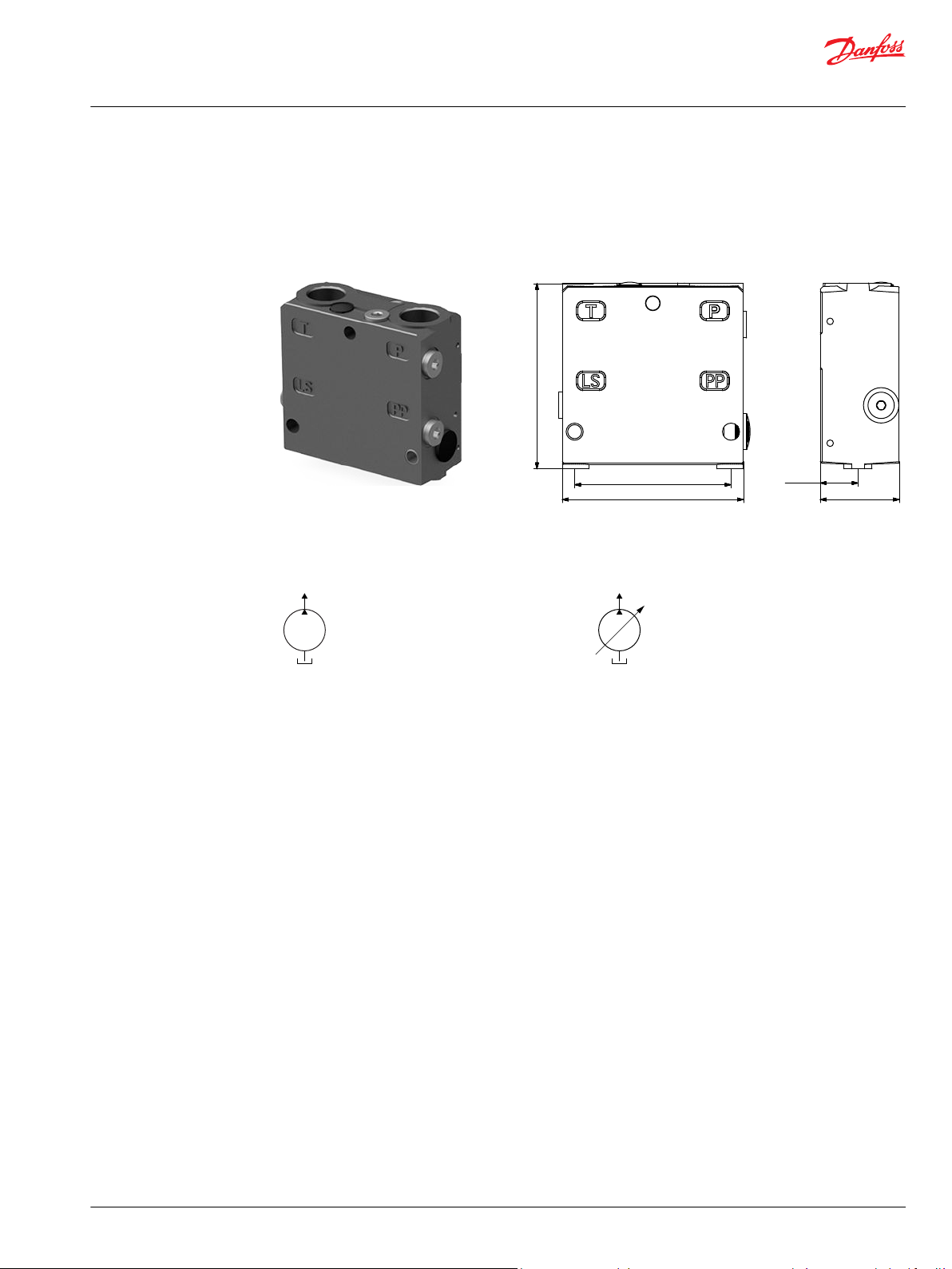
PVP Inlet Modules
The PVG-EX 32 PVP inlet modules, also referred to as pump side modules, act as an interface between the
PVG-EX 32 proportional valve group and the hydraulic pump and tank reservoir.
PVP Inlet Module PVP inlet module dimensions
Weight: 3.1 kg [6.9 lb]
Fixed displacement pump symbol Variable displacement pump symbol
The PVP inlet module variants are based on a generic platform with a selection of additional features,
enabling you to tailor the PVP to suit the demands of any hydraulic system:
Open Center PVP on page 16 (for fixed displacement pumps)
•
Open Center PVP with PPRV on page 19 (for fixed displacement pumps)
•
Open center PVP with HPCO and PVE PPRV on page 22 (for fixed displacement pumps)
•
Closed Center PVP on page 25 (for variable displacement pumps)
•
Closed Center PVP with PPRV on page 27 (for variable displacement pumps)
•
Closed center PVPV with PPRV on page 30 (for variable displacement pumps)
•
Closed center PVPVM with PPRV on page 32 (for variable displacement pumps)
•
Open/Closed center PVP with PPRV on page 34
•
Open/Closed center PVPM on page 37
•
©
Danfoss | January 2022 BC290860493426en-000301 | 15
Page 16
LS
T
P
M
Technical Information
PVG-EX 32/128/256 Proportional Valve Group
PVG-EX 32
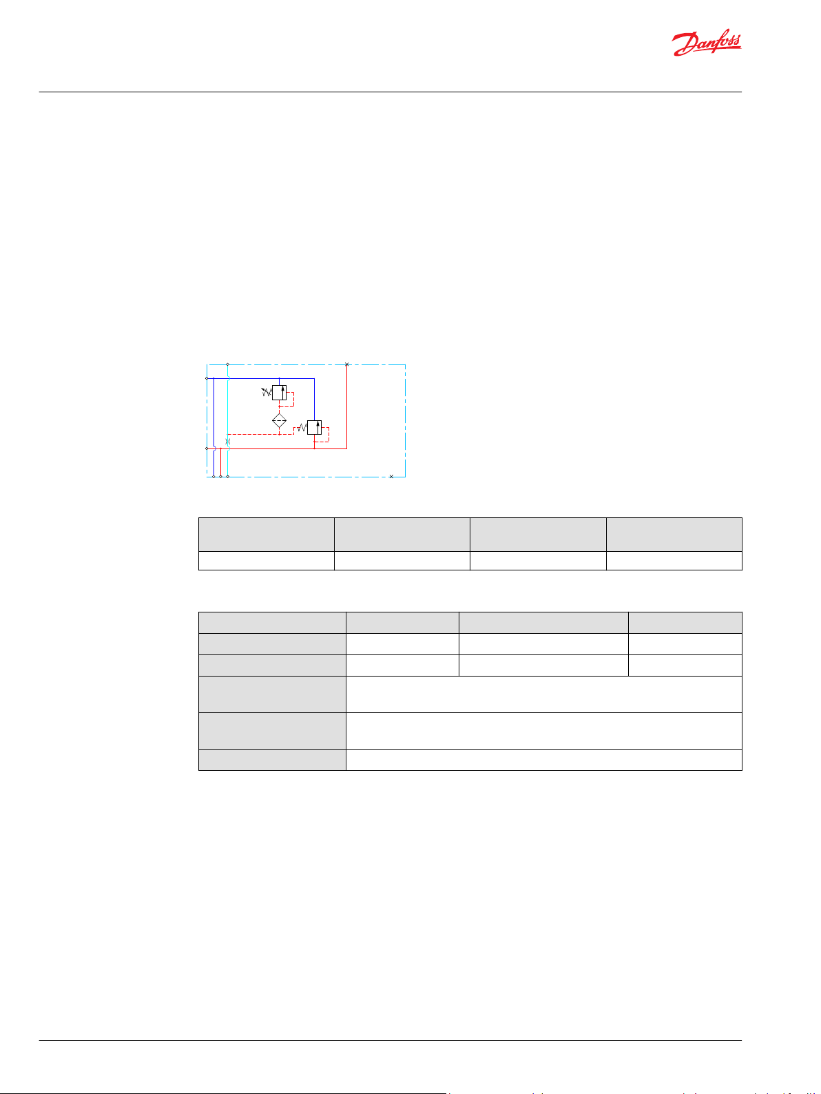
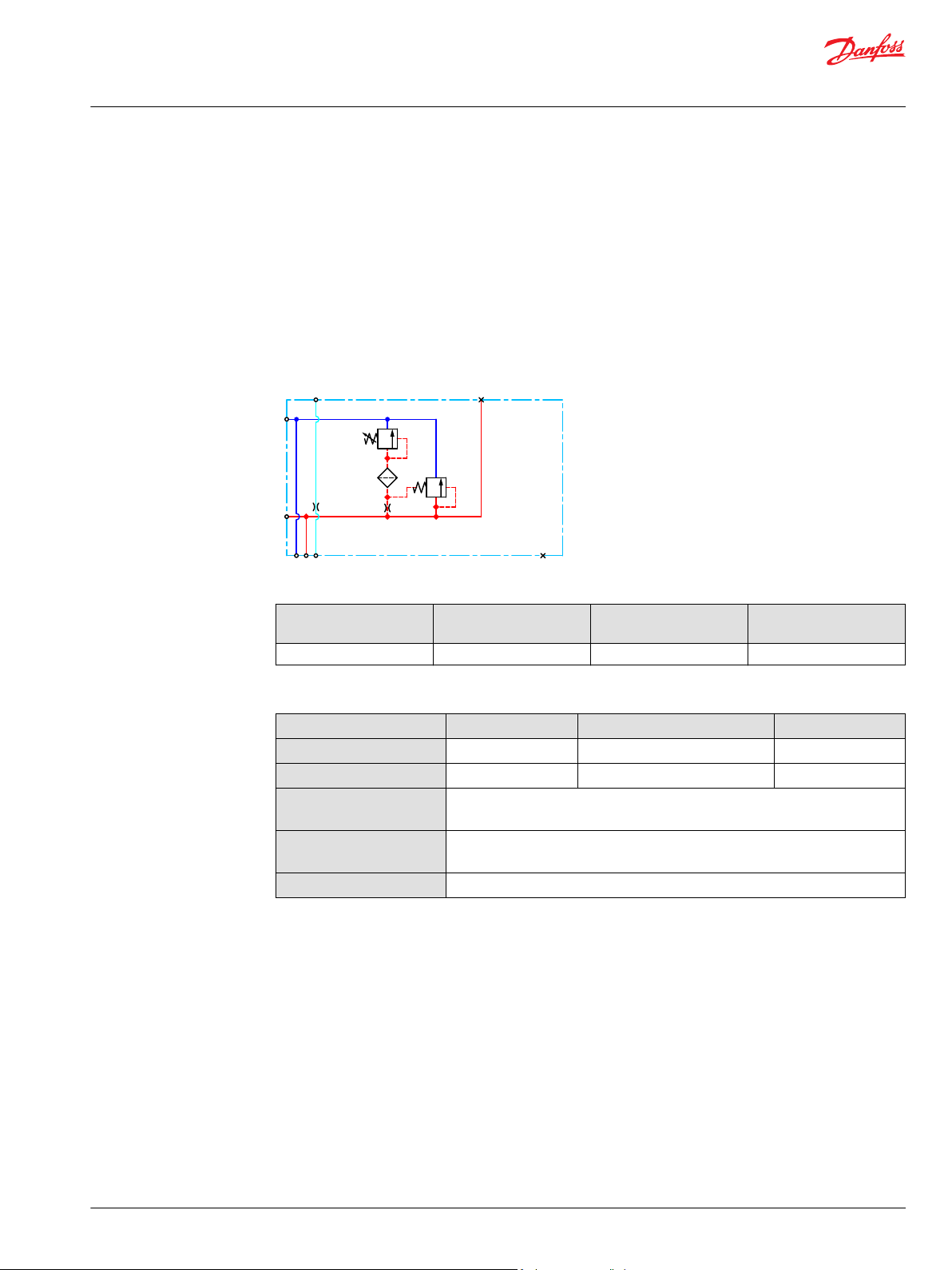
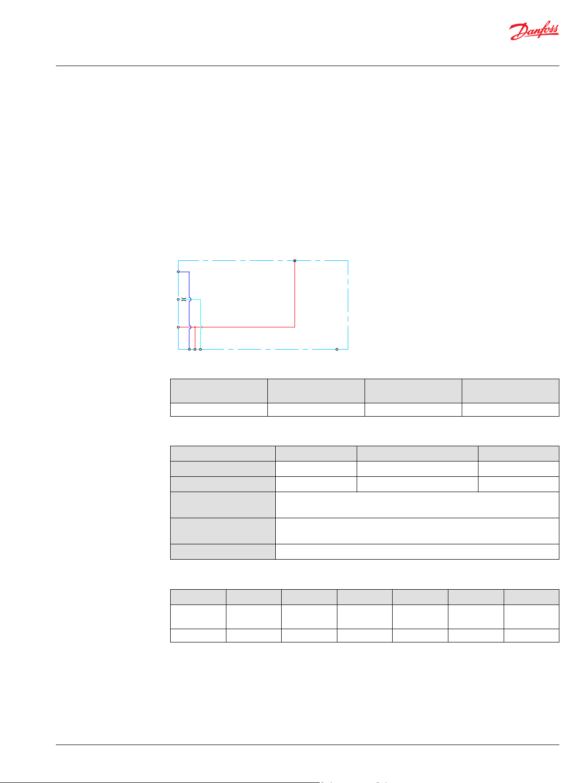
Open Center PVP
The basic Open Center PVP inlet module is intended for use with fixed displacement pumps in
applications, where a valve group with mechanically controlled work sections is desired, or where the
pilot pressure to the valve group is supplied externally.
The Open Center PVP features:
Integrated LS pressure relief valve
•
Threaded ports for P/T/LS and M measuring gauge
•
Optional T0 facility and external T0 port
•
All modules can be manually activated with the PVM actuation.
Open center PVP schematic
Technical specification for PVP
Max. P-port continuous Max. P-port intermittent Max. T-port static/
dynamic
350 [5076 psi] 400 bar [5800 psi] 25/40 bar [365/580 psi] 140 l/min [37 US gal/min]
Max. rated flow
Technical specification
Parameter Minimum Recommended range Maximum
Fluid temperature
Fluid viscosity
Fluid cleanliness
(mechanical activation)
Fluid cleanliness
(PVE activation)
Operating temperature
-30°C [-22°F] 30 to 60°C [86 to 140°F] 90° [194°F]
4 mm2/s [39 SUS] 12 to 75 mm2/s [65 to 347 SUS] 460 mm2/s [2128 SUS]
23/19/16 (according to ISO 4406)
18/16/13 (according to ISO 4406)
Ambient: -30 to 60°C [-22 to 140°F]
16 | © Danfoss | January 2022 BC290860493426en-000301
Page 17
[l/min]
[US gal/min]
200
150
100
50
20
40
60
80
100
120
140
Q
300
250
P
P
2000
1000
0
0
0
204 8
28
24
32
36
12
16
0
3000
4000
[psi] Q(bar)
(l/min)
[US gal/min]
20
20
40
60 80
100
120
140
16
12
8
4
160
80
0
0
0
240
[psi] (bar)
4
8
12
16
20
24
28
32
36
0
Technical Information
PVG-EX 32/128/256 Proportional Valve Group
PVG-EX 32
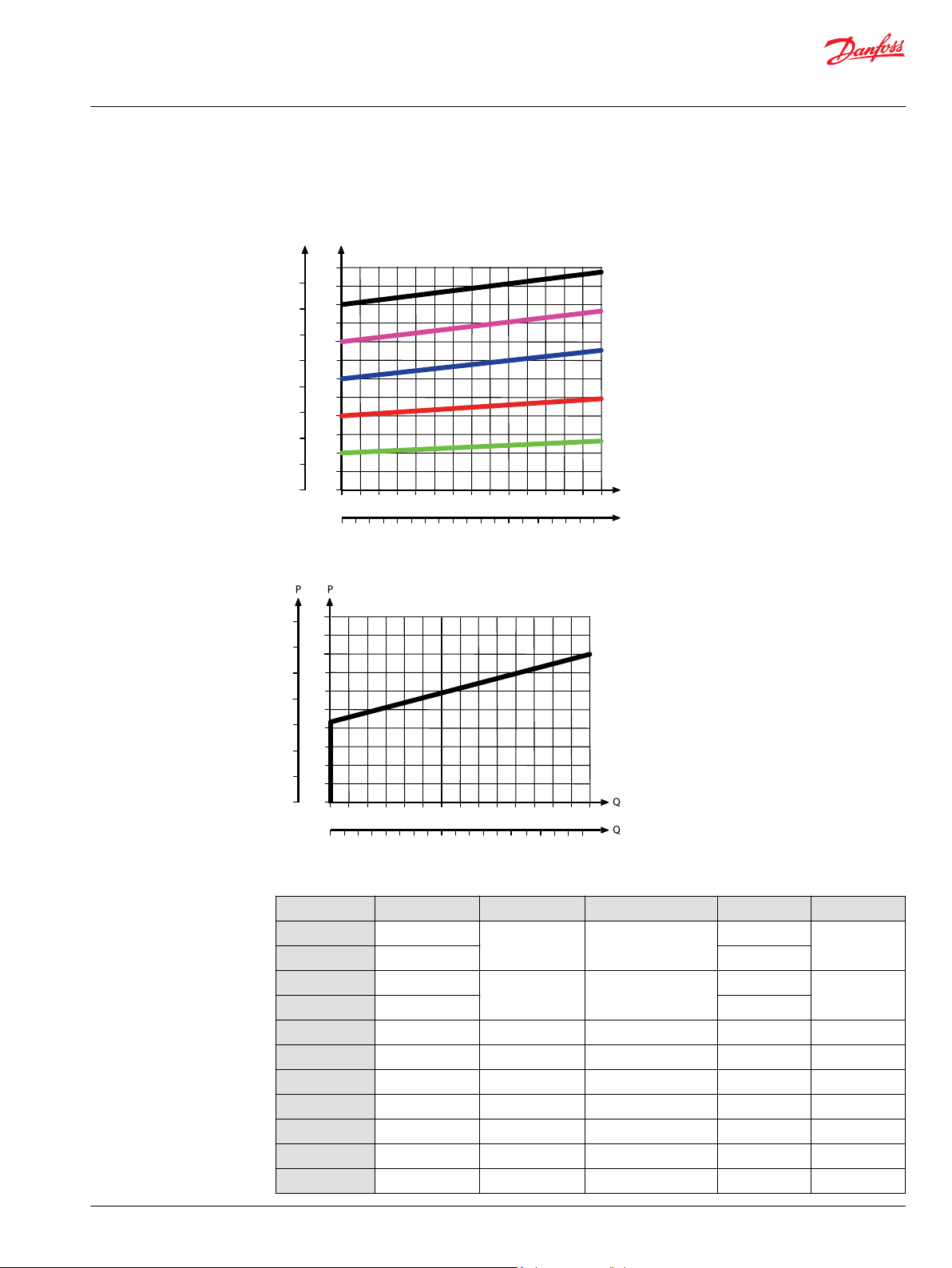
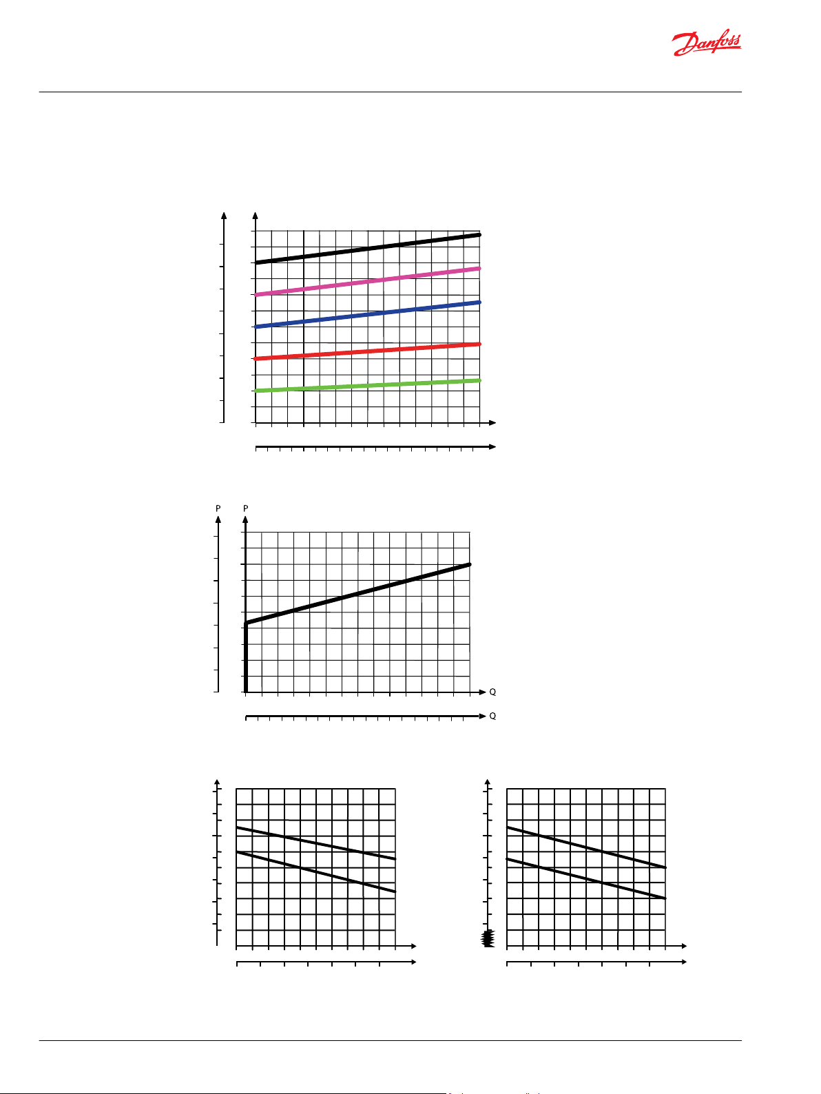
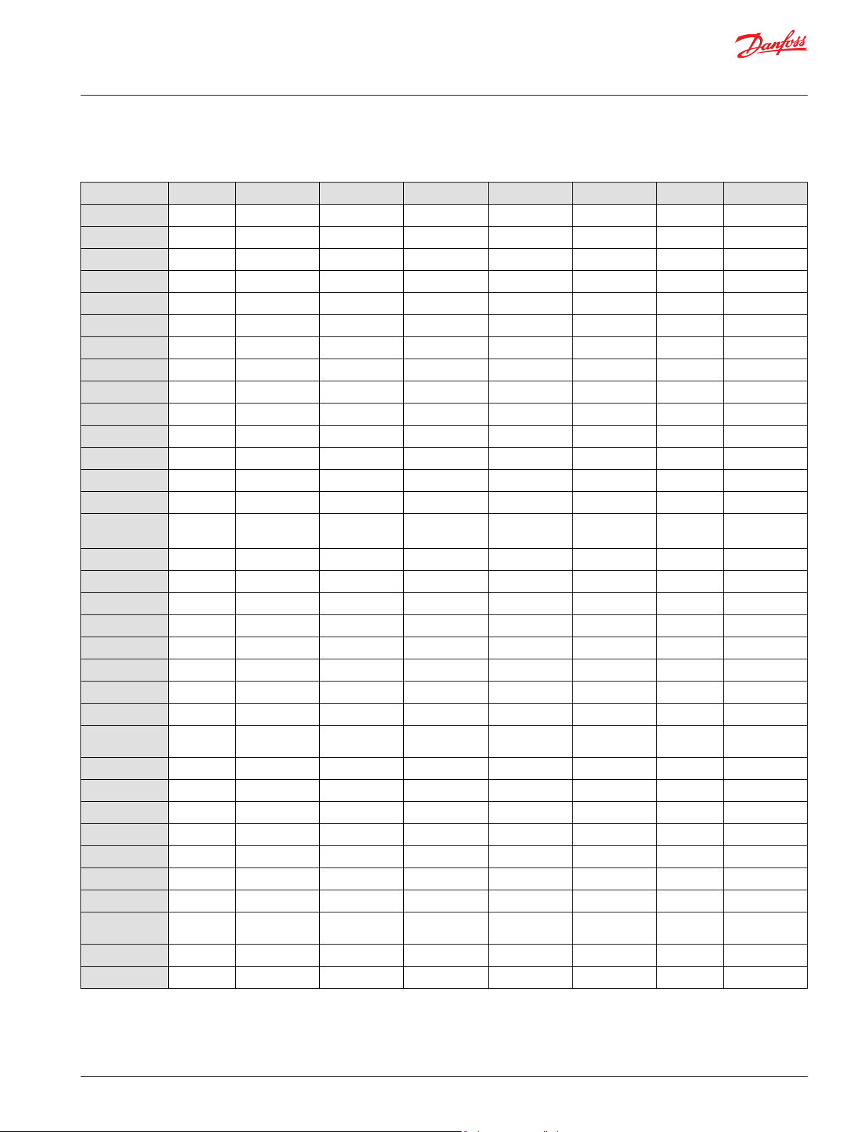
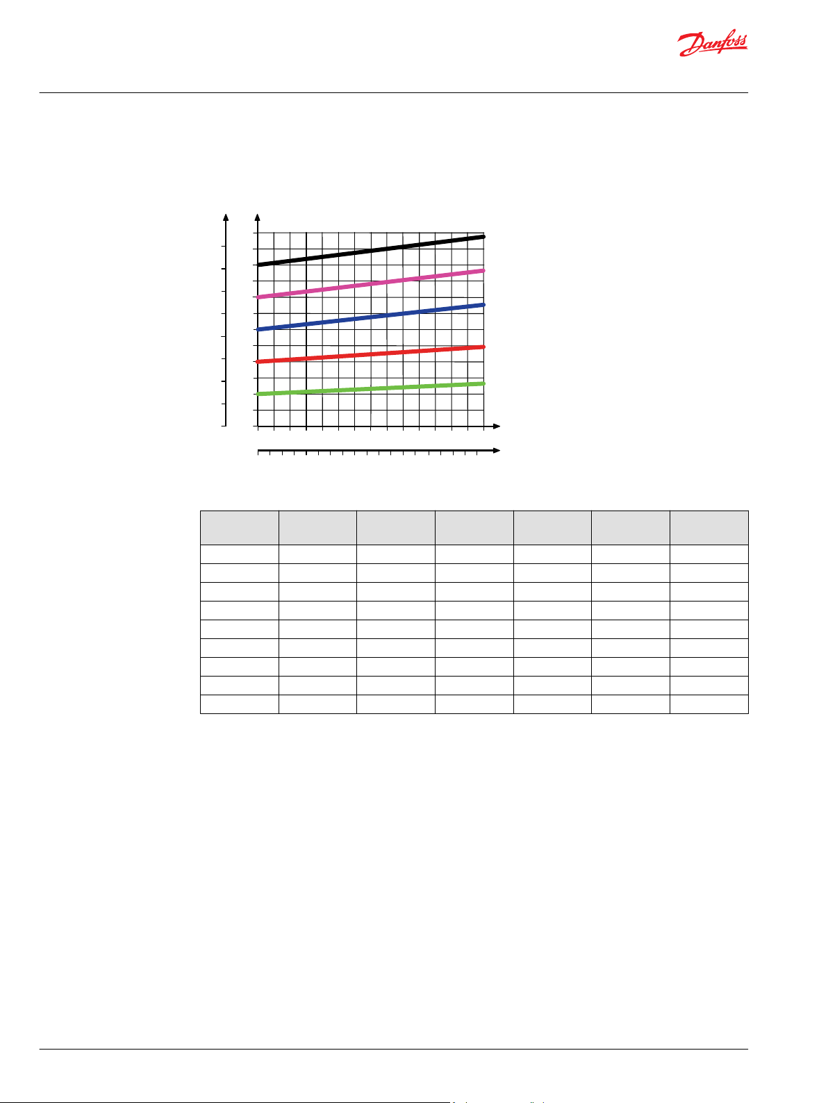
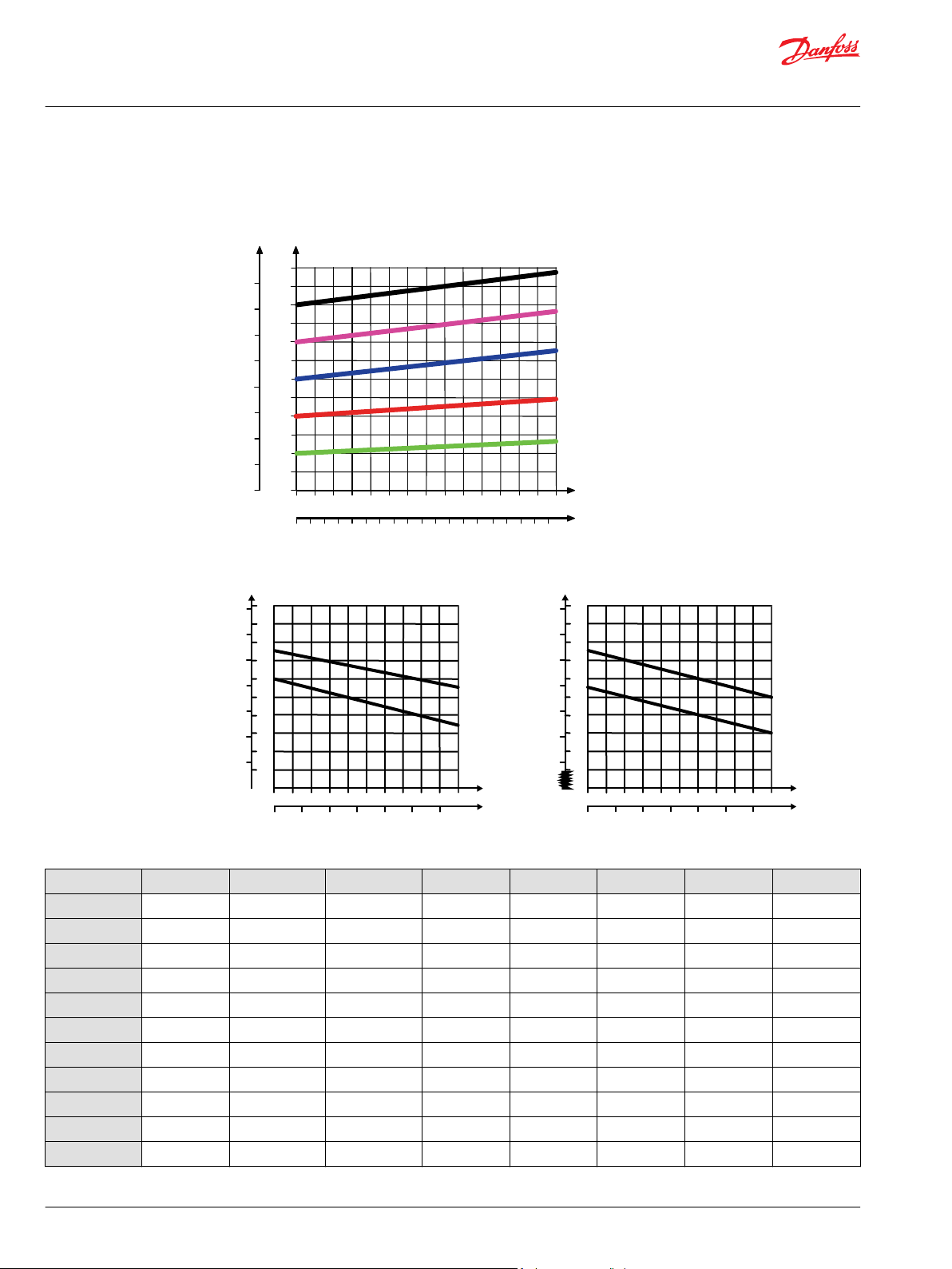
Theoretical Performance Graphs
Integrated LS pressure relief valve characteristics
Neutral by-pass pressure drop characteristics
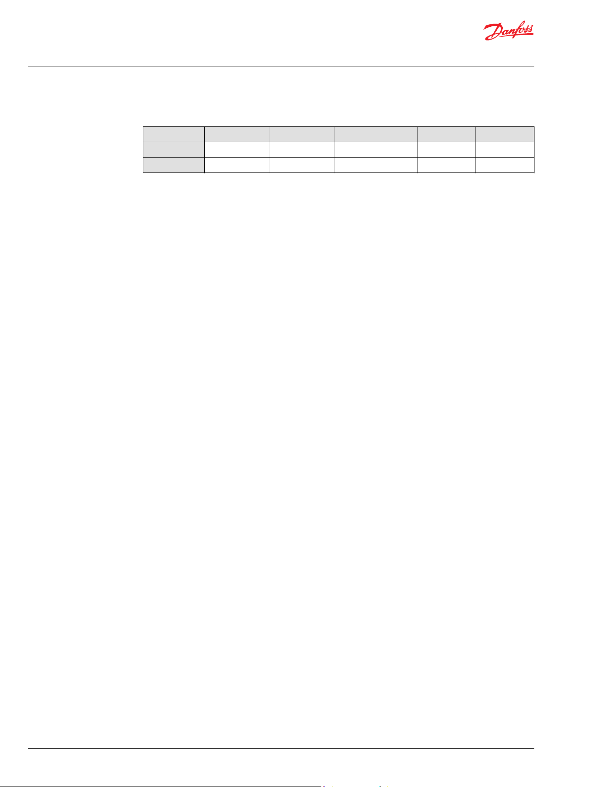
Part numbers for Open Center PVP
Part number P-port T-port LS-, M-port (LS1*) T0-port Mounting
157B5000
157B5100
157B5200
157B5300
11008852
11030545
11053974
11151852
157B5908
157B5921
157B5925
G1/2”
G3/4” –
G3/4” G1/4”
7/8-14 UNF
1-1/16 UN -
1
G1/2 G3/4 G1/4 (G1/8) - M8
1 1/16-12 UNF 1/2-20 UNF
G3/4 G3/4 G1/4 (G1/4) G1/4 M8
G3/4 G3/4 G1/4 (G1/4) G1/4 M8
1 1/16-12 UNF 1 1/16-12 UNF 9/16-18 UNF 9/16-18 UNF M8
1 1/16-12 UNF 1 1/16-12 UNF 1/2-20 UNF - M8
JIS 1/2 JIS 3/4 JIS 1/4 - M8
JIS 1/2 JIS 3/4 JIS 1/4 - M8
M8
5/16-18 UNC
©
Danfoss | January 2022 BC290860493426en-000301 | 17
Page 18
Technical Information
PVG-EX 32/128/256 Proportional Valve Group
PVG-EX 32
Part numbers for Open Center PVP (continued)
Part number P-port T-port LS-, M-port (LS1*) T0-port Mounting
157B5945
157B5990
*
LS1 is an extra LS-port.
1
Dampened LS response
2
No relief valve
G1/2 G3/4 G1/4 (G1/8) - M8
2
1 1/16-12 UNF 1 1/16-12 UNF - - M8
18 | © Danfoss | January 2022 BC290860493426en-000301
Page 19
LS
T
P
M
Pp
Technical Information
PVG-EX 32/128/256 Proportional Valve Group
PVG-EX 32
Open Center PVP with PPRV
The Open Center PVP inlet with integrated pilot pressure reduction valve (PPRV) is intended for use with
fixed displacement pumps in applications, where a valve group with electro-hydraulically or hydraulically
controlled work sections is desired (PVE or PVH/PVHC).
The Open Center PVP with PPRV features:
Integrated LS pressure relief valve
•
Threaded ports for P/T/LS and M measuring gauge
•
Integrated pilot pressure reducing valve (PPRV) for PVE or PVH/PVHC
•
Optional T0 facility and external T0 port
•
Optional external pilot pressure port (Pp)
•
All modules can be manually activated with the PVM actuation.
Open center PVP with PPRV schematic
Technical specification for PVP
Max. P-port continuous Max. P-port intermittent Max. T-port static/
dynamic
350 [5076 psi] 400 bar [5800 psi] 25/40 bar [365/580 psi] 140 l/min [37 US gal/min]
Max. rated flow
Technical specification
Parameter Minimum Recommended range Maximum
Fluid temperature
Fluid viscosity
Fluid cleanliness
(mechanical activation)
Fluid cleanliness
(PVE activation)
Operating temperature
-30°C [-22°F] 30 to 60°C [86 to 140°F] 90° [194°F]
4 mm2/s [39 SUS] 12 to 75 mm2/s [65 to 347 SUS] 460 mm2/s [2128 SUS]
23/19/16 (according to ISO 4406)
18/16/13 (according to ISO 4406)
Ambient: -30 to 60°C [-22 to 140°F]
©
Danfoss | January 2022 BC290860493426en-000301 | 19
Page 20
[l/min]
[US gal/min]
200
150
100
50
20
40
60
80
100
120
140
Q
300
250
P
P
2000
1000
0
0
0
204 8
28
24
32
36
12
16
0
3000
4000
[psi] Q(bar)
(l/min)
[US gal/min]
20
20
40
60 80
100
120
140
16
12
8
4
160
80
0
0
0
240
[psi] (bar)
4
8
12
16
20
24
28
32
36
0
1 2 3 4 5
[l/min]
[US gal/min]
0.2
0.4 0.6 0.8
1.0
1.2
20
16
12
8
4
0
Q
P
240
160
80
0
0
[psi] [bar]
0
Q
Max.
Min.
280
200
120
40
2
18
14
10
6
1 2 3 4 5
[l/min]
[US gal/min]
0.2
0.4
0.6 0.8 1.0 1.2
30
26
22
18
14
0
Q
P
440
360
280
0
0
[psi] [bar]
0
Q
Max.
Min.
480
400
320
240
12
28
24
20
16
PVE PVH/PVHC
Technical Information
PVG-EX 32/128/256 Proportional Valve Group
PVG-EX 32
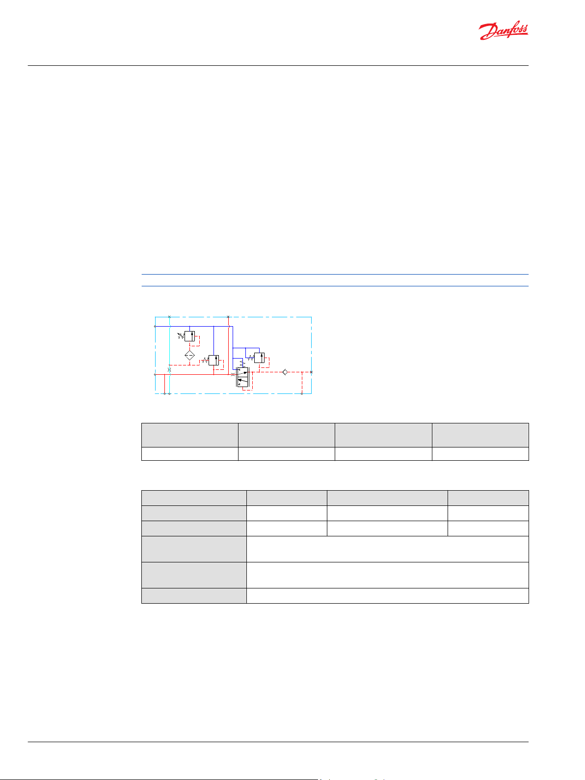
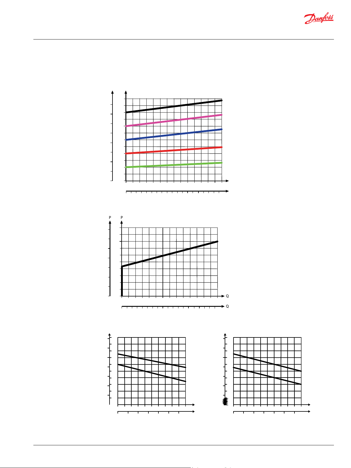
Theoretical Performance Graphs
Integrated LS pressure relief valve characteristics
Neutral by-pass pressure drop characteristics
Pilot pressure reduction valve characteristics
20 | © Danfoss | January 2022 BC290860493426en-000301
Page 21
Technical Information
PVG-EX 32/128/256 Proportional Valve Group
PVG-EX 32
Part numbers for Open Center PVP with PPRV
Part number Actuation P-port T-port LS-port M-port Pp-port T0-port Mounting
1
11008849
11008851
11072195
157B5010
157B5110
157B5130
157B5180
157B5190
157B5210
157B5310
157B5312
157B5330
157B5380
157B5390
11101194
11013317
11020964
11087590
11090453
11119429
11124966
11130941
11196947
11225941
157B5135
157B5904
157B5923
157B5926
157B5934
157B5943
157B5954
157B5960
157B5977
11101194
1
Dampened LS response
2
Pressure adjustment spool with check valve
3
Internal T0 connection
4
Low flow pressure adjustment spool
PVE G3/4” G3/4” G1/4” G1/4” - - M8
1
PVH/PVHC G3/4” G3/4” G1/4” G1/4” G1/4” - M8
PVE M27x2 M27x2 M14x1.5 M14x1.5 - M14x1.5 M8
PVE G1/2” G3/4” G1/4” G1/4” - - M8
PVE G3/4” G3/4” G1/4” G1/4” - - M8
PVE G3/4” G3/4” G1/4” G1/4” G1/4” G1/4” M8
PVE G3/4” G3/4” G1/4” G1/4” G1/4” - M8
PVH/PVHC G3/4” G3/4” G1/4” G1/4” G1/4” - M8
PVE 7/8-14 UNF 1 1/16-12 UNF 1/2-20 UNF 1/2-20 UNF - - 5/16-18 UNC
PVE 1 1/16-12 UNF 1 1/16-12 UNF 1/2-20 UNF 1/2-20 UNF - - 5/16-18 UNC
PVE 1 1/16-12 UNF 1 1/16-12 UNF 1/2-20 UNF 1/2-20 UNF - - 5/16-18 UNC
PVE 1 1/16-12 UNF 1 1/16-12 UNF 1/2-20 UNF 1/2-20 UNF 1/2-20 UNF - 5/16-18 UNC
PVE 1 1/16-12 UNF 1 1/16-12 UNF 9/16-18 UNF 9/16-18 UNF 9/16-18 UNF - 5/16-18 UNC
PVH/PVHC 1 1/16-12 UNF 1 1/16-12 UNF 9/16-18 UNF 9/16-18 UNF 9/16-18 UNF - 5/16-18 UNC
PVE
M22x1.5
M22x1.5 M12x1.5 M10x1 - M16x1.5 M8
M16x1.5 (P2)
1
PVE G3/4 G3/4 G1/4 G1/4 G1/4 G1/4 M8
PVE 1 1/16-12 UNF 1 1/16-12 UNF 1/2-20 UNF 1/2-20 UNF - - M8
1
PVH/PVHC G3/4 G3/4 G1/4 G1/4 G1/4 - M8
PVE JIS 3/4 JIS 3/4 JIS 1/4 JIS 1/4 JIS 1/4 JIS 1/4 M8
2
PVE G3/4 G3/4 G1/4 G1/4 G1/4 - M8
PVH/PVHC G3/4 G3/4 G1/4 G1/4 G1/4 - M8
2
PVE 1 1/16-12 UNF 1 1/16-12 UNF 9/16-18 UNF 9/16-18 UNF 9/16-18 UNF - 5/16-18 UNC
PVE G3/4 G3/4 G1/4 G1/4 - G1/4 M8
PVE 1 1/16-12 UNF 1 1/16-12 UNF 9/16-18 UNF 9/16-18 UNF 9/16-18 UNF 9/16-18
UNF
3
PVE G3/4 G3/4 G1/4 G1/4 G1/4 G1/4 M8
2
PVE G3/4 G3/4 G1/4 G1/4 G1/4 - M8
PVE JIS 1/2 JIS 3/4 JIS 1/4 JIS 1/4 - - M8
PVE JIS 3/4 JIS 3/4 JIS 1/4 JIS 1/4 - - M8
PVE G3/4 G3/4 G1/4 G1/4 - - M8
2
PVH/PVHC G3/4 G3/4 G1/4 G1/4 G1/4 - M8
PVE G3/4 G3/4 G1/4 G1/4 G1/4 - M8
PVE 1 1/16-12 UNF 1 1/16-12 UNF 9/16-18 UNF 9/16-18 UNF - 9/16-18
UNF
1,4
PVE G3/4 G3/4 G1/4 G1/4 - - M8
PVE M22 x 1.5 M22 x 1.5 M12 x 1.5 M10 x 1 - M16 x 1.5 M8
5/16-18 UNC
5/16-18 UNF
©
Danfoss | January 2022 BC290860493426en-000301 | 21
Page 22
LS
P
Pp
M
HPCO
Technical Information
PVG-EX 32/128/256 Proportional Valve Group
PVG-EX 32
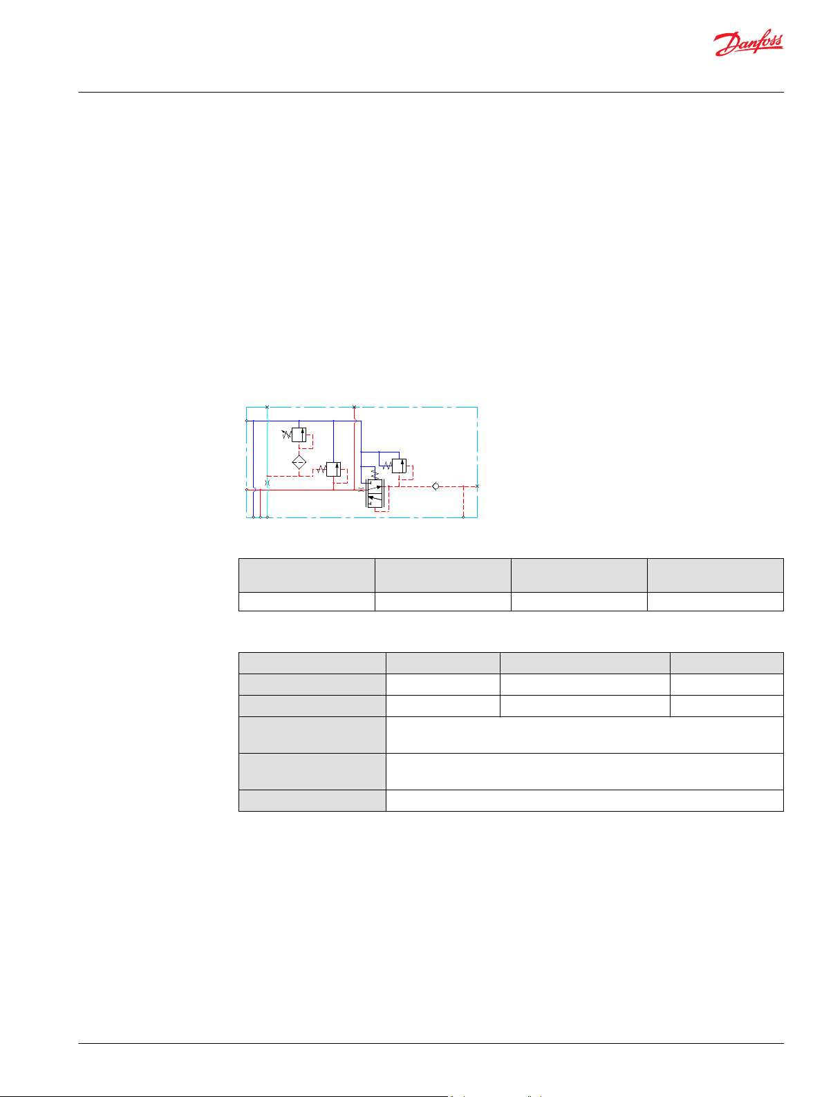
Open center PVP with HPCO and PVE PPRV
The Open Center PVP inlet with integrated High Pressure Carry Over (HPCO) functionality is intended for
use with fixed displacement pumps in applications where one pump supply for multiple hydraulic
subsystems is desired.
The integrated HPCO functionality guides the excess flow of the PVG-EX 32 valve group to the external
hydraulic subsystem(s), giving priority to the PVG-EX 32 work functions.
The Open Center PVP with HPCO and PVE PPRV features:
Integrated LS pressure relief valve
•
Threaded ports for P/T/LS/HPCO and M measuring gauge
•
Integrated pilot pressure reducing valve (PPRV) for PVE
•
Optional T0 facility and external T0 port
•
Optional external pilot pressure port (Pp)
•
Only applicable with PVST end plates with separate T-port due to blocked T-lines for HPCO functionality.
Open Center PVP with HPCO, PVE PPRV schematic
Technical specification for PVP
Max. P-port continuous Max. P-port intermittent Max. T-port static/
dynamic
350 [5076 psi] 400 bar [5800 psi] 25/40 bar [365/580 psi] 140 l/min [37 US gal/min]
Max. rated flow
Technical specification
Parameter Minimum Recommended range Maximum
Fluid temperature
Fluid viscosity
Fluid cleanliness
(mechanical activation)
Fluid cleanliness
(PVE activation)
Operating temperature
-30°C [-22°F] 30 to 60°C [86 to 140°F] 90° [194°F]
4 mm2/s [39 SUS] 12 to 75 mm2/s [65 to 347 SUS] 460 mm2/s [2128 SUS]
23/19/16 (according to ISO 4406)
18/16/13 (according to ISO 4406)
Ambient: -30 to 60°C [-22 to 140°F]
22 | © Danfoss | January 2022 BC290860493426en-000301
Page 23
[l/min]
[US gal/min]
200
150
100
50
20
40
60
80
100
120
140
Q
300
250
P
P
2000
1000
0
0
0
204 8
28
24
32
36
12
16
0
3000
4000
[psi] Q(bar)
(l/min)
[US gal/min]
20
20
40
60 80
100
120
140
16
12
8
4
160
80
0
0
0
240
[psi] (bar)
4
8
12
16
20
24
28
32
36
0
1 2 3 4 5
[l/min]
[US gal/min]
0.2
0.4 0.6 0.8
1.0
1.2
20
16
12
8
4
0
Q
P
240
160
80
0
0
[psi] [bar]
0
Q
Max.
Min.
280
200
120
40
2
18
14
10
6
1 2 3 4 5
[l/min]
[US gal/min]
0.2
0.4
0.6 0.8 1.0 1.2
30
26
22
18
14
0
Q
P
440
360
280
0
0
[psi] [bar]
0
Q
Max.
Min.
480
400
320
240
12
28
24
20
16
PVE PVH/PVHC
Technical Information
PVG-EX 32/128/256 Proportional Valve Group
PVG-EX 32
Theoretical Performance Graphs
Integrated LS pressure relief valve characteristics
©
Danfoss | January 2022 BC290860493426en-000301 | 23
Neutral by-pass pressure drop characteristics
Pilot pressure reduction valve characteristics
Page 24
Technical Information
PVG-EX 32/128/256 Proportional Valve Group
PVG-EX 32
Part numbers for OC PVP (HPCO and PPRV)
Part number P-port HPCO-port LS-port M-port Pp-port T0-port Mounting
157B5140
157B5340
157B5961
11101195
G3/4” G3/4" G1/4” G1/4” G1/4” G1/4” M8
1 1/16-12 UNF 1 1/16-12
M27x2 M27x2 M14x1.5 M14x1.5 – M14x1.5 M8
M22x1.5
M16x1.5 (P2)
UNF
M22x1.5 M12x1.5 M10x1 – M16x1.5 M8
1/2-20 UNF 1/2-20 UNF 1/2-20 UNF 1/2-20 UNF 5/16-18 UNC
24 | © Danfoss | January 2022 BC290860493426en-000301
Page 25
LS
T
P
M
Technical Information
PVG-EX 32/128/256 Proportional Valve Group
PVG-EX 32
Closed Center PVP
The basic Closed Center PVP inlet is intended for use with variable displacement pumps in applications
where a valve group with mechanically controlled work sections is desired, or where the pilot pressure to
the valve group is supplied externally.
The Closed Center PVP features:
Integrated LS pressure relief valve
•
Threaded ports for P/T/LS and M measuring gauge
•
Optional T0 facility and external T0 port
•
Closed center PVP schematic
Technical specification for PVP
Max. P-port continuous Max. P-port intermittent Max. T-port static/
dynamic
350 [5076 psi] 400 bar [5800 psi] 25/40 bar [365/580 psi] 140 l/min [37 US gal/min]
Max. rated flow
Technical specification
Parameter Minimum Recommended range Maximum
Fluid temperature
Fluid viscosity
Fluid cleanliness
(mechanical activation)
Fluid cleanliness
(PVE activation)
Operating temperature
-30°C [-22°F] 30 to 60°C [86 to 140°F] 90° [194°F]
4 mm2/s [39 SUS] 12 to 75 mm2/s [65 to 347 SUS] 460 mm2/s [2128 SUS]
23/19/16 (according to ISO 4406)
18/16/13 (according to ISO 4406)
Ambient: -30 to 60°C [-22 to 140°F]
©
Danfoss | January 2022 BC290860493426en-000301 | 25
Page 26
[l/min]
[US gal/min]
200
150
100
50
20
40
60
80
100
120
140
Q
300
250
P
P
2000
1000
0
0
0
204 8
28
24
32
36
12
16
0
3000
4000
[psi] Q(bar)
Technical Information
PVG-EX 32/128/256 Proportional Valve Group
PVG-EX 32
Theoretical Performance Graphs
Integrated LS pressure relief valve characteristics
Part numbers for Closed Center PVP
Part number P-port T-port LS-port
(LS1**)
11030683 G3/4 G3/4 G1/4 (G1/4) G1/4 G1/4 M8
157B5001 G1/2 G3/4 G1/4 G1/4 - M8
157B5101 G3/4 G3/4 G1/4 G1/4 - M8
157B5201 7/8-14 UNF 1 1/16-12 UNF 1/2-20 UNF 1/2-20 UNF -- 5/16-18 UNC
157B5301 1 1/16-12 UNF 1 1/16-12 UNF 1/2-20 UNF 1/2-20 UNF - 5/16-18 UNC
15B5907 1 1/16-12 UNF 1 1/16-12 UNF 1/2-20 UNF 1/2-20 UNF - M8
157B5922 JIS 1/2 JIS 3/4 JIS 1/4 JIS 1/4 - M8
157B5927 JIS 3/4 JIS 3/4 JIS 1/4 JIS 1/4 - M8
157B5946 G1/2 G3/4 G1/4 (G1/8) G1/4 - M8
**
LS1 is an extra LS-port
M-port T0-port Mounting
26 | © Danfoss | January 2022 BC290860493426en-000301
Page 27
LS
T
P
M
Pp
Technical Information
PVG-EX 32/128/256 Proportional Valve Group
PVG-EX 32
Closed Center PVP with PPRV
The Closed Center PVP inlet with integrated pilot pressure reduction valve (PPRV) is intended for use with
variable displacement pumps in applications where a valve group with electro-hydraulic or hydraulically
controlled work sections is desired.
The Closed Center PVP with PPRV features:
Integrated LS pressure relief valve
•
Threaded ports for P/T/LS and M measuring gauge
•
Integrated pilot pressure reducing valve (PPRV) for PVE or PVH/PVHC
•
Optional T0 facility and external T0 port
•
Closed center PVP with PPRV schematic
Technical specification for PVP
Max. P-port continuous Max. P-port intermittent Max. T-port static/
dynamic
350 [5076 psi] 400 bar [5800 psi] 25/40 bar [365/580 psi] 140 l/min [37 US gal/min]
Max. rated flow
Technical specification
Parameter Minimum Recommended range Maximum
Fluid temperature
Fluid viscosity
Fluid cleanliness
(mechanical activation)
Fluid cleanliness
(PVE activation)
Operating temperature
-30°C [-22°F] 30 to 60°C [86 to 140°F] 90° [194°F]
4 mm2/s [39 SUS] 12 to 75 mm2/s [65 to 347 SUS] 460 mm2/s [2128 SUS]
23/19/16 (according to ISO 4406)
18/16/13 (according to ISO 4406)
Ambient: -30 to 60°C [-22 to 140°F]
©
Danfoss | January 2022 BC290860493426en-000301 | 27
Page 28
[l/min]
[US gal/min]
200
150
100
50
20
40
60
80
100
120
140
Q
300
250
P
P
2000
1000
0
0
0
204 8
28
24
32
36
12
16
0
3000
4000
[psi] Q(bar)
1 2 3 4 5
[l/min]
[US gal/min]
0.2
0.4 0.6 0.8
1.0
1.2
20
16
12
8
4
0
Q
P
240
160
80
0
0
[psi] [bar]
0
Q
Max.
Min.
280
200
120
40
2
18
14
10
6
1 2 3 4 5
[l/min]
[US gal/min]
0.2
0.4
0.6 0.8 1.0 1.2
30
26
22
18
14
0
Q
P
440
360
280
0
0
[psi] [bar]
0
Q
Max.
Min.
480
400
320
240
12
28
24
20
16
PVE PVH/PVHC
Technical Information
PVG-EX 32/128/256 Proportional Valve Group
PVG-EX 32
Theoretical Performance Graphs
Integrated LS pressure relief valve characteristics
Pilot pressure reduction valve characteristics
Part numbers for Closed Center PVP with PPRV
Part number Actuation P-port T-port LS-port (LS1**M-port Pp-port T0-port Mounting
11051802
157B5011
157B5111
157B5131
157B5181
157B5191
157B5211
157B5311
157B5331
157B5381
157B5391
**
LS1 is an extra LS-port
28 | © Danfoss | January 2022 BC290860493426en-000301
PVH/PVHC 1 1/16-12 UNF 1 1/16-12 UNF 1/2-20 UNF 1/2-20 UNF 1/2-20 UNF 1/2-20 UNF 5/16-18 UNC
PVE G1/2” G3/4” G1/4” G1/4” - - M8
PVE G3/4” G3/4” G1/4” G1/4” - - M8
PVE G3/4” G3/4” G1/4” G1/4” G1/4” G1/4” M8
PVE G3/4” G3/4” G1/4” G1/4” G1/4” - M8
PVH/PVHC G3/4” G3/4” G1/4” G1/4” G1/4” - M8
PVE 7/8-14 UNF 1 1/16-12 UNF 1/2-20 UNF 1/2-20 UNF - - 5/16-18 UNC
PVE 1 1/16-12 UNF 1 1/16-12 UNF 1/2-20 UNF 1/2-20 UNF - - 5/16-18 UNC
PVE 1 1/16-12 UNF 1 1/16-12 UNF 1/2-20 UNF 1/2-20 UNF 1/2-20 UNF 1/2-20 UNF 5/16-18 UNC
PVE 1 1/16-12 UNF 1 1/16-12 UNF 9/16-18 UNF 9/16-18 UNF 9/16-18 UNF - 5/16-18 UNC
PVH/PVHC 1 1/16-12 UNF 1 1/16-12 UNF 9/16-18 UNF 9/16-18 UNF 9/16-18 UNF - 5/16-18 UNC
Page 29
T
LS
P
M
Technical Information
PVG-EX 32/128/256 Proportional Valve Group
PVG-EX 32
All modules can be manually activated with the PVM actuation.
Closed center PVPV
The Closed Center PVPV inlet is intended for use with variable displacement pumps in applications where
a valve group with mechanical controlled work sections is desired.
The Closed center PVPV features:
•
Optional T0 facility and port
•
Threaded ports for P/T/LS and M measuring gauge
•
Optional additional threaded ports for P2, T2, and T02
PVPV Schematic
Technical specification for PVP
Max. P-port continuous Max. P-port intermittent Max. T-port static/
dynamic
350 [5076 psi] 400 bar [5800 psi] 25/40 bar [365/580 psi] 140 l/min [37 US gal/min]
Max. rated flow
Technical specification
Parameter Minimum Recommended range Maximum
Fluid temperature
Fluid viscosity
Fluid cleanliness
(mechanical activation)
Fluid cleanliness
(PVE activation)
Operating temperature
-30°C [-22°F] 30 to 60°C [86 to 140°F] 90° [194°F]
4 mm2/s [39 SUS] 12 to 75 mm2/s [65 to 347 SUS] 460 mm2/s [2128 SUS]
23/19/16 (according to ISO 4406)
18/16/13 (according to ISO 4406)
Ambient: -30 to 60°C [-22 to 140°F]
Part numbers for Closed Center PVPV
Part number P-port (P2) T-port (T2) LS-port M-port T0-port (T02) Mounting
11055758
11067570 M27x2.0 M33x2.0 M14x1.5 M14x1.5 - M8
M27x2.0
(M27x2.0)
M27x2.0
(M14x1.5)
M14x1.5 M14x1.5 M14x1.5
(M14x1.5)
M8
©
Danfoss | January 2022 BC290860493426en-000301 | 29
Page 30
T
LS
P
M
1 2 3 4 5
[l/min]
[US gal/min]
0.2
0.4 0.6 0.8
1.0
1.2
20
16
12
8
4
0
Q
P
240
160
80
0
0
[psi] [bar]
0
Q
Max.
Min.
280
200
120
40
2
18
14
10
6
1 2 3 4 5
[l/min]
[US gal/min]
0.2
0.4
0.6 0.8 1.0 1.2
30
26
22
18
14
0
Q
P
440
360
280
0
0
[psi] [bar]
0
Q
Max.
Min.
480
400
320
240
12
28
24
20
16
PVE PVH/PVHC
Technical Information
PVG-EX 32/128/256 Proportional Valve Group
PVG-EX 32
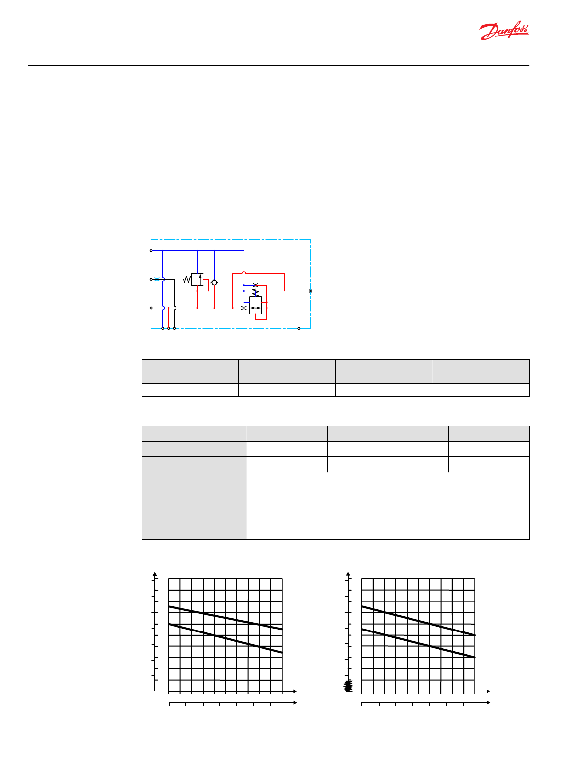
Closed center PVPV with PPRV
The Closed Center PVPV inlet with integrated pilot pressure reduction valve (PPRV) is intended for use
with variable displacement pumps in applications where a valve group with electro-hydraulic or
hydraulically controlled work sections is desired.
The Closed Center PVPV with PPRV features:
Optional shock/anti-cavitation valve facility (PVLP)
•
Threaded ports for P/T/LS and M measuring gauge
•
Integrated pilot pressure reducing valve (PPRV) for PVE or PVH/PVHC
•
Hydraulic schematic
Technical specification for PVP
Max. P-port continuous Max. P-port intermittent Max. T-port static/
dynamic
350 [5076 psi] 400 bar [5800 psi] 25/40 bar [365/580 psi] 140 l/min [37 US gal/min]
Max. rated flow
Technical specification
Parameter Minimum Recommended range Maximum
Fluid temperature
Fluid viscosity
Fluid cleanliness
-30°C [-22°F] 30 to 60°C [86 to 140°F] 90° [194°F]
4 mm2/s [39 SUS] 12 to 75 mm2/s [65 to 347 SUS] 460 mm2/s [2128 SUS]
23/19/16 (according to ISO 4406)
(mechanical activation)
Fluid cleanliness
18/16/13 (according to ISO 4406)
(PVE activation)
Operating temperature
Ambient: -30 to 60°C [-22 to 140°F]
Pilot pressure reduction valve characteristics
30 | © Danfoss | January 2022 BC290860493426en-000301
Page 31

Technical Information
PVG-EX 32/128/256 Proportional Valve Group
PVG-EX 32
Part numbers for Closed Center PVPV with PPRV
Part number Actuator P-port T-port (T2) LS-port M-port Pp-port
T0-port
(T02)
11012350
11003806 M27x2.0
11008854
1
2
M27x2.0 M33x2.0 M14x1.5 M14x1.5 G1/4 - M8 -
M27x2.0
(M14x1.5)
M14x1.5 M14x1.5 G1/4
M14x1.5
(M14x1.5)
G1 G1 G1/4 G1/4 G1/4 - M8 Yes
11124107 1 5/16-12 1 1/16-12 9/16-18 9/16-18 G1/4 - M8 Yes
11196949 G1 G1 - - - - M8 Yes
157B5911 1 5/16-12 1 5/16-12 9/16-18 9/16-18 G1/4 - 5/16-18 -
PVE
157B5913 1 5/16-12 1 5/16-12 9/16-18 9/16-18 G1/4 - 5/16-18 Yes
157B5938 G1 G1 G1/4 G1/4 G1/4 - M8 157B5941 G1 G1 G1/4 G1/4 G1/4 - M8 Yes
157B5948
157B5973
3
4
G1 G1 G1/4 G1/4 G1/4 - M8 Yes
G1 G1 G1/4 G1/4 G1/4 - M8 Yes
157B5978 M27x2.0 M33x2.0 M14x1.5 M14x1.5 G1/4 - M8 11008856
11051803 1 5/16-12 1 5/16-12 9/16-18 9/16-18 G1/4 - 5/16-18 Yes
157B5916 1 5/16-12 1 5/16-12 9/16-18 9/16-18 G1/4 - 5/16-18 -
PVH/PVHC
G1 G1 G1/4 G1/4 G1/4 - M8 Yes
157B5963 1 1/16-12 1 1/16-12 7/16-20 - M18x1.5 9/16-18 M8 -
1
No LS-orifice
2
Internal T0 connection
3
0.4 mm hole in the pilot reduction cone (standard 0.8 mm)
4
HPCO-facility
Mounting PVLP
M8 -
All modules can be manually activated with the PVM actuation.
©
Danfoss | January 2022 BC290860493426en-000301 | 31
Page 32

T
LS
P
M
Pp
Technical Information
PVG-EX 32/128/256 Proportional Valve Group
PVG-EX 32
Closed center PVPVM with PPRV
The Closed Center PVPVM mid-inlet module with integrated pilot pressure reduction valve (PPRV) is
intended for use with variable displacement pumps in applications where a valve group with electrohydraulic or hydraulically controlled work sections is desired.
Using a PVPVM module in a valve group requires a 180° degree rotation of the PVG work sections on one
side.
The Closed Center PVPVM with PPRV features:
Optional shock/anti-cavitation valve facility (PVLP)
•
Threaded ports for P/T/LS and M measuring gauge
•
Integrated pilot pressure reducing valve (PPRV) for PVE or PVH/PVHC
•
Hydraulic schematic
Technical specification for PVP
Max. P-port continuous Max. P-port intermittent Max. T-port static/
dynamic
350 [5076 psi] 400 bar [5800 psi] 25/40 bar [365/580 psi] 230 l/min [61 US gal/min]
Max. rated flow
Technical specification
Parameter Minimum Recommended range Maximum
Fluid temperature
Fluid viscosity
Fluid cleanliness
(mechanical activation)
Fluid cleanliness
(PVE activation)
Operating temperature
-30°C [-22°F] 30 to 60°C [86 to 140°F] 90° [194°F]
4 mm2/s [39 SUS] 12 to 75 mm2/s [65 to 347 SUS] 460 mm2/s [2128 SUS]
23/19/16 (according to ISO 4406)
18/16/13 (according to ISO 4406)
Ambient: -30 to 60°C [-22 to 140°F]
32 | © Danfoss | January 2022 BC290860493426en-000301
Page 33

1 2 3 4 5
[l/min]
[US gal/min]
0.2
0.4 0.6 0.8
1.0
1.2
20
16
12
8
4
0
Q
P
240
160
80
0
0
[psi] [bar]
0
Q
Max.
Min.
280
200
120
40
2
18
14
10
6
1 2 3 4 5
[l/min]
[US gal/min]
0.2
0.4
0.6 0.8 1.0 1.2
30
26
22
18
14
0
Q
P
440
360
280
0
0
[psi] [bar]
0
Q
Max.
Min.
480
400
320
240
12
28
24
20
16
PVE PVH/PVHC
Technical Information
PVG-EX 32/128/256 Proportional Valve Group
PVG-EX 32
Pilot pressure reduction valve characteristics
Part numbers for Closed Center PVPVM with PPRV
Part number Actuator P-port T-port LS-port M-port Pp-port Mounting PVLP
157B5914
157B5937 G1 G1 G1/4 G1/4 G1/4 M8 157B5940 G1 G1 G1/4 G1/4 G1/4 M8 Yes
11083156
157B5912 1 5/16-12
157B5986 G1 G1 G1/4 G1/4 G1/4 M8 Yes
PVE
PVH/PVHC
1 5/16-12
UNF
1 1/16-12
UNF
UNF
1 5/16-12
UNF
1 1/16-12
UNF
1 5/16-12
UNF
9/16-18 UNF 9/16-18 UNF G1/4 5/16-18 UNC Yes
9/16-18 UNF 9/16-18 UNF G1/4 5/16-18 UNC Yes
9/16-18 UNF 9/16-18 UNF G1/4 5/16-18 UNC -
©
Danfoss | January 2022 BC290860493426en-000301 | 33
All modules can be manually activated with the PVM actuation.
Page 34

LS
T
P
M
OC
CC
Technical Information
PVG-EX 32/128/256 Proportional Valve Group
PVG-EX 32
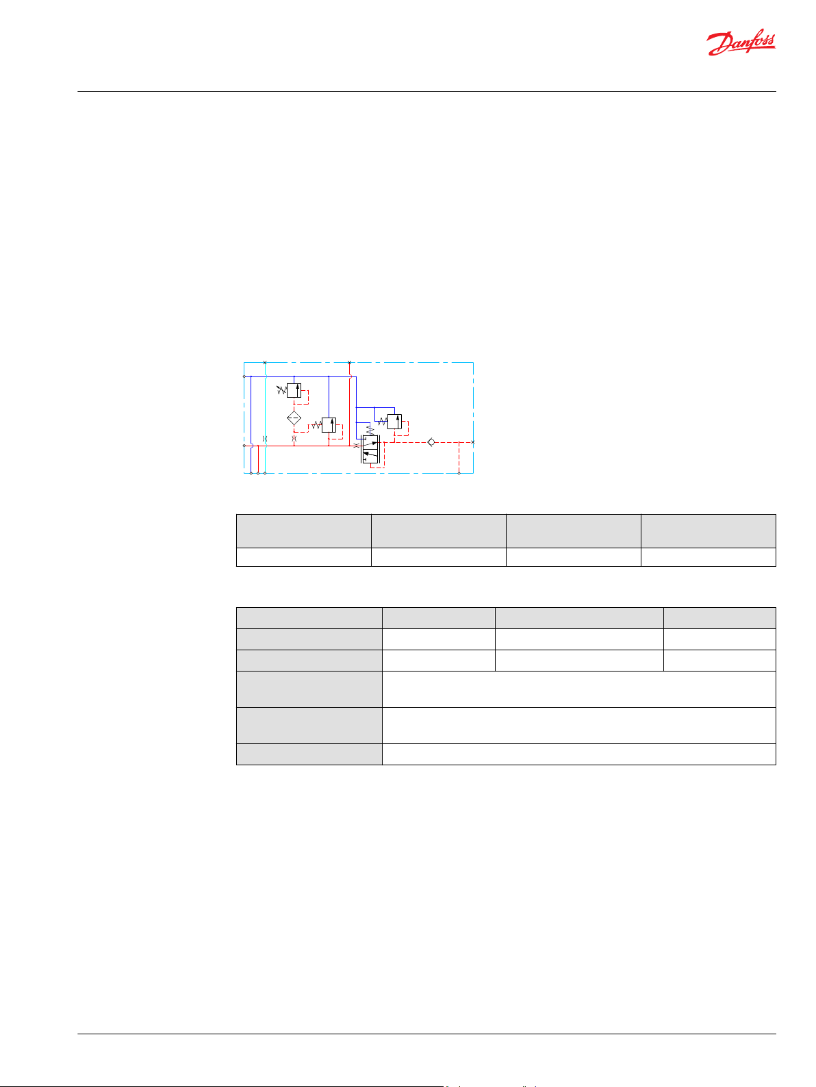
Open/Closed center PVP with PPRV
The Open Center/Closed Center PVP with integrated pilot pressure reduction valve (PPRV) is intended for
use with fixed or variable displacement pumps in applications where the application manufacturer does
not determine the pump type.
The modules allow an easy switch between Open Center and Closed Center configuration by means of an
external hexagon selector key. Variants also feature an LS boost functionality, increasing the LS pressure
to the pump LS regulator with a constant 6 bar, compensating for potential LS bleed-off and leakage.
The Open/closed center PVPV with PPRV features:
Integrated OC/CC selector
•
Integrated LS pressure relief valve
•
Threaded ports for P/T/LS and M measuring gauge
•
Integrated pilot pressure reducing valve (PPRV) for PVE or PVH/PVHC
•
Optional LS boost functionality
•
Hydraulic schematic
Technical specification for PVP
Max. P-port continuous Max. P-port intermittent Max. T-port static/
dynamic
350 [5076 psi] 400 bar [5800 psi] 25/40 bar [365/580 psi] 140 l/min [37 US gal/min]
Max. rated flow
Technical specification
Parameter Minimum Recommended range Maximum
Fluid temperature
Fluid viscosity
Fluid cleanliness
(mechanical activation)
Fluid cleanliness
(PVE activation)
Operating temperature
-30°C [-22°F] 30 to 60°C [86 to 140°F] 90° [194°F]
4 mm2/s [39 SUS] 12 to 75 mm2/s [65 to 347 SUS] 460 mm2/s [2128 SUS]
23/19/16 (according to ISO 4406)
18/16/13 (according to ISO 4406)
Ambient: -30 to 60°C [-22 to 140°F]
34 | © Danfoss | January 2022 BC290860493426en-000301
Page 35

[l/min]
[US gal/min]
200
150
100
50
20
40
60
80
100
120
140
Q
300
250
P
P
2000
1000
0
0
0
204 8
28
24
32
36
12
16
0
3000
4000
[psi] Q(bar)
(l/min)
[US gal/min]
20
20
40
60 80
100
120
140
16
12
8
4
160
80
0
0
0
240
[psi] (bar)
4
8
12
16
20
24
28
32
36
0
1 2 3 4 5
[l/min]
[US gal/min]
0.2
0.4 0.6 0.8
1.0
1.2
20
16
12
8
4
0
Q
P
240
160
80
0
0
[psi] [bar]
0
Q
Max.
Min.
280
200
120
40
2
18
14
10
6
1 2 3 4 5
[l/min]
[US gal/min]
0.2
0.4
0.6 0.8 1.0 1.2
30
26
22
18
14
0
Q
P
440
360
280
0
0
[psi] [bar]
0
Q
Max.
Min.
480
400
320
240
12
28
24
20
16
PVE PVH/PVHC
Technical Information
PVG-EX 32/128/256 Proportional Valve Group
PVG-EX 32
Theoretical Performance Graphs
Integrated LS pressure relief valve characteristics
©
Danfoss | January 2022 BC290860493426en-000301 | 35
Neutral by-pass pressure drop characteristics
Pilot pressure reduction valve characteristics
Page 36

Technical Information
PVG-EX 32/128/256 Proportional Valve Group
PVG-EX 32
Part numbers for Open/Closed Center PVP with PPRV
Part number Actuation P-port T-port LS-port (LS1**) M-port T0-port Mounting LS Boost
11093273 PVE G3/4 G3/4 - G1/4 - M8 Yes
11119094 PVE G3/4 G3/4 - G1/4 - M8 11119095 PVE 1 1/16-12 UNF 1 1/16-12 UNF 1/2-20 UNF 1/2-20 UNF - M8 11131344 PVH/PVHC G3/4 G3/4 - G1/4 - M8 Yes
111686081PVE G3/4 G3/4 - G1/4 - M8 Yes
**
LS1 is an extra LS-port
1
Dampened LS response
All modules can be manually activated with the PVM actuation.
36 | © Danfoss | January 2022 BC290860493426en-000301
Page 37

T
P
Technical Information
PVG-EX 32/128/256 Proportional Valve Group
PVG-EX 32
Open/Closed center PVPM
The Open Center/Closed Center PVPM mid-inlet acts as a simple manifold and is intended for use with
fixed or variable displacement pumps. The PVPM features no logic other than a PVLP shock/anticavitation valve facility for pressure peak protection and anti-cavitation prevention.
The PVPM module must be configured together with an Open Center PVP module for fixed
displacement pumps and for variable displacement pumps can be configured together with a PVSI
start plate or a Closed Center PVP/PVPV module.
The Open center/closed center PVPM features:
Integrated shock/anti-cavitation valve facility (PVLP)
•
Threaded ports for P/T
•
Pilot pressure and T0 lines through module
•
Hydraulic schematic
Technical specification for PVP
Max. P-port continuous Max. P-port intermittent Max. T-port static/
dynamic
350 [5076 psi] 400 bar [5800 psi] 25/40 bar [365/580 psi] 230 l/min [61 US gal/min]
Max. rated flow
Technical specification
Parameter Minimum Recommended range Maximum
Fluid temperature
Fluid viscosity
Fluid cleanliness
(mechanical activation)
Fluid cleanliness
(PVE activation)
Operating temperature
-30°C [-22°F] 30 to 60°C [86 to 140°F] 90° [194°F]
4 mm2/s [39 SUS] 12 to 75 mm2/s [65 to 347 SUS] 460 mm2/s [2128 SUS]
23/19/16 (according to ISO 4406)
18/16/13 (according to ISO 4406)
Ambient: -30 to 60°C [-22 to 140°F]
Part numbers for Open Center/Closed Center PVPM
Part number P-, T-port Mounting PVLP
11093682
11093684
1 5/16-12 UN 5/16-18 UNC Yes
G1” M8 Yes
©
Danfoss | January 2022 BC290860493426en-000301 | 37
Page 38

Technical Information
PVG-EX 32/128/256 Proportional Valve Group
PVG-EX 32
PVP Inlet Module Accessories
The generic PVP inlet module accessory platform includes the PVPX Electrical LS pressure unloading
valve, External pilot pressure adapters PVPC with or without check valve for all Open Center PVP with
PPRV.
PVPC without Check Valve on page 39
•
PVPC with Check Valve on page 41
•
38 | © Danfoss | January 2022 BC290860493426en-000301
Page 39

Technical Information
PVG-EX 32/128/256 Proportional Valve Group
PVG-EX 32
PVPC without Check Valve
The PVPC external pilot pressure adapter without check valve is an accessory in the M-port available for
PVP inlet modules with integrated pilot pressure reduction valve (PPRV).
The PVPC without check valve cuts off the integrated PPRV to the PVE or PVH/PVHC in the valve group
and enables an external pilot pressure supply through the PVPC adapter.
PVPC without Check Valve
©
Danfoss | January 2022 BC290860493426en-000301 | 39
Page 40

LS
T
P
M
A
B
Technical Information
PVG-EX 32/128/256 Proportional Valve Group
PVG-EX 32
PVP with PVPC without check valve schematic
One application example for the PVPC without check valve is where it is a wanted feature to supply the
valve group with oil from a manually operated emergency pump without directing oil flow to the PPRV.
When the main pump is running in its normal operation mode, the oil is directed through the PVPC
adapter via the PPRV to the PVE electrical actuators.
When the main pump flow fails, the external shuttle valve ensures that the oil flow from the manually
operated emergency pump is used to pilot open the over-center valve and lower the load. The load is
only possible to lower when using the mechanical operating lever of the PVG work sections.
Part numbers for Open Center/Closed Center PVPM
Part number 157B5400 158X1000
Thread G1/2” 1/2-20 UNF
40 | © Danfoss | January 2022 BC290860493426en-000301
Page 41

LS
T
P
M
A
B
Technical Information
PVG-EX 32/128/256 Proportional Valve Group
PVG-EX 32
PVPC with Check Valve
The PVPC external pilot pressure adapter with check valve is an accessory in the M-port available for PVP
inlet modules with integrated pilot pressure reduction valve (PPRV).
The PVPC with check valve enables an external pilot pressure supply through the PVPC adapter and the
PPRV, while also allowing the main pump to supply the PPRV through the P-gallery as a standard Open
Center PVP with PPRV.
PVPC with Check Valve
PVP with PVPC with check valve schematic
One application example for the PVPC with check valve is where it is a wanted feature to operate the
valve group by means of the PVE electrical actuators without pump flow.
©
Danfoss | January 2022 BC290860493426en-000301 | 41
Page 42

114 [4.49]
109 [4.29]
110 [4.33]
22.5 [0.89]
48 [1.89]
49 [1.93]
P
P
Technical Information
PVG-EX 32/128/256 Proportional Valve Group
PVG-EX 32
When the external solenoid valve is opened, oil from the pressure side of the cylinder is fed via the PVPC
through the PPRV to act as the pilot supply for the PVE electrical actuators. This means that it is possible
to lower a load by means of the PVE electrical actuators without starting the pump.
The built-in check valve prevents the oil from flowing via the pressure adjustment spool to tank. With the
pump functioning normally the external solenoid valve is closed to ensure that the load is not lowered
due to the pilot supply oil flow requirement of approximately 1 l/min [0.25 US gal/min].
With a Closed Center PVP the external pilot oil supply can be connected to the pressure gauge
connection without the use of a PVPC plug.
Part numbers for Open Center/Closed Center PVPM
Part number 157B5600 157B5700
Thread G1/2” 1/2-20 UNF
PVB Basic Modules
The PVG-EX 32 PVB basic modules, also referred to as work sections, are the interface between the PVGEX 32 proportional valve group and the work function such as a cylinder or a motor.
PVB Basic Module PVB 32 dimensions
Weight: 3.05 kg [6.73 lb]
Uncompensated PVB schematic symbol
Compensated PVB schematic symbol
The PVB basic module variants are based on a generic platform with a selection of additional features,
enabling you to tailor the PVB to suit the demands of any hydraulic system. The generic PVB basic
module platform includes the following main variants:
•
Uncompensated PVB on page 44
•
Uncompensated PVB with load drop check valve on page 47
•
Uncompensated PVBZ with POC on page 50
•
Compensated PVB on page 51
42 | © Danfoss | January 2022 BC290860493426en-000301
Page 43

Technical Information
PVG-EX 32/128/256 Proportional Valve Group
PVG-EX 32
•
Dampened Compensated PVB on page 54
•
Dampened compensated PVB with LS A/B on page 57
•
Compensated PVB with LS A/B on page 60
•
Compensated high flow PVB on page 64
•
Compensated high flow PVB with LS A/B on page 67
•
Compensated PVBZ with POC on page 71
•
Compensated high flow PVBZ with POC on page 73
•
Compensated high flow PVBZ with POC and manifold interface on page 75
©
Danfoss | January 2022 BC290860493426en-000301 | 43
Page 44

A
B
1
0
2
Technical Information
PVG-EX 32/128/256 Proportional Valve Group
PVG-EX 32
Uncompensated PVB
The uncompensated PVB is intended for controlling a work function where the function behavior in
terms of flow and pressures requires independence on the load pressure of other functions used
simultaneously.
The Uncompensated PVB features:
•
Integrated LS shuttle network
•
Optional shock/anti-cavitation valve facility (PVLP)
•
Optional LS
•
Optional T0 facility
Schematic
shuttle valve facility for float spool use
A/B
Technical specification for A/B-port
Max. continuous pressure Max. intermittent pressure Max. rated flow
350 bar [5076 psi]
*
With PVSI end plate. With PVS end plate max. 300 [4351 psi]
**
Intermittent pressure at max. 250,000 cycles of full PVG life time cycles, with PVSI end plate. The maximum
intermittent pressure at max. 250,000 cycles stresses the need to confirm application duty cycle before proceeding
with specification. For further information contact Danfoss Product Application Engineering.
*
420 bar [6090 psi]
**
125 l/min [33 US gal/min]
Technical specification
Parameter Minimum Recommended range Maximum
Fluid temperature
Fluid viscosity
Fluid cleanliness
(mechanical activation)
Fluid cleanliness
(PVE activation)
Operating temperature
-30°C [-22°F] 30 to 60°C [86 to 140°F] 90° [194°F]
4 mm2/s [39 SUS] 12 to 75 mm2/s [65 to 347 SUS] 460 mm2/s [2128 SUS]
23/19/16 (according to ISO 4406)
18/16/13 (according to ISO 4406)
Ambient: -30 to 60°C [-22 to 140°F]
44 | © Danfoss | January 2022 BC290860493426en-000301
Page 45

(l/min)
[US gal/min]
P
Q
Q
(bar)
[psi]
20 40 60 80 100 120 140
5
10 15 20 25 30 35 40 45
400
350
300
250
200
150
100
50
0
5000
4000
3000
2000
1000
0
6000
0
0
5 10 15 20 25 30 35 40 45 50 55 60 65
[l/min]
[US gal/min]
70 75 80
1 2 3 4 5 6 7 8 9 10 11 12 13 14 15 16 17 18 19 20 21
20
18
16
14
12
10
8
6
4
2
0
85 90 95 100
22 23 24 25 26
Q
28
26
24
22
P
P
200
160
120
80
40
0
280
240
320
400
360
0
[psi] [bar]
0
Q
105 110 115 120
27 28 29 30 31
PVLP
PVLA
Technical Information
PVG-EX 32/128/256 Proportional Valve Group
PVG-EX 32
Performance graphs (Theoretical)
PVLP shock valve characteristics
PVLP/PVLA suction valve characteristics
Part numbers for uncompensated PVB
Part number A/B-port PVLP/PVLA LS A/B shuttle T0 facility
157B6000
157B6010
©
Danfoss | January 2022 BC290860493426en-000301 | 45
157B6030
11071832
G1/2"
— — —
— — Yes
Yes — —
Yes Yes —
Page 46

Technical Information
PVG-EX 32/128/256 Proportional Valve Group
PVG-EX 32
Part numbers for uncompensated PVB (continued)
Part number A/B-port PVLP/PVLA LS A/B shuttle T0 facility
157B6400
157B6410
157B6430
7/8–14 UNF
— — —
— — Yes
Yes — —
46 | © Danfoss | January 2022 BC290860493426en-000301
Page 47

A
B
1
0
2
Technical Information
PVG-EX 32/128/256 Proportional Valve Group
PVG-EX 32
Uncompensated PVB with load drop check valve
The uncompensated PVB is intended for controlling a work function where the function behavior in
terms of flow and pressures allows dependency on the load pressure of other functions used
simultaneously. The integrated load drop check valve prevents flow back from work ports influencing
other functions.
The Uncompensated PVB with load drop check valve features:
•
Integrated LS shuttle network
•
Load drop check valve
•
Optional shock/anti-cavitation valve facility (PVLP)
•
Optional LS
•
Optional T0 facility
Schematic
shuttle valve facility for float spool use
A/B
Technical specification for A/B-port
Max. continuous pressure Max. intermittent pressure Max. rated flow
350 bar [5076 psi] 420 bar [6090 psi] 125 l/min [33 US gal/min]
Technical specification
Parameter Minimum Recommended range Maximum
Fluid temperature
Fluid viscosity
Fluid cleanliness
(mechanical activation)
Fluid cleanliness
(PVE activation)
Operating temperature
-30°C [-22°F] 30 to 60°C [86 to 140°F] 90° [194°F]
4 mm2/s [39 SUS] 12 to 75 mm2/s [65 to 347 SUS] 460 mm2/s [2128 SUS]
23/19/16 (according to ISO 4406)
18/16/13 (according to ISO 4406)
Ambient: -30 to 60°C [-22 to 140°F]
©
Danfoss | January 2022 BC290860493426en-000301 | 47
Page 48

(l/min)
[US gal/min]
P
Q
Q
(bar)
[psi]
20 40 60 80 100 120 140
5
10 15 20 25 30 35 40 45
400
350
300
250
200
150
100
50
0
5000
4000
3000
2000
1000
0
6000
0
0
5 10 15 20 25 30 35 40 45 50 55 60 65
[l/min]
[US gal/min]
70 75 80
1 2 3 4 5 6 7 8 9 10 11 12 13 14 15 16 17 18 19 20 21
20
18
16
14
12
10
8
6
4
2
0
85 90 95 100
22 23 24 25 26
Q
28
26
24
22
P
P
200
160
120
80
40
0
280
240
320
400
360
0
[psi] [bar]
0
Q
105 110 115 120
27 28 29 30 31
PVLP
PVLA
Technical Information
PVG-EX 32/128/256 Proportional Valve Group
PVG-EX 32
Performance graphs (Theoretical)
PVLP shock valve characteristics
PVLP/PVLA suction valve characteristics
48 | © Danfoss | January 2022 BC290860493426en-000301
Part numbers for Uncomp. PVB with load drop check valve
Part number A/B-port PVLP/PVLA LS A/B shuttle T0 facility
157B6100
157B6500
157B6110
157B6909
G1/2" — — —
7/8–14 UNF — — —
G1/2" — — Yes
7/8–14 UNF — — Yes
Page 49

Technical Information
PVG-EX 32/128/256 Proportional Valve Group
PVG-EX 32
Part numbers for Uncomp. PVB with load drop check valve (continued)
Part number A/B-port PVLP/PVLA LS A/B shuttle T0 facility
157B6130
157B6530
157B6140
157B6904
157B6136
157B6536
G1/2" Yes — —
7/8–14 UNF Yes — —
G1/2" Yes — Yes
7/8–14 UNF Yes — Yes
G1/2" Yes Yes —
7/8–14 UNF Yes Yes —
©
Danfoss | January 2022 BC290860493426en-000301 | 49
Page 50

1
0
2
A
B
Technical Information
PVG-EX 32/128/256 Proportional Valve Group
PVG-EX 32
Uncompensated PVBZ with POC
The uncompensated PVBZ is intended for controlling a work function where the function behavior in
terms of flow and pressures allows dependency on the load pressure of other functions used
simultaneously.
The Pilot Operated Check valve giving very low leakage will prevent cylinder creep.
The Uncompensated PVBZ with POC features:
Integrated LS shuttle network
•
Integrated POC
•
Optional T0 facility
•
Schematic
Technical specification for A/B-port
Max. continuous pressure Max. intermittent pressure Max. rated flow
350 bar [5076 psi] 420 bar [6090 psi] 125 l/min [33 US gal/min]
Technical specification
Parameter Minimum Recommended range Maximum
Fluid temperature
Fluid viscosity
Fluid cleanliness
(mechanical activation)
Fluid cleanliness
(PVE activation)
Operating temperature
-30°C [-22°F] 30 to 60°C [86 to 140°F] 90° [194°F]
4 mm2/s [39 SUS] 12 to 75 mm2/s [65 to 347 SUS] 460 mm2/s [2128 SUS]
23/19/16 (according to ISO 4406)
18/16/13 (according to ISO 4406)
Ambient: -30 to 60°C [-22 to 140°F]
Part numbers for uncompensated PVBZ with POC
Part number A/B-port POC
157B6051
157B6052
157B6451
157B6452
157B6969
G½"
7/8–14 UNF
None – machined top A-port
B-port
A/B-port
B-port
A/B-port
50 | © Danfoss | January 2022 BC290860493426en-000301
Page 51

A
B
1
0
2
Technical Information
PVG-EX 32/128/256 Proportional Valve Group
PVG-EX 32
Compensated PVB
The compensated PVB is intended for controlling a work function where the function behavior in terms
of flow and pressures requires independence on the load pressure of other functions used
simultaneously.
The Compensated PVB features:
Integrated LS shuttle network
•
Integrated compensator
•
Optional shock/anti-cavitation valve facility (PVLP)
•
Optional T0 facility and external T0 port
•
Compensated PVB schematic
Technical specification for A/B-port
Max. continuous pressure Max. intermittent pressure Max. rated flow
350 bar [5067 psi] 420 bar [6090 psi] 125 l/min [33 US gal/min]
*
With turbo function spool @ max rated flow of 130 l/min is possible
*
Technical specification
Parameter Minimum Recommended range Maximum
Fluid temperature
Fluid viscosity
Fluid cleanliness
(mechanical activation)
Fluid cleanliness
(PVE activation)
Operating temperature
-30°C [-22°F] 30 to 60°C [86 to 140°F] 90° [194°F]
4 mm2/s [39 SUS] 12 to 75 mm2/s [65 to 347 SUS] 460 mm2/s [2128 SUS]
23/19/16 (according to ISO 4406)
18/16/13 (according to ISO 4406)
Ambient: -30 to 60°C [-22 to 140°F]
©
Danfoss | January 2022 BC290860493426en-000301 | 51
Page 52

(l/min)
[US gal/min]
P
Q
Q
(bar)
[psi]
20 40 60 80 100 120 140
5
10 15 20 25 30 35 40 45
400
350
300
250
200
150
100
50
0
5000
4000
3000
2000
1000
0
6000
0
0
10
20
30
40
50
60
70
80
90
100
l/min
[US gal/min]
2
4
6
8
9
12
14
16
18
20
22
24
26
250225200175150125
100
75
50
250 275
P
25002000150010005000 35003000
bar
[psi]
110
28
AA
B
C
D
A
E
Q
Q
Technical Information
PVG-EX 32/128/256 Proportional Valve Group
PVG-EX 32
Performance graphs (Theoretical)
PVLP shock valve characteristics
Load Independent Fluid Flow – Pressure Compensated PVB
52 | © Danfoss | January 2022 BC290860493426en-000301
Page 53

5 10 15 20 25 30 35 40 45 50 55 60 65
[l/min]
[US gal/min]
70 75 80
1 2 3 4 5 6 7 8 9 10 11 12 13 14 15 16 17 18 19 20 21
20
18
16
14
12
10
8
6
4
2
0
85 90 95 100
22 23 24 25 26
Q
28
26
24
22
P
P
200
160
120
80
40
0
280
240
320
400
360
0
[psi] [bar]
0
Q
105 110 115 120
27 28 29 30 31
PVLP
PVLA
Technical Information
PVG-EX 32/128/256 Proportional Valve Group
PVG-EX 32
PVLP/PVLA suction valve characteristics
Part numbers for compensated PVB
Part number A/B-port PVLP/PVLA T0
157B6200
157B6210
157B6230
157B6240
157B6600
157B6922
157B6630
157B6906
157B6850
157B6849
*
Machined top, prepared for mounting of a PVBD diverter.
©
Danfoss | January 2022 BC290860493426en-000301 | 53
– –
– Yes
G1/2"
Yes –
Yes Yes
– –
– Yes
7/8–14 UNF
Yes –
Yes Yes
M22x1.5 Yes Yes
*
None
– –
Page 54

A
B
1
0
2
T P LX Pp
Technical Information
PVG-EX 32/128/256 Proportional Valve Group
PVG-EX 32
Dampened Compensated PVB
The compensated PVB is intended for controlling a work function where the function behavior in terms
of flow and pressures requires independence on the load pressure of other functions used
simultaneously. The dampening of the compensator reaction will slow down the system thereby
removing instability.
The dampened compensated PVB features:
Integrated LS shuttle network
•
Integrated compensator
•
Optional shock/anti-cavitation valve facility (PVLP)
•
Compensated PVB schematic
Technical specification for A/B-port
Max. continuous pressure Max. intermittent pressure Max. rated flow
350 bar [5076 psi] 420 bar [6090 psi] 125 l/min [33 US gal/min]
*
With turbo function spool @ max rated flow of 130 l/min is possible
*
Technical specification
Parameter Minimum Recommended range Maximum
Fluid temperature
Fluid viscosity
Fluid cleanliness
(mechanical activation)
Fluid cleanliness
(PVE activation)
Operating temperature
-30°C [-22°F] 30 to 60°C [86 to 140°F] 90° [194°F]
4 mm2/s [39 SUS] 12 to 75 mm2/s [65 to 347 SUS] 460 mm2/s [2128 SUS]
23/19/16 (according to ISO 4406)
18/16/13 (according to ISO 4406)
Ambient: -30 to 60°C [-22 to 140°F]
54 | © Danfoss | January 2022 BC290860493426en-000301
Page 55

(l/min)
[US gal/min]
P
Q
Q
(bar)
[psi]
20 40 60 80 100 120 140
5
10 15 20 25 30 35 40 45
400
350
300
250
200
150
100
50
0
5000
4000
3000
2000
1000
0
6000
0
0
10
20
30
40
50
60
70
80
90
100
l/min
[US gal/min]
2
4
6
8
9
12
14
16
18
20
22
24
26
250225200175150125
100
75
50
250 275
P
25002000150010005000 35003000
bar
[psi]
110
28
AA
B
C
D
A
E
Q
Q
Technical Information
PVG-EX 32/128/256 Proportional Valve Group
PVG-EX 32
Performance graphs (Theoretical)
PVLP shock valve characteristics
©
Danfoss | January 2022 BC290860493426en-000301 | 55
Load Independent Fluid Flow – Pressure Compensated PVB
Page 56

5 10 15 20 25 30 35 40 45 50 55 60 65
[l/min]
[US gal/min]
70 75 80
1 2 3 4 5 6 7 8 9 10 11 12 13 14 15 16 17 18 19 20 21
20
18
16
14
12
10
8
6
4
2
0
85 90 95 100
22 23 24 25 26
Q
28
26
24
22
P
P
200
160
120
80
40
0
280
240
320
400
360
0
[psi] [bar]
0
Q
105 110 115 120
27 28 29 30 31
PVLP
PVLA
Technical Information
PVG-EX 32/128/256 Proportional Valve Group
PVG-EX 32
PVLP/PVLA suction valve characteristics
Part numbers for damp. compensated PVB
Part number A/B-port PVLP/PVLA
157B6206
157B6236
11036629
11036630
G1/2"
7/8–14 UNF
56 | © Danfoss | January 2022 BC290860493426en-000301
–
Yes
–
Yes
Page 57

1
0
2
A
B
B
LS
A
LS
T
P LS
Technical Information
PVG-EX 32/128/256 Proportional Valve Group
PVG-EX 32
Dampened compensated PVB with LS A/B
The compensated PVB is intended for controlling a work function where the function behavior in terms
of flow and pressures requires independence on the load pressure of other functions used
simultaneously. The dampening of the compensator reaction will slow down the system thereby
removing instability. The integrated LS
the A/B-ports individually.
The dampened compensated PVB with LS A/B features:
•
Integrated LS shuttle network
•
Integrated compensator
•
Integrated adjustable LS
•
External LS
•
Optional shock/anti-cavitation valve facility (PVLP)
port connection
A/B
Dampened compensated PVB with LS A/B schematic
relief valve is used to limit the maximum work port build-up on
A/B
pressure relief valves
A/B
Technical specification for A/B-port
Max. continuous pressure Max. intermittent pressure Max. rated flow
350 bar [5076 psi] 420 bar [6090 psi] 125 l/min [33 US gal/min]
*
With turbo function spool @ max rated flow of 130 l/min is possible
Parameter Minimum Recommended range Maximum
Fluid temperature -30°C [-22°F] 30 to 60°C [86 to 40°F] 90°C [194°F]
Fluid viscosity 4 mm2/s [39 SUS] 12 to 75 mm2/s [65 to 347
Fluid cleanliness 23/19/16 (according to ISO 4406)
Operating temperature Ambient: -30 to 60°C [-22 to 140°F]
SUS]
*
460 mm2/s [2128 SUS]
©
Danfoss | January 2022 BC290860493426en-000301 | 57
Page 58

(l/min)
[US gal/min]
P
Q
Q
(bar)
[psi]
20 40 60 80 100 120 140
5
10 15 20 25 30 35 40 45
400
350
300
250
200
150
100
50
0
5000
4000
3000
2000
1000
0
6000
0
0
5
10
15
20
25
30
35
40
45
50
55
60
65
(l/min)
[US gal/min]
70
1
2
3
4
5
6
7
8
9
10
11
12
13
14
15
16
17
18
0 25 50 75 100 125 150 175 200 225 250 275 300
0 500 1000 1500 2000 2500 3000 3500 4000
P
AA
B
C
D
A
P
(bar)
[psi]
A = 10 l/min
B = 15 l/min
AA = 5/min
C = 25 l/min
D = 40 l/min
Technical Information
PVG-EX 32/128/256 Proportional Valve Group
PVG-EX 32
Performance graphs (Theoretical)
PVLP shock valve characteristics
Load Independent Fluid Flow – Pressure Compensated PVB
58 | © Danfoss | January 2022 BC290860493426en-000301
Page 59

5 10 15 20 25 30 35 40 45 50 55 60 65
[l/min]
[US gal/min]
70 75 80
1 2 3 4 5 6 7 8 9 10 11 12 13 14 15 16 17 18 19 20 21
20
18
16
14
12
10
8
6
4
2
0
85 90 95 100
22 23 24 25 26
Q
28
26
24
22
P
P
200
160
120
80
40
0
280
240
320
400
360
0
[psi] [bar]
0
Q
105 110 115 120
27 28 29 30 31
PVLP
PVLA
(l/min)
[US gal/min]
P
Q
P
(bar)
[psi]
5
10
15
20
25
30
35
40
45
50
55
60
65
70
1
2
3
4
5
6
7
8
9
10
11
12
13
14
15
16
17
18
250225200175150125
100
755025
0
350
325300275
25002000150010005000 35003000 4000 50004500
0
Technical Information
PVG-EX 32/128/256 Proportional Valve Group
PVG-EX 32
PVLP/PVLA suction valve characteristics
PVB pressure compensated for LS A/B characteristics
Part number A/B-port LS-port PVLP/PVLA
157B6208
157B6238 Yes
©
Danfoss | January 2022 BC290860493426en-000301 | 59
G1/2 G1/4
-
Page 60

A
Pp
T0
LX
P
T
B
LS
B
LS
A
1
0
2
Technical Information
PVG-EX 32/128/256 Proportional Valve Group
PVG-EX 32
Compensated PVB with LS A/B
The compensated PVB is intended for controlling a work function where the function behavior in terms
of flow and pressures requires independency on the load pressure of other functions used
simultaneously. The integrated LS
A/B-ports individually.
The compensated PVB with LS
Integrated LS shuttle network
•
Integrated compensator
•
Integrated adjustable LS
•
External LS
•
Integrated LS
•
Optional shock/anti-cavitation valve facility (PVLP)
•
Optional T0 facility
•
Compensated PVB with LS schematic
port connection
A/B
shuttle valve for float spool usage
A/B
relief valve is used to limit the maximum work port build-up on the
A/B
features:
A/B
pressure relief valves
A/B
Technical specification for A/B-port
Max. continuous pressure Max. intermittent pressure Max. rated flow
350 bar [5076 psi] 420 bar [6090 psi] 125 l/min [33 US gal/min]
*
With turbo function spool @ max rated flow of 130 l/min is possible
*
Technical specification
Parameter Minimum Recommended range Maximum
Fluid temperature
Fluid viscosity
Fluid cleanliness
(mechanical activation)
Fluid cleanliness
(PVE activation)
Operating temperature
-30°C [-22°F] 30 to 60°C [86 to 140°F] 90° [194°F]
4 mm2/s [39 SUS] 12 to 75 mm2/s [65 to 347 SUS] 460 mm2/s [2128 SUS]
23/19/16 (according to ISO 4406)
18/16/13 (according to ISO 4406)
Ambient: -30 to 60°C [-22 to 140°F]
60 | © Danfoss | January 2022 BC290860493426en-000301
Page 61

(l/min)
[US gal/min]
P
Q
Q
(bar)
[psi]
20 40 60 80 100 120 140
5
10 15 20 25 30 35 40 45
400
350
300
250
200
150
100
50
0
5000
4000
3000
2000
1000
0
6000
0
0
10
20
30
40
50
60
70
80
90
100
l/min
[US gal/min]
2
4
6
8
9
12
14
16
18
20
22
24
26
250225200175150125
100
75
50
250 275
P
25002000150010005000 35003000
bar
[psi]
110
28
AA
B
C
D
A
E
Q
Q
Technical Information
PVG-EX 32/128/256 Proportional Valve Group
PVG-EX 32
Performance graphs (Theoretical)
PVLP shock valve characteristics
©
Danfoss | January 2022 BC290860493426en-000301 | 61
Load Independent Fluid Flow – Pressure Compensated PVB
Page 62

5 10 15 20 25 30 35 40 45 50 55 60 65
[l/min]
[US gal/min]
70 75 80
1 2 3 4 5 6 7 8 9 10 11 12 13 14 15 16 17 18 19 20 21
20
18
16
14
12
10
8
6
4
2
0
85 90 95 100
22 23 24 25 26
Q
28
26
24
22
P
P
200
160
120
80
40
0
280
240
320
400
360
0
[psi] [bar]
0
Q
105 110 115 120
27 28 29 30 31
PVLP
PVLA
10
20
30
40
50
60
70
80
90
100
l/min US gal/min
2
4
6
8
10
12
14
16
18
20
22
24
26
110
28
AA
B
C
D
A
250225200175150125
100
755025
0
350
325300275
P
P
25002000150010005000 35003000 4000 50004500
bar
psi
E
Q
Technical Information
PVG-EX 32/128/256 Proportional Valve Group
PVG-EX 32
PVLP/PVLA suction valve characteristics
PVB pressure compensated for LS A/B characteristics
62 | © Danfoss | January 2022 BC290860493426en-000301
Page 63

Technical Information
PVG-EX 32/128/256 Proportional Valve Group
PVG-EX 32
Part numbers for compensated PVB with LS A/B (all with shuttle)
Part number A/B-port LS–port PVLP/PVLA T0
157B6203
157B6213
157B6233
157B6243
157B6603
157B6613
157B6633
157B6643
G1/2" G1/4"
7/8–14 UNF 1/2–20 UNF
– –
– Yes
Yes –
Yes Yes
– –
– Yes
Yes –
Yes Yes
©
Danfoss | January 2022 BC290860493426en-000301 | 63
Page 64

1
0
2
A
B
Technical Information
PVG-EX 32/128/256 Proportional Valve Group
PVG-EX 32
Compensated high flow PVB
The compensated PVB is intended for controlling a work function where the function behavior in terms
of flow and pressures requires independence on the load pressure of other functions used
simultaneously.
The bleed-off will prevent pressure build-up on the work ports in neutral.
Features
•
Integrated LS shuttle network
•
Integrated high flow compensator with bleed-off
•
Integrated adjustable LS
•
Optional shock/anti-cavitation valve facility (PVLP)
•
Optional T0 facility
Compensated high flow PVB schematic
pressure relief valves
A/B
Technical specification for A/B-port
Max. continuous pressure Max. intermittent pressure Max. rated flow
350 bar [5076 psi] 420 bar [6090 psi] 130 l/min [34 US gal/min]
Technical specification
Parameter Minimum Recommended range Maximum
Fluid temperature
Fluid viscosity
Fluid cleanliness
(mechanical activation)
Fluid cleanliness
(PVE activation)
Operating temperature
-30°C [-22°F] 30 to 60°C [86 to 140°F] 90° [194°F]
4 mm2/s [39 SUS] 12 to 75 mm2/s [65 to 347 SUS] 460 mm2/s [2128 SUS]
23/19/16 (according to ISO 4406)
18/16/13 (according to ISO 4406)
Ambient: -30 to 60°C [-22 to 140°F]
64 | © Danfoss | January 2022 BC290860493426en-000301
Page 65

(l/min)
[US gal/min]
P
Q
Q
(bar)
[psi]
20 40 60 80 100 120 140
5
10 15 20 25 30 35 40 45
400
350
300
250
200
150
100
50
0
5000
4000
3000
2000
1000
0
6000
0
0
10
20
30
40
50
60
70
80
90
100
l/min
[US gal/min]
2
4
6
8
9
12
14
16
18
20
22
24
26
250225200175150125
100
75
50
250 275
P
25002000150010005000 35003000
bar
[psi]
110
28
AA
B
C
D
A
E
Q
Q
Technical Information
PVG-EX 32/128/256 Proportional Valve Group
PVG-EX 32
Performance graphs (Theoretical)
PVLP shock valve characteristics
©
Danfoss | January 2022 BC290860493426en-000301 | 65
Load Independent Fluid Flow – Pressure Compensated PVB
Page 66

5 10 15 20 25 30 35 40 45 50 55 60 65
[l/min]
[US gal/min]
70 75 80
1 2 3 4 5 6 7 8 9 10 11 12 13 14 15 16 17 18 19 20 21
20
18
16
14
12
10
8
6
4
2
0
85 90 95 100
22 23 24 25 26
Q
28
26
24
22
P
P
200
160
120
80
40
0
280
240
320
400
360
0
[psi] [bar]
0
Q
105 110 115 120
27 28 29 30 31
PVLP
PVLA
Technical Information
PVG-EX 32/128/256 Proportional Valve Group
PVG-EX 32
PVLP/PVLA suction valve characteristics
Part numbers for compensated high flow PVB
Part number A/B-port PVLP/PVLA LS A/B shuttle T0 facility
11126962
157B6938
157B6852
157B6853
7/8–14 UNF
G½"
66 | © Danfoss | January 2022 BC290860493426en-000301
— — Yes
Yes — —
Yes — —
— — —
Page 67

A
B
1
0
2
Technical Information
PVG-EX 32/128/256 Proportional Valve Group
PVG-EX 32
Compensated high flow PVB with LS A/B
The compensated PVB is intended for controlling a work function where the function behavior in terms
of flow and pressures requires independence on the load pressure of other functions used
simultaneously. The integrated LS
A/B-ports individually.
The bleed-off will prevent pressure build-up on the work ports in neutral.
Features
•
Integrated LS shuttle network
•
Integrated high flow compensator with bleed-off
•
Integrated adjustable LS
•
Integrated LS
•
External LS
•
Optional shock/anti-cavitation valve facility (PVLP)
•
Optional T0 facility
shuttle valve for float spool usage
A/B
port connection
A/B
Compensated high flow PVB with LS A/B schematic
relief valve is used to limit the maximum work port build-up on the
A/B
pressure relief valves
A/B
Technical specification for A/B-port
Max. continuous pressure Max. intermittent pressure Max. rated flow
350 bar [5076 psi] 420 bar [6090 psi] 130 l/min [34 US gal/min]
Technical specification
Parameter Minimum Recommended range Maximum
Fluid temperature
Fluid viscosity
Fluid cleanliness
(mechanical activation)
Fluid cleanliness
(PVE activation)
Operating temperature
-30°C [-22°F] 30 to 60°C [86 to 140°F] 90° [194°F]
4 mm2/s [39 SUS] 12 to 75 mm2/s [65 to 347 SUS] 460 mm2/s [2128 SUS]
23/19/16 (according to ISO 4406)
18/16/13 (according to ISO 4406)
Ambient: -30 to 60°C [-22 to 140°F]
©
Danfoss | January 2022 BC290860493426en-000301 | 67
Page 68

(l/min)
[US gal/min]
P
Q
Q
(bar)
[psi]
20 40 60 80 100 120 140
5
10 15 20 25 30 35 40 45
400
350
300
250
200
150
100
50
0
5000
4000
3000
2000
1000
0
6000
0
0
10
20
30
40
50
60
70
80
90
100
l/min
[US gal/min]
2
4
6
8
9
12
14
16
18
20
22
24
26
250225200175150125
100
75
50
250 275
P
25002000150010005000 35003000
bar
[psi]
110
28
AA
B
C
D
A
E
Q
Q
Technical Information
PVG-EX 32/128/256 Proportional Valve Group
PVG-EX 32
Performance graphs (Theoretical)
PVLP shock valve characteristics
Load Independent Fluid Flow – Pressure Compensated PVB
68 | © Danfoss | January 2022 BC290860493426en-000301
Page 69

5 10 15 20 25 30 35 40 45 50 55 60 65
[l/min]
[US gal/min]
70 75 80
1 2 3 4 5 6 7 8 9 10 11 12 13 14 15 16 17 18 19 20 21
20
18
16
14
12
10
8
6
4
2
0
85 90 95 100
22 23 24 25 26
Q
28
26
24
22
P
P
200
160
120
80
40
0
280
240
320
400
360
0
[psi] [bar]
0
Q
105 110 115 120
27 28 29 30 31
PVLP
PVLA
10
20
30
40
50
60
70
80
90
100
l/min US gal/min
2
4
6
8
10
12
14
16
18
20
22
24
26
110
28
AA
B
C
D
A
250225200175150125
100
755025
0
350
325300275
P
P
25002000150010005000 35003000 4000 50004500
bar
psi
E
Q
Technical Information
PVG-EX 32/128/256 Proportional Valve Group
PVG-EX 32
PVLP/PVLA suction valve characteristics
PVB pressure compensated for LS A/B characteristics
©
Danfoss | January 2022 BC290860493426en-000301 | 69
Page 70

Technical Information
PVG-EX 32/128/256 Proportional Valve Group
PVG-EX 32
Part numbers for comp. high flow PVB with LS
Part number A/B-port LS
157B6855
11059838
157B6854
11126963
11126964
G½" G¼”
7/8–14 UNF ½-20 UNF
port PVLP/PVLA LS
A/B
—
— Yes
Yes —
— Yes
Yes Yes
shuttle T0 facility
A/B
Yes
—
70 | © Danfoss | January 2022 BC290860493426en-000301
Page 71

A
B
1
0
2
Technical Information
PVG-EX 32/128/256 Proportional Valve Group
PVG-EX 32
Compensated PVBZ with POC
The compensated PVB is intended for controlling a work function where the function behavior in terms
of flow and pressures requires independence on the load pressure of other functions used
simultaneously.
The bleed-off will prevent pressure build-up on the work ports in neutral.
Features
•
Integrated LS shuttle network
•
Integrated compensator
•
Integrated POC
•
T0 facility
•
Optional LS
•
Optional thermo-relief valve
shuttle valve facility for float spool use
A/B
Schematic
Technical specification for A/B-port
Max. continuous pressure Max. intermittent pressure Max. rated flow
350 bar [5076 psi] 420 bar [6090 psi] 100 l/min [26 US gal/min]
Technical specification
Parameter Minimum Recommended range Maximum
Fluid temperature
Fluid viscosity
Fluid cleanliness
(mechanical activation)
Fluid cleanliness
(PVE activation)
Operating temperature
-30°C [-22°F] 30 to 60°C [86 to 140°F] 90° [194°F]
4 mm2/s [39 SUS] 12 to 75 mm2/s [65 to 347 SUS] 460 mm2/s [2128 SUS]
23/19/16 (according to ISO 4406)
18/16/13 (according to ISO 4406)
Ambient: -30 to 60°C [-22 to 140°F]
©
Danfoss | January 2022 BC290860493426en-000301 | 71
Page 72

10
20
30
40
50
60
70
80
90
100
l/min
[US gal/min]
2
4
6
8
9
12
14
16
18
20
22
24
26
250225200175150125
100
75
50
250 275
P
25002000150010005000 35003000
bar
[psi]
110
28
AA
B
C
D
A
E
Q
Q
Technical Information
PVG-EX 32/128/256 Proportional Valve Group
PVG-EX 32
Performance graphs (Theoretical)
Load Independent Fluid Flow – Pressure Compensated PVB
Part numbers for compensated PVBZ with POC
Part number A/B-port POC LS
157B6251
157B6252
157B6261
157B6262
G1/2"
157B6266
157B6960
157B6651
157B6652
72 | © Danfoss | January 2022 BC290860493426en-000301
157B6661
157B6662
157B6666
157B6954
157B6952
157B6958
11157082
7/8–14 UNF
M22x1.5 mm A/B-port Yes Yes
None – machined top A/B-port Yes Yes
None – machined top A/B-port Yes Yes
None – machined top A-port — —
B-port — —
A/B-port — —
B-port — Yes
A/B-port — Yes
A/B-port Yes Yes
A-port —
B-port — —
A/B-port — —
A/B-port — Yes
A/B-port — Yes
A/B-port Yes Yes
shuttle Thermo relief
A/B
Page 73

1
0
2
A
B
Technical Information
PVG-EX 32/128/256 Proportional Valve Group
PVG-EX 32
Compensated high flow PVBZ with POC
The compensated high flow PVBZ with POC is intended for controlling a work function where the
function behavior in terms of flow and pressures requires independence on the load pressure of other
functions used simultaneously.
The bleed-off will prevent pressure build-up on the work ports in neutral.
The Pilot Operated Check valve giving very low leakage will prevent cylinder creep.
Features
•
Integrated LS shuttle network
•
Integrated high flow compensator with bleed-off
•
Integrated POC
•
T0 facility
•
Optional LS
•
Optional shock/anti-cavitation valve facility (PVLP)
shuttle valve facility for float spool use
A/B
Schematic
Technical specification for A/B-port
Max. continuous pressure Max. intermittent pressure Max. rated flow
350 bar [5076 psi] 420 bar [6090 psi] 125 l/min [33 US gal/min]
Technical specification
Parameter Minimum Recommended range Maximum
Fluid temperature
Fluid viscosity
Fluid cleanliness
(mechanical activation)
Fluid cleanliness
(PVE activation)
Operating temperature
-30°C [-22°F] 30 to 60°C [86 to 140°F] 90° [194°F]
4 mm2/s [39 SUS] 12 to 75 mm2/s [65 to 347 SUS] 460 mm2/s [2128 SUS]
23/19/16 (according to ISO 4406)
18/16/13 (according to ISO 4406)
Ambient: -30 to 60°C [-22 to 140°F]
©
Danfoss | January 2022 BC290860493426en-000301 | 73
Page 74

(l/min)
[US gal/min]
P
Q
Q
(bar)
[psi]
20 40 60 80 100 120 140
5
10 15 20 25 30 35 40 45
400
350
300
250
200
150
100
50
0
5000
4000
3000
2000
1000
0
6000
0
0
10
20
30
40
50
60
70
80
90
100
l/min
[US gal/min]
2
4
6
8
9
12
14
16
18
20
22
24
26
250225200175150125
100
75
50
250 275
P
25002000150010005000 35003000
bar
[psi]
110
28
AA
B
C
D
A
E
Q
Q
Technical Information
PVG-EX 32/128/256 Proportional Valve Group
PVG-EX 32
Performance graphs (Theoretical)
PVLP shock valve characteristics
Load Independent Fluid Flow – Pressure Compensated PVB
Part numbers for high flow PVBZ with POC
Part number A/B-port PVLP/PVLA LS
11119463
11126962
157B6938
157B6852
shuttle T0 facility
A/B
7/8–14 UNF
— — Yes
— — Yes
Yes — —
G½" Yes — —
74 | © Danfoss | January 2022 BC290860493426en-000301
Page 75

1
0
2
1
0
2
A
B
A
B
Technical Information
PVG-EX 32/128/256 Proportional Valve Group
PVG-EX 32
Compensated high flow PVBZ with POC and manifold interface
The compensated PVB is intended for controlling a work function where the function behavior in terms
of flow and pressures requires independence on the load pressure of other functions used
simultaneously.
The integrated LS
relief valve is used to limit the maximum work port build-up on the A/B-ports
A/B
individually.
The bleed-off will prevent pressure build-up on the work ports in neutral.
Features
•
Integrated LS shuttle network
•
Integrated high flow compensator with bleed-off
•
Integrated POC
•
T0 facility
•
Integrated adjustable LS
•
Optional thermo relief valve
Schematic
pressure relief valves
A/B
Technical specification for A/B-port
Max. continuous pressure Max. intermittent pressure Max. rated flow
350 bar [5076 psi] 420 bar [6090 psi] 125 l/min [33 US gal/min]
Technical specification
Parameter Minimum Recommended range Maximum
Fluid temperature
Fluid viscosity
Fluid cleanliness
(mechanical activation)
Fluid cleanliness
(PVE activation)
Operating temperature
-30°C [-22°F] 30 to 60°C [86 to 140°F] 90° [194°F]
4 mm2/s [39 SUS] 12 to 75 mm2/s [65 to 347 SUS] 460 mm2/s [2128 SUS]
23/19/16 (according to ISO 4406)
18/16/13 (according to ISO 4406)
Ambient: -30 to 60°C [-22 to 140°F]
©
Danfoss | January 2022 BC290860493426en-000301 | 75
Page 76

10
20
30
40
50
60
70
80
90
100
l/min
[US gal/min]
2
4
6
8
9
12
14
16
18
20
22
24
26
250225200175150125
100
75
50
250 275
P
25002000150010005000 35003000
bar
[psi]
110
28
AA
B
C
D
A
E
Q
Q
P109174
Port pressure
Technical Information
PVG-EX 32/128/256 Proportional Valve Group
PVG-EX 32
Performance graphs (Theoretical)
Load Independent Fluid Flow – Pressure Compensated PVB
Part numbers for PVBZ - POC, manifold interface
Part number POC
157B6958
11005475
11032961
A/B-port
A/B-port
A/B-port
PVB Basic Modules Accessories
The generic PVB module accessory platform include the PVLP shock and anti-cavitation valve and PVLA
suction valve.
PVLP Shock and Anti-Cavitation Valve on page 76
•
PVLA Suction Valve on page 79
•
76 | © Danfoss | January 2022 BC290860493426en-000301
PVLP Shock and Anti-Cavitation Valve
The PVLP shock and anti-cavitation valve will relieve a pressure peak to the internal tank galleries and will
furthermore suck oil from the tank to the work port to prevent cavitation. Pressure settings range: 32–400
bar [460–5801 psi].
The pressure setting of the PVLP must always be 20 bar [290 psi] higher than LS
module.
setting in the same
A/B
PVLP schematic
Page 77

(l/min)
[US gal/min]
P
Q
Q
(bar)
[psi]
20 40 60 80 100 120 140
5
10 15 20 25 30 35 40 45
400
350
300
250
200
150
100
50
0
5000
4000
3000
2000
1000
0
6000
0
0
5 10 15 20 25 30 35 40 45 50 55 60 65
[l/min]
[US gal/min]
70 75 80
1 2 3 4 5 6 7 8 9 10 11 12 13 14 15 16 17 18 19 20 21
20
18
16
14
12
10
8
6
4
2
0
85 90 95 100
22 23 24 25 26
Q
28
26
24
22
P
P
200
160
120
80
40
0
280
240
320
400
360
0
[psi] [bar]
0
Q
105 110 115 120
27 28 29 30 31
PVLP
PVLA
Technical Information
PVG-EX 32/128/256 Proportional Valve Group
PVG-EX 32
PVLP shock valve characteristics
PVLP/PVLA suction valve characteristics
Technical specification
Parameter Minimum Recommended range Maximum
Fluid temperature
Fluid viscosity
Fluid cleanliness
©
Danfoss | January 2022 BC290860493426en-000301 | 77
(mechanical activation)
-30°C [-22°F] 30 to 60°C [86 to 140°F] 90° [194°F]
4 mm2/s [39 SUS] 12 to 75 mm2/s [65 to 347 SUS] 460 mm2/s [2128 SUS]
23/19/16 (according to ISO 4406)
Page 78

Technical Information
PVG-EX 32/128/256 Proportional Valve Group
PVG-EX 32
Technical specification (continued)
Parameter Minimum Recommended range Maximum
Fluid cleanliness
(PVE activation)
Operating temperature
Part numbers for PVLP according to pressure settings
Part number Pressure in bar [psi] Part number Pressure in bar [psi]
157B2032 32 [464] 157B2210 210 [3045]
157B2050 50 [725] 157B2230 230 [3335]
157B2063 63 [913] 157B2240 240 [3480]
157B2080 80 [1160] 157B2250 250 [3626]
157B2100 100 [1450] 157B2265 265 [3844]
157B2125 125 [1813] 157B2280 280 [4061]
157B2140 140 [2031] 157B2300 300 [4351]
157B2150 150 [2176] 157B2320 320 [4641]
157B2160 160 [2321] 157B2350 350 [5076]
157B2175 175 [2538] 157B2380 380 [5511]
157B2190 190 [2756] —
18/16/13 (according to ISO 4406)
Ambient: -30 to 60°C [-22 to 140°F]
78 | © Danfoss | January 2022 BC290860493426en-000301
Page 79

P109175
Port pressure
5 10 15 20 25 30 35 40 45 50 55 60 65
[l/min]
[US gal/min]
70 75 80
1 2 3 4 5 6 7 8 9 10 11 12 13 14 15 16 17 18 19 20 21
20
18
16
14
12
10
8
6
4
2
0
85 90 95 100
22 23 24 25 26
Q
28
26
24
22
P
P
200
160
120
80
40
0
280
240
320
400
360
0
[psi] [bar]
0
Q
105 110 115 120
27 28 29 30 31
PVLP
PVLA
Technical Information
PVG-EX 32/128/256 Proportional Valve Group
PVG-EX 32
PVLA Suction Valve
The PVLA valve is an accessory available for PVB basic modules.
The PVLA will suck fluid from the tank to the work port to prevent cavitation by the 0.5 bar spring. The
plug will ensure that when using a single acting spool, all flow returning through the work port is led to
tank.
PVLA schematic
PVLP/PVLA suction valve characteristics
Technical specification
Parameter Minimum Recommended range Maximum
Fluid temperature
Fluid viscosity
Fluid cleanliness
(mechanical activation)
Fluid cleanliness
(PVE activation)
Operating temperature
PVLA suction valve part number
PVLA suction valve Plug
©
Danfoss | January 2022 BC290860493426en-000301 | 79
157B2001 157B2002
-30°C [-22°F] 30 to 60°C [86 to 140°F] 90° [194°F]
4 mm2/s [39 SUS] 12 to 75 mm2/s [65 to 347 SUS] 460 mm2/s [2128 SUS]
23/19/16 (according to ISO 4406)
18/16/13 (according to ISO 4406)
Ambient: -30 to 60°C [-22 to 140°F]
Page 80

159 [6.26 ]
110 [4.33]
21.5
[0.85]
Technical Information
PVG-EX 32/128/256 Proportional Valve Group
PVG-EX 32
PVBS Main Spools
The main spools (PVBS) determine the flow out of the work section or the pressure build up, and are
based on a generic platform with a wide selection of additional features, enabling you to tailor the PVBS
to suit the demands of any hydraulic system and any function.
The PVBS main spool can be activated in three different ways:
•
Mechanically by a PVM lever
•
Electrically by a PVE/PVHC actuator
•
Hydraulically by a PVH actuator
PVBS main spool
PVBS main spool dimensions
Weight: 0.25 kg [ 0.55 lb]
Technical specification
Parameter Minimum Recommended range Maximum
Fluid temperature
Fluid viscosity
Fluid cleanliness
(mechanical activation)
Fluid cleanliness
(PVE activation)
Operating temperature
Flow Control Spools
(FC)
Pressure Control
Spools (PC)
-30°C [-22°F] 30 to 60°C [86 to 140°F] 90° [194°F]
4 mm2/s [39 SUS] 12 to 75 mm2/s [65 to 347 SUS] 460 mm2/s [2128 SUS]
23/19/16 (according to ISO 4406)
18/16/13 (according to ISO 4406)
Ambient: -30 to 60°C [-22 to 140°F]
Flow control spools are for work sections where you want to control the
speed (flow) of the work port
Pressure control spools are for work sections where you want to control the
power (pressure) of the work port
For more information on where to use flow control or pressure control spools see application guide
AB224686484921 - “Using flow or pressure control spools”
Closed neutral
position
In neutral position and inside of the deadband area the connection to tank is
closed
Throttled open
neutral position
Open/closed neutral
position (drain)
In neutral position and inside of the deadband area the connection to tank is 10
% of the full flow function
In total neutral position the connection to tank is less than 10 % of the full flow
function. But when moving the spool out of neutral position but still within
dead band area the connection will close.
80 | © Danfoss | January 2022 BC290860493426en-000301
Page 81

AP
20
40
60
80
100
120
140
160
180
200
[l/min] [US gal/min ]
4
8
12
16
20
24
28
32
36
40
44
48
52
BP
[mm]
PVM
765
[in]
0.280.240.20
PVE
U
s
U
DC
4
0.16
321
0
0.120.080.04
0
PVH
5
bar
1597
psi
[mm]
PVM
[in]
PVE
PVH
bar
psi
11
13
73
218130100
160
190
0.5
0.750.60.55
0.65
0.7
012
00.040.08
3
0.12
4567
0.160.200.24
0.28
15
51113
9
7
218
73160190
130
100
0.25
0.50.350.3
0.4
0.45
s
U
DC
1
8
1
8
1
8
B
C
E
A
AA
1
8
1
8
1
8
1
8
B
C
D
E
A
8
1
AA
U
Spool types:
AA = 5 l/min
A = 10 l/min
B = 25 l/min
C = 40 l/min
D = 65 l/min
E = 100 l/min
1 = First PVB efter PVP
8 = Eighth PVB after PVP
Technical Information
PVG-EX 32/128/256 Proportional Valve Group
PVG-EX 32
PVBS fluid flow characteristics—Theoretical performance
Fluid flow at different spool travel + 10 bar margin (uncompensated PVB)
©
Danfoss | January 2022 BC290860493426en-000301 | 81
Page 82

AP
20
40
60
80
100
120
140
160
180
200
l/min US gal/min
4
8
12
16
20
24
28
32
36
40
44
48
52
BP
mm
PVM
765
in
0.280.240.20
PVE
4
0.16
3210
0.120.080.040
PVH
5
bar
1597
psi
mm
in
bar
psi
11 13
73 218130100 160 190
0. 5 0.750. 60.55 0.65 0. 7
012
00.040.08
3
0.12
4567
0.160.200.240.28
15 51113 9 7
218 73160190 130 100
0.25 0. 50.350. 3 0. 4 0.45
s
U
DC
1
8
1
8
1
8
B
C
D
E
A
8
1
AA
U
Spool types:
AA = 5 l/min
A = 10 l/min
B = 25 l/min
C = 40 l/min
D = 65 l/min
E = 100 l/min
1 = First PVB after PVP
8 = Eighth PVB after PVP
s
U
DC
U
1
8
1
8
1
8
B
C
D
E
A
8
1
AA
Technical Information
PVG-EX 32/128/256 Proportional Valve Group
PVG-EX 32
Fluid flow at different spool travel + 20 bar margin (uncompensated PVB)
82 | © Danfoss | January 2022 BC290860493426en-000301
Page 83

AP
10
20
30
40
50
60
70
80
90
100
l/min US gal/min
2
4
6
8
10
12
14
16
18
20
22
24
26
BP
mm
mm
765
in
0.280.240.20
U
s
U
DC
4
0.16
321
0
0.120.080.040
5
V
7.565.5
PWM
%
6.5 7
0.5 0.750.60.55 0.65 0.7
012
00.040.08
3
0.12
456
7
0.160.200.240.28
2.5 53.53 4 4.5
80 0-106070 50 40
0.25 0.50.350.3 0.4 0.45
PVM
PVEA/M/H/S
PVEH-U/S-U
PVEP
1
8
1
8
1
8
B
C
D
E
A
AA
B
C
D
E
A
AA
1
8
1
8
1
8
110
120
130
28
30
32
34
F
F
30 20 0-10 803020 40 50 60 70
Spool types:
AA = 5 l/min
A = 10 l/min
B = 25 l/min
C = 40 l/min
E = 100 l/min
F = 130 l/min
1 = First PVB after PVP
8 = Eighth PVB after PVP
5
bar
1597
psi
11 13
73 218130100 160 190
15 51113 9 7
218 73160190 130 100
PVH
in
U
s
U
DC
V
PWM
%
bar
psi
10
0
0
1
2
3 4 5 6 7
0
1
2
3
4
567
20
30
40
50
60
70
80
90
100
l/min
2
4
6
8
10
12
14
16
18
20
22
24
26
BP
Q
mm
[in]
mm
[in]
U
s
U
DC
bar
[psi]
B
C
D
E
1
8
1
8
1
8
AP
US gal/min
2
4
6
8
10
12
14
16
18
20
22
24
26
US gal/min
0.75
0.5
0.650.7 0.6 0.55
PVM
PVEH
0.5
0.75
0.60.55 0.65 0.7
B
C
D
E
1
8
1
8
1
8
PVH
5
[73]
5
[73]
159 11 13
[218]
[130]
9
[130]
[100] [160]
11
[160]
[190]
7
[100]
7
bar
[psi]
15 13
[218]
[190]
U
s
U
DC
[0.28][0.24][0.20][0.16][0.12][0.08][0.04]
[0.28] [0.24]
[0.20]
[0.16]
[0.12] [0.08] [0.04]
Spool types:
B = 25 l/min
C = 40 l/min
D = 65 l/min
E = 100 l/min
1 = First PVB after PVP
8 = Eighth PVB after PVP
Technical Information
PVG-EX 32/128/256 Proportional Valve Group
PVG-EX 32
Progressive fluid flow characteristic depending on spool type
©
Danfoss | January 2022 BC290860493426en-000301 | 83
Linear fluid flow characteristic depending on spool type
Page 84

10
0
1
2
3 4 5 6 7
0
1
2
3
4
567
20
30
40
50
60
70
80
90
100
l/min
2
4
6
8
10
12
14
16
18
20
22
24
26
BP
Q
mm
[in]
mm
[in]
U
s
U
DC
bar
[psi]
AP
US gal/min
2
4
6
8
10
12
14
16
18
20
22
24
26
US gal/min
0.75
0.5
0.650.7 0.6 0.55
PVM
PVE
0.5
0.75
0.60.55 0.65 0.7
PVH
5
[73]
5
[73]
159 11 13
[218]
[130]
9
[130]
[100] [160]
11
[160]
[190]
7
[100]
7
bar
[psi]
15 13
[218]
[190]
U
s
U
DC
[0.28][0.24][0.20][0.16][0.12][0.08][0.04]
[0.28] [0.24]
[0.20]
[0.16]
[0.12] [0.08] [0.04]
Spool types:
B = 25 l/min
C = 40 l/min
D = 65 l/min
E = 100 l/min
C
D
E
B
C
D
E
B
10
0
1
2
3 4 5 6 7
0
1
2
3
4
567
20
30
40
50
60
70
80
90
100
l/min
2
4
6
8
10
12
14
16
18
20
22
24
26
BP
Q
mm
[in]
mm
[in]
U
s
U
DC
bar
[psi]
AP
US gal/min
2
4
6
8
10
12
14
16
18
20
22
24
26
US gal/min
0.75
0.5
0.650.7 0.6 0.55
PVM
PVE
0.5
0.75
0.60.55 0.65 0.7
PVH
5
[73]
5
[73]
159 11 13
[218]
[130]
9
[130]
[100] [160]
11
[160]
[190]
7
[100]
7
bar
[psi]
15 13
[218]
[190]
U
s
U
DC
[0.28][0.24][0.20][0.16][0.12][0.08][0.04]
[0.28] [0.24]
[0.20]
[0.16]
[0.12] [0.08] [0.04]
Spool types:
B = 25 l/min
C = 40 l/min
D = 65 l/min
E = 100 l/min
C
D
E
B
C
D
E
B
Technical Information
PVG-EX 32/128/256 Proportional Valve Group
PVG-EX 32
Progressive fluid flow characteristic of spool with A-float
Progressive fluid flow characteristic of spool with B-float
84 | © Danfoss | January 2022 BC290860493426en-000301
Page 85

(l/min)
(US gal/min)
Q
Q
TA/B
P
P
(psi)
(bar)
40 80 120 160 200
8 16 24 32 40 48 56
60
50
40
30
20
10
0
800
600
400
200
0
0
0
AA
A
B
D
C
20 60 100 140 180 220
E
10 20 30 40 50 (l/min)
(US gal/min)2 4 6 8 10 12 14
200
160
120
80
40
0
P
P
2400
1600
800
0
0
(psi)
0
Q
Q
AA DBA C
5 15 25 35 45 55
E
TA/B
60
(bar)
120 l/min
US gal/min
140
20
16
12
8
4
Q
Δ P
240
160
80
0
psi bar
0
Q
20406080100120l/min 140
8
8
16 1624
24
32 32
Q
Q
US gal/min
0
0
TA
TB
20 40 60 80 100
Technical Information
PVG-EX 32/128/256 Proportional Valve Group
PVG-EX 32
Pressure drop at maximum spool travel position
Pressure drop for open spool in neutral position
Pressure drop A/B to T in float position
PVBS Main Spools Part Numbers
©
Danfoss | January 2022 BC290860493426en-000301 | 85
Flow Control Spools—Closed Neutral Position
Schematic for PVBS without shuttle valve Schematic for PVBS with shuttle valve
Page 86

Technical Information
PVG-EX 32/128/256 Proportional Valve Group
PVG-EX 32
Part numbers for Symmetric Flow Control Spools
Part Number Actuation PVB with
157B9672
157B7005
157B9543
157B7000
157B9509
157B7001
157B7002
157B9903
157B7003
157B9920
157B7004
157B9977
11140830
157B9674
157B9503
157B7006
11137391
157B7025
157B7020
11225588
157B7021
157B7022
157B7023
11223875
11212900
157B7024
157B7026
11201284
157B9005
157B9000
11225674
157B9001
157B9002
157B9003
157B9816
157B9004
157B9006
157B9025
1)
1)
1)
PVE - 1 [0,26] 1 [0,26] 1 [0,26] 1 [0,26]
PVE - 5 [1,3] 5 [1,3] 5 [1,3] 5 [1,3]
PVE - 10 [2,6] 5 [1,3] 5 [1,3] 10 [2,6]
PVE - 10 [2,6] 10 [2,6] 10 [2,6] 10 [2,6]
PVE - 15 [4,0] 15 [4,0] 15 [4,0] 15 [4,0]
PVE - 25 [6,6] 25 [6,6] 25 [6,6] 25 [6,6]
PVE - 40 [10,6] 40 [10,6] 40 [10,6] 40 [10,6]
PVE - 50 [13,2] 50 [13,2] 50 [13,2] 50 [13,2]
PVE - 65 [17,2] 65 [17,2] 65 [17,2] 65 [17,2]
PVE - 75 [19,8] 75 [19,8] 75 [19,8] 130 [34,3]
PVE - 100 [26,4] 100 [26,4] 100 [26,4] 100 [26,4]
PVE - 100 [26,4] 100 [26,4] 100 [26,4] 130 [34,3]
PVE - 100 [26,4] 100 [26,4] 100 [26,4] 130 [34,3]
PVE - 130 [34,3] 100 [26,4] 100 [26,4] 100 [26,4]
PVE -
PVE - 130 [34,3] 130 [34,3] 130 [34,3] 130 [34,3]
PVE Yes 1 [0,26] 1 [0,26] 1 [0,26] 1 [0,26]
PVE Yes 5 [1,3] 5 [1,3] 5 [1,3] 5 [1,3]
PVE Yes 10 [2,6] 10 [2,6] 10 [2,6] 10 [2,6]
PVE Yes 15 [4,0] 15 [4,0] 15 [4,0] 15 [4,0]
PVE Yes 25 [6,6] 25 [6,6] 25 [6,6] 25 [6,6]
PVE Yes 40 [10,6] 40 [10,6] 40 [10,6] 40 [10,6]
PVE Yes 65 [17,2] 65 [17,2] 65 [17,2] 65 [17,2]
PVE Yes 65 [17,2] 65 [17,2] 65 [17,2] 65 [17,2]
PVE Yes 80 [21.1] 80 [21.1] 80 [21.1] 80 [21.1]
PVE Yes 100 [26,4] 100 [26,4] 100 [26,4] 100 [26,4]
PVE Yes 130 [34,3] 130 [34,3] 130 [34,3] 130 [34,3]
PVE Yes 130 [34,3] 130 [34,3] 130 [34,3] 130 [34,3]
PVH/PVHC - 5 [1,3] 5 [1,3] 5 [1,3] 5 [1,3]
PVH/PVHC - 10 [2,6] 10 [2,6] 10 [2,6] 10 [2,6]
PVH/PVHC - 15 [4,0] 15 [4,0] 15 [4,0] 15 [4,0]
PVH/PVHC - 25 [6,6] 25 [6,6] 25 [6,6] 25 [6,6]
PVH/PVHC - 40 [10,6] 40 [10,6] 40 [10,6] 40 [10,6]
PVH/PVHC - 65 [17,2] 65 [17,2] 65 [17,2] 65 [17,2]
PVH/PVHC - 75 [19,8] 75 [19,8] 75 [19,8] 130 [34,3]
PVH/PVHC - 100 [26,4] 100 [26,4] 100 [26,4] 100 [26,4]
PVH/PVHC - 130 [34,3] 130 [34,3] 130 [34,3] 130 [34,3]
PVH/PVHC Yes 5 [1,3] 5 [1,3] 5 [1,3] 5 [1,3]
shuttle valve
Flow – l/min [US gal/min]
A → T P → A P → B B → T
2)
100 [26,4] 100 [26,4] 100 [26,4]
86 | © Danfoss | January 2022 BC290860493426en-000301
Page 87

Technical Information
PVG-EX 32/128/256 Proportional Valve Group
PVG-EX 32
Part numbers for Symmetric Flow Control Spools (continued)
Part Number Actuation PVB with
157B9020
11122055
157B9021
157B9022
157B9023
11196171
157B9024
157B9026
2)
Fully opened, no flow restriction notch.
1)
Turbo on A-port.
1)
Part numbers for Asymmetric Flow Control Spools
Part Number Actuation PVB with
157B9524
11004213
157B9092
157B9514
157B9579
157B9579
157B9856
157B9516
11137748
157B9515
157B9950
11130056
157B9975
11119792
11022810
157B9566
11119557
157B9947
157B9555
11212898
157B9915
11088763
11078499
157B9810
PVH/PVHC Yes 10 [2,6] 10 [2,6] 10 [2,6] 10 [2,6]
PVH/PVHC Yes 15 [4,0] 15 [4,0] 15 [4,0] 15 [4,0]
PVH/PVHC Yes 25 [6,6] 25 [6,6] 25 [6,6] 25 [6,6]
PVH/PVHC Yes 40 [10,6] 40 [10,6] 40 [10,6] 40 [10,6]
PVH/PVHC Yes 65 [17,2] 65 [17,2] 65 [17,2] 65 [17,2]
PVH/PVHC Yes * 90 [23,8] 90 [23,8] *
PVH/PVHC Yes 100 [26,4] 100 [26,4] 100 [26,4] 100 [26,4]
PVH/PVHC Yes 130 [34,3] 130 [34,3] 130 [34,3] 130 [34,3]
PVE - 5 [1,3] 5 [1,3] 10 [2,6] 10 [2,6]
PVE - 5 [1,3] 5 [1,3] 65 [17,2] 65 [17,2]
PVE - 10 [2,6] 10 [2,6] 5 [1,3] 5 [1,3]
PVE - 10 [2,6] 10 [2,6] 15 [4,0] 15 [4,0]
PVE - 10 [2,6] 10 [2,6] 65 [17,2] 65 [17,2]
PVE - 65 [17,2] 10 [2,6] 65 [17,2] 65 [17,2]
PVE - 15 [4,0] 15 [4,0] 10 [2,6] 10 [2,6]
PVE - 15 [4,0] 15 [4,0] 10 [2,6] 10 [2,6]
PVE - 20 [5,3] 20 [5,3] 15 [4,0] 15 [4,0]
PVE - 20 [5,3] 20 [5,3] 25 [6,6] 25 [6,6]
PVE - 25 [6,6] 25 [6,6] 10 [2,6] 10 [2,6]
PVE - 25 [6,6] 25 [6,6] 15 [4,0] 15 [4,0]
PVE - 100 [26,4] 25 [6,6] 100 [26,4] 100 [26,4]
PVE - 40 [10,6] 40 [10,6] 25 [6,6] 25 [6,6]
PVE - 65 [17,2] 65 [17,2] 40 [10,6] 40 [10,6]
PVE - 65 [17,2] 65 [17,2] 10 [2,6] 10 [2,6]
PVE - 75 [19,8] 75 [19,8] 65 [17,2] 65 [17,2]
PVE Yes 5 [1,3] 5 [1,3] 25 [6,6] 25 [6,6]
PVE Yes 7 [1,8] 7 [1,8] 10 [2,6] 10 [2,6]
PVE Yes 10 [2,6] 10 [2,6] 5 [1,3] 5 [1,3]
PVE Yes 15 [4,0] 15 [4,0] 35 [9,2] 35 [9,2]
PVE Yes 25 [6,6] 25 [6,6] 40 [10,6] 40 [10,6]
PVE Yes 40 [10,6] 25 [6,6] 40 [10,6] 40 [10,6]
PVE Yes 30 [7,9] 30 [7,9] 20 [5,3] 20 [5,3]
shuttle valve
shuttle valve
Flow – l/min [US gal/min]
A → T P → A P → B B → T
Flow – l/min [US gal/min]
A → T P → A P → B B → T
©
Danfoss | January 2022 BC290860493426en-000301 | 87
Page 88

Technical Information
PVG-EX 32/128/256 Proportional Valve Group
PVG-EX 32
Part numbers for Asymmetric Flow Control Spools (continued)
Part Number Actuation PVB with
11015763
11229294
11015765
11216150
157B9907
157B9828
11021888
11216162
11036502
157B9857
1)
11119552
11066371
11130928
11130924
11130831
11094986
11219179
157B9084
11145741
1)
11145955
1)
Turbo on A-port.
2)
Fully open, no flow restriction notch.
PVE Yes 40 [10,6] 40 [10,6] 25 [6,6] 25 [6,6]
PVE A-port 40 [10,6] 40 [10,6] 25 [6,6] 25 [6,6]
PVE Yes 40 [10,6] 40 [10,6] 65 [17,2] 65 [17,2]
PVE Yes 40 [10,6] 40 [10,6] 65 [17,2] 65 [17,2]
PVE Yes 50 [13,2] 50 [13,2] 5 [1,3] 5 [1,3]
PVE Yes 65 [17,2] 65 [17,2] 40 [10,6] 40 [10,6]
PVE Yes 65 [17,2] 65 [17,2] 40 [10,6] 65 [17,2]
PVE Yes 65 [17,2] 65 [17,2] 100 [26,4] 100 [26,4]
PVE Yes 100 [26,4] 100 [26,4] 65 [17,2] 65 [17,2]
PVE Yes 130 [34,3] 130 [34,3] 65 [17,2] 65 [17,2]
PVH/PVHC - 15 [4,0] 15 [4,0] 10 [2,6] 10 [2,6]
PVH/PVHC - 20 [5,3] 20 [5,3] 15 [4,0] 15 [4,0]
PVH/PVHC - 25 [6,6] 25 [6,6] 15 [4,0] 15 [4,0]
PVH/PVHC - 40 [10,6] 40 [10,6] 25 [6,6] 25 [6,6]
PVH/PVHC - 75 [19,8] 75 [19,8] 65 [17,2] 65 [17,2]
PVH/PVHC -
PVH/PVHC Yes 40 [10,6] 40 [10,6] 25 [6,6] 25 [6,6]
PVH/PVHC Yes 50 [13,2] 50 [13,2] 5 [1,3] 5 [1,3]
PVH/PVHC Yes 130 [34,3] 130 [34,3] 65 [17,2] 65 [17,2]
PVH/PVHC Yes 150 [39,6] 60 [15,9] 90 [23,8] 150 [39,6]
shuttle valve
Flow – l/min [US gal/min]
A → T P → A P → B B → T
2)
100 [26,4] 100 [26,4]
2)
Part numbers for Back pressure Flow Control Spools (A/B->T flow track smaller than P->A/B)
Part Number Actuation PVB with
shuttle valve
11124636
11084778
11104114
11075794
11098883
11104452
157B9633
11098881
11126414
11129522
157B9952
157B9635
PVE - 40 [10,6] 65 [17,2] 65 [17,2] 40 [10,6]
PVE - 2 [0,53] 10 [2,6] 10 [2,6] 5 [1,3]
PVE - 3 [0,79] 10 [2,6] 15 [4,0] 5 [1,3]
PVE - 5 [1,3] 10 [2,6] 5 [1,3] 10 [2,6]
PVE - 5 [1,3] 10 [2,6] 10 [2,6] 2 [0,53]
PVE - 5 [1,3] 15 [4,0] 10 [2,6] 3 [0,79]
PVE - 5 [1,3] 25 [6,6] 25 [6,6] 5 [1,3]
PVE - 5 [1,3] 25 [6,6] 25 [6,6] 25 [6,6]
PVE - 10 [2,6] 25 [6,6] 25 [6,6] 25 [6,6]
PVE - 10 [2,6] 25 [6,6] 50 [13,2] 25 [6,6]
PVE - 25 [6,6] 38 [10,0] 38 [10,0] 25 [6,6]
PVE - 10 [2,6] 40 [10,6] 40 [10,6] 25 [6,6]
A → T P → A P → B B → T
Flow – l/min [US gal/min]
88 | © Danfoss | January 2022 BC290860493426en-000301
Page 89

Technical Information
PVG-EX 32/128/256 Proportional Valve Group
PVG-EX 32
Part numbers for Back pressure Flow Control Spools (A/B->T flow track smaller than P->A/B) (continued)
Part Number Actuation PVB with
11129523
157B9638
157B9818
11022164
157B9634
157B9931
157B9551
157B9978
157B9976
157B9541
157B9949
157B9932
11129528
157B9827
157B9863
11100489
157B9946
157B9858
157B9639
157B9906
157B9632
157B9640
157B9839
11104487
11111729
11074169
11218880
11119474
11145741
*
Fully opened, no flow restriction notch.
PVE - 10 [2,6] 40 [10,6] 50 [13,2] 40 [10,6]
PVE - 25 [6,6] 40 [10,6] 40 [10,6] 25 [6,6]
PVE - 40 [10,6] 55 [14,5] 55 [14,5] 40 [10,6]
PVE - 10 [2,6] 65 [17,2] 65 [17,2] 10 [2,6]
PVE - 25 [6,6] 65 [17,2] 65 [17,2] 25 [6,6]
PVE - 40 [10,6] 65 [17,2] 65 [17,2] 65 [17,2]
PVE - 65 [17,2] 65 [17,2] 65 [17,2] 10 [2,6]
PVE - 100 [26,4] 65 [17,2] 100 [26,4] 40 [10,6]
PVE - 40 [10,6] 100 [26,4] 65 [17,2] 100 [26,4]
PVE - 40 [10,6] 100 [26,4] 65 [17,2]
PVE - 40 [10,6] 100 [26,4] 100 [26,4] 100 [26,4]
PVE - 100 [26,4] 100 [26,4] 100 [26,4] 40 [10,6]
PVE Yes 5 [1,3] 15 [4,0] 20 [5,3] 10 [2,6]
PVE Yes 10 [2,6] 20 [5,3] 20 [5,3] 10 [2,6]
PVE Yes 5 [1,3] 25 [6,6] 25 [6,6] 5 [1,3]
PVE Yes 5 [1,3] 25 [6,6] 40 [10,6] 20 [5,3]
PVE Yes 25 [6,6] 25 [6,6] 10 [2,6] 10 [2,6]
PVE Yes 10 [2,6] 40 [10,6] 40 [10,6] 10 [2,6]
PVE Yes 25 [6,6] 40 [10,6] 40 [10,6] 25 [6,6]
PVE Yes 30 [7,9] 40 [10,6] 15 [4,0] 20 [5,3]
PVE Yes 25 [6,6] 65 [17,2] 65 [17,2] 25 [6,6]
PVE Yes 40 [10,6] 100 [26,4] 65 [17,2] 65 [17,2]
PVH/PVHC - 5 [1,3] 25 [6,6] 25 [6,6] 5 [1,3]
PVH/PVHC - 5 [1,3] 25 [6,6] 25 [6,6] 25 [6,6]
PVH/PVHC - 25 [6,6] 40 [10,6] 40 [10,6] 25 [6,6]
PVH/PVHC - 100 [26,4] 100 [26,4] 100 [26,4] 40 [10,6]
PVH/PVHC Yes 5 [1,3] 25 [6,6] 25 [6,6] 5 [1,3]
PVH/PVHC Yes 25 [6,6] 40 [10,6] 40 [10,6] 25 [6,6]
PVH/PVHC Yes 150 [39,6] 150 [39,6] 150 [39,6] 65 [17,2]
shuttle valve
Flow – l/min [US gal/min]
A → T P → A P → B B → T
*
©
Danfoss | January 2022 BC290860493426en-000301 | 89
Page 90

Technical Information
PVG-EX 32/128/256 Proportional Valve Group
PVG-EX 32
Flow Control Spools—Closed Neutral Position with A-float
Schematic for PVBS with shuttle valve
Part numbers for Asymmetric Flow Control Spools
Part Number Actuation PVB with
11020293 PVE Yes
*
Fully opened, no flow restriction notch
shuttle valve
Flow - l/min [US gal/min]
A → T P → A P → B B → T
*
100 [26,4] 65 [17,2] *
90 | © Danfoss | January 2022 BC290860493426en-000301
Page 91

Technical Information
PVG-EX 32/128/256 Proportional Valve Group
PVG-EX 32
Flow Control Spools—Closed Neutral Position with B-float
Schematic for PVBS with shuttle valve
Part numbers for Symmetric Flow Control Spools
Part Number Actuation PVB with
157B7620
157B7621
157B7622
157B7623
157B7624
1
157B9620
157B9636
11051805
11085501
1
Turbo on A and B port.
1
PVE Yes 10 [2,6] 10 [2,6] 10 [2,6] 10 [2,6]
PVE Yes 25 [6,6] 25 [6,6] 25 [6,6] 25 [6,6]
PVE Yes 40 [10,6] 40 [10,6] 40 [10,6] 40 [10,6]
PVE Yes 65 [17,2] 65 [17,2] 65 [17,2] 65 [17,2]
PVE Yes 100 [26,4] 100 [26,4] 100 [26,4] 100 [26,4]
PVH/PVHC Yes 10 [2,6] 10 [2,6] 10 [2,6] 10 [2,6]
PVH/PVHC Yes 25 [6,6] 25 [6,6] 25 [6,6] 25 [6,6]
PVH/PVHC Yes 65 [17,2] 65 [17,2] 65 [17,2] 65 [17,2]
PVH/PVHC Yes 100 [26,4] 100 [26,4] 100 [26,4] 100 [26,4]
shuttle valve
Flow - l/min [US gal/min]
A → T P → A P → B B → T
Part numbers for Asymmetric Flow Control Spools
Part Number Actuation PVB with
shuttle valve
157B9911
157B9518
1
Turbo on A port.
1
PVE Yes 30 [7,9] 30 [7,9] 65 [17,2] 65 [17,2]
PVE Yes 100 [26,4] 100 [26,4] 65 [17,2] 100 [26,4]
A → T P → A P → B B → T
Flow - l/min [US gal/min]
Part numbers for Back pressure Flow Control Spools (A/B->T flow track smaller than P->A/B)
Part Number Actuation PVB with
shuttle valve
11129529
157B9691
157B9692
157B9941
1
157B9691
157B9692
1
Turbo on A and B port.
PVE Yes 3 [0,8] 10 [2,6] 13 [3,4] 5 [1,3]
PVE Yes 15 [4,0] 30 [7,9] 30 [7,9] 15 [4,0]
PVE Yes 25 [6,6] 50 [13,2] 65 [17,2] 65 [17,2]
PVE Yes 100 [26,4] 130 [34,3] 130 [34,3] 130 [34,3]
PVH/PVHC Yes 15 [4,0] 30 [7,9] 30 [7,9] 15 [4,0]
PVH/PVHC Yes 25 [6,6] 50 [13,2] 65 [17,2] 65 [17,2]
A → T P → A P → B B → T
Flow - l/min [US gal/min]
©
Danfoss | January 2022 BC290860493426en-000301 | 91
Page 92

Technical Information
PVG-EX 32/128/256 Proportional Valve Group
PVG-EX 32
Flow Control Spools—Closed Neutral Position with A-float for PVMF
Schematic for PVBS with shuttle valve
Part numbers for Symmetric Flow Control Spools
Part Number Actuation PVB with
157B9825
157B9820
157B9821
157B9822
157B9823
157B9824
1)
Turbo on A and B port.
1)
PVE Yes 5 [1,3] 5 [1,3] 5 [1,3] 5 [1,3]
PVE Yes 10 [2,6] 10 [2,6] 10 [2,6] 10 [2,6]
PVE Yes 25 [6,6] 25 [6,6] 25 [6,6] 25 [6,6]
PVE Yes 40 [10,6] 40 [10,6] 40 [10,6] 40 [10,6]
PVE Yes 65 [17,2] 65 [17,2] 65 [17,2] 65 [17,2]
PVE Yes 100 [26,4] 100 [26,4] 100 [26,4] 100 [26,4]
shuttle valve
Flow - l/min [US gal/min]
A → T P → A P → B B → T
Flow Control Spools—Closed Neutral Position with B-float for PVMF
Schematic for PVBS with shuttle valve
Part numbers for Symmetric Flow Control Spools
Part Number Actuation PVB with
157B9821
157B9822
157B9823
157B9824
1)
Turbo on A and B port.
1)
PVE Yes 25 [6,6] 25 [6,6] 25 [6,6] 25 [6,6]
PVE Yes 40 [10,6] 40 [10,6] 40 [10,6] 40 [10,6]
PVE Yes 65 [17,2] 65 [17,2] 65 [17,2] 65 [17,2]
PVE Yes 100 [26,4] 100 [26,4] 100 [26,4] 100 [26,4]
shuttle valve
A → T P → A P → B B → T
Flow - l/min [US gal/min]
92 | © Danfoss | January 2022 BC290860493426en-000301
Page 93

Technical Information
PVG-EX 32/128/256 Proportional Valve Group
PVG-EX 32
Flow Control Spools—Closed Neutral Position for PVMR
Schematic for PVBS without shuttle valve Schematic for PVBS with shuttle valve
Part numbers for Symmetric Flow Control Spools
Part Number Actuation PVB with
157B9705
157B9700
11095634
157B9701
157B9702
157B9703
157B9704
157B9725
157B9720
157B9721
157B9722
157B9723
157B9724
PVE - 5 [1,3] 5 [1,3] 5 [1,3] 5 [1,3]
PVE - 10 [2,6] 10 [2,6] 10 [2,6] 10 [2,6]
PVE - 15 [4,0] 15 [4,0] 15 [4,0] 15 [4,0]
PVE - 25 [6,6] 25 [6,6] 25 [6,6] 25 [6,6]
PVE - 40 [10,6] 40 [10,6] 40 [10,6] 40 [10,6]
PVE - 65 [17,2] 65 [17,2] 65 [17,2] 65 [17,2]
PVE - 100 [26,4] 100 [26,4] 100 [26,4] 100 [26,4]
PVE Yes 5 [1,3] 5 [1,3] 5 [1,3] 5 [1,3]
PVE Yes 10 [2,6] 10 [2,6] 10 [2,6] 10 [2,6]
PVE Yes 25 [6,6] 25 [6,6] 25 [6,6] 25 [6,6]
PVE Yes 40 [10,6] 40 [10,6] 40 [10,6] 40 [10,6]
PVE Yes 65 [17,2] 65 [17,2] 65 [17,2] 65 [17,2]
PVE Yes 100 [26,4] 100 [26,4] 100 [26,4] 100 [26,4]
shuttle valve
Flow – l/min [US gal/min]
A → T P → A P → B B → T
©
Danfoss | January 2022 BC290860493426en-000301 | 93
Page 94

Technical Information
PVG-EX 32/128/256 Proportional Valve Group
PVG-EX 32
Flow Control Spools—Open/Closed Neutral Position
Schematic for PVBS without shuttle valve Schematic for PVBS with shuttle valve
Part numbers for Symmetric Flow Control Spools
Part Number Actuation PVB with
157B7101
157B9537
157B7103
11100878
11027254
Part numbers for Asymmetric Flow Control Spools
Part Number Actuation PVB with
157B9698
11055532
11025812
PVE - 25 [6,6] 25 [6,6] 25 [6,6] 25 [6,6]
PVE - 40 [10,6] 40 [10,6] 40 [10,6] 65 [10,6]
PVE - 65 [17,2] 65 [17,2] 65 [17,2] 65 [17,2]
PVE Yes 35 [9,2] 35 [9,2] 35 [9,2] 35 [9,2]
PVE Yes 75 [19,8] 75 [19,8] 75 [19,8] 75 [19,8]
PVE Yes 15 [4,0] 15 [4,0] 10 [2,6] 10 [2,6]
PVE Yes 35 [9,2] 35 [9,2] 65 [17,2] 65 [17,2]
PVE Yes 50 [13,2] 50 [13,2] 75 [19,8] 75 [19,8]
shuttle valve
shuttle valve
Flow – l/min [US gal/min]
A → T P → A P → B B → T
Flow – l/min [US gal/min]
A → T P → A P → B B → T
Back pressure Flow Control Spools (A/B->T flow track smaller than P->A/B)
Part Number Actuation PVB with
11094317
11051992
11027284
11117573
11025212
11137744
11027911
11027922
PVE Yes 2 [0,5] 5 [1,3] 5 [1,3] 2 [0,5]
PVE Yes 5 [1,3] 18 [4,8] 18 [4,8] 5 [1,3]
PVE Yes 6 [1,6] 25 [6,6] 25 [6,6] 6 [1,6]
PVE Yes 25 [6,6] 35 [9,2] 65 [17,2] 65 [17,2]
PVE Yes 35 [9,2] 35 [9,2] 18 [4,8] 12 [3,2]
PVE Yes 35 [9,2] 50 [13,2] 75 [19,8] 75 [19,8]
PVE Yes 65 [17,2] 65 [17,2] 35 [9,2] 25 [6,6]
PVE Yes 75 [19,8] 75 [19,8] 50 [13,2] 35 [9,2]
shuttle valve
A → T P → A P → B B → T
Flow – l/min [US gal/min]
Flow Control Spools—Open/Closed A and Closed B Position
Schematic for PVBS with shuttle valve
94 | © Danfoss | January 2022 BC290860493426en-000301
Page 95

Technical Information
PVG-EX 32/128/256 Proportional Valve Group
PVG-EX 32
Part numbers for Symmetric Flow Control Spools
Part Number Actuation PVB with
11213583
Part numbers for Asymmetric Flow Control Spools
Part Number Actuation PVB with
11201798
PVE Yes 100 [26.4] 100 [26.4] 100 [26.4] 100 [26.4]
PVE Yes 100 [26.4] 100 [26.4] 65 [17.2] 65 [17.2]
shuttle valve
shuttle valve
Flow – l/min [US gal/min]
A → T P → A P → B B → T
Flow – l/min [US gal/min]
A → T P → A P → B B → T
©
Danfoss | January 2022 BC290860493426en-000301 | 95
Page 96

Technical Information
PVG-EX 32/128/256 Proportional Valve Group
PVG-EX 32
Flow Control Spools—Throttled Open Neutral Position
Schematic for PVBS without shuttle valve Schematic for PVBS with shuttle valve
Part numbers for Symmetric Flow Control Spools
Part Number Actuation PVB with
157B9697
157B7105
157B7100
157B7101
157B9534
157B7102
157B9537
11091340
157B9521
157B9677
157B7103
11007176
11122809
157B7104
11144269
157B9098
157B7106
157B9675
157B7125
157B7120
157B9647
157B9594
157B7121
11029379
11153790
157B7122
157B9538
11121691
11108808
157B9649
157B7123
157B9650
11217660
2)
1)
PVE - 1 [0,26] 1 [0,26] 1 [0,26] 1 [0,26]
PVE - 5 [1,3] 5 [1,3] 5 [1,3] 5 [1,3]
PVE - 10 [2,6] 10 [2,6] 10 [2,6] 10 [2,6]
PVE - 25 [6,6] 25 [6,6] 25 [6,6] 25 [6,6]
PVE - 25 [6,6] 25 [6,6] 25 [6,6] 40 [6,6]
PVE - 40 [10,6] 40 [10,6] 40 [10,6] 40 [10,6]
PVE - 40 [10,6] 40 [10,6] 40 [10,6] 65 [10,6]
PVE -
PVE -
PVE - 50 [13,2] 50 [13,2] 50 [13,2] 50 [13,2]
PVE - 65 [17,2] 65 [17,2] 65 [17,2] 65 [17,2]
PVE -
PVE - 75 [19,8] 75 [19,8] 75 [19,8] 75 [19,8]
PVE - 100 [26,4] 100 [26,4] 100 [26,4] 100 [26,4]
PVE - 100 [26,4] 100 [26,4] 100 [26,4]
PVE - 130 [34,3] 130 [34,3] 130 [34,3] 130 [34,3]
PVE - 130 [34,3] 130 [34,3] 130 [34,3] 130 [34,3]
PVE Yes 3 [0,8] 3 [0,8] 3 [0,8] 3 [0,8]
PVE Yes 5 [1,3] 5 [1,3] 5 [1,3] 5 [1,3]
PVE Yes 10 [2,6] 10 [2,6] 10 [2,6] 10 [2,6]
PVE Yes 15 [4,0] 15 [4,0] 15 [4,0] 15 [4,0]
PVE Yes 20 [5,3] 20 [5,3] 20 [5,3] 20 [5,3]
PVE Yes 25 [6,6] 25 [6,6] 25 [6,6] 25 [6,6]
PVE Yes 25 [6,6] 25 [6,6] 25 [6,6] 25 [6,6]
PVE Yes
PVE Yes 40 [10,6] 40 [10,6] 40 [10,6] 40 [10,6]
PVE Yes 40 [10,6] 40 [10,6] 40 [10,6] 40 [10,6]
PVE Yes 65 [17,2] 65 [17,2] 65 [17,2] 65 [17,2]
PVE Yes 100 [26,4] 100 [26,4] 100 [26,4] 100 [26,4]
PVE Yes 55 [14,5] 55 [14,5] 55 [14,5] 55 [14,5]
PVE Yes 65 [17,2] 65 [17,2] 65 [17,2] 65 [17,2]
PVE Yes 75 [19,8] 75 [19,8] 75 [19,8] 75 [19,8]
PVE Yes * 90 90 *
shuttle valve
Flow – l/min [US gal/min]
A → T P → A P → B B → T
3)
40 [10,6] 40 [10,6]
3)
40 [10,6] 40 [10,6]
3)
65 [17,2] 65 [17,2]
3)
25 [6,6] 25 [6,6]
3)
3)
3)
3)
3)
96 | © Danfoss | January 2022 BC290860493426en-000301
Page 97

Technical Information
PVG-EX 32/128/256 Proportional Valve Group
PVG-EX 32
Part numbers for Symmetric Flow Control Spools (continued)
Part Number Actuation PVB with
157B9930
2)
157B7124
11122118
11142634
157B7126
157B9854
2)
1)
1)
157B9105
157B9100
157B9101
157B9102
157B9103
157B9104
157B9106
1)
157B9125
157B9120
157B9121
157B9122
157B9123
157B9124
157B9126
2)
1)
11201697
3)
Fully opened, no flow restriction notch
2)
Dead band 0.8 mm [0.03 in]
1)
Turbo on A and B port
PVE Yes 100 [26,4] 100 [26,4] 100 [26,4] 100 [26,4]
PVE Yes 100 [26,4] 100 [26,4] 100 [26,4] 100 [26,4]
PVE Yes
PVE Yes 130 [34,3] 130 [34,3] 130 [34,3] 130 [34,3]
PVE Yes 130 [34,3] 130 [34,3] 130 [34,3] 130 [34,3]
PVE Yes 130 [34,3] 130 [34,3] 130 [34,3]
PVH/PVHC - 5 [1,3] 5 [1,3] 5 [1,3] 5 [1,3]
PVH/PVHC - 10 [2,6] 10 [2,6] 10 [2,6] 10 [2,6]
PVH/PVHC - 25 [6,6] 25 [6,6] 25 [6,6] 25 [6,6]
PVH/PVHC - 40 [10,6] 40 [10,6] 40 [10,6] 40 [10,6]
PVH/PVHC - 65 [17,2] 65 [17,2] 65 [17,2] 65 [17,2]
PVH/PVHC - 100 [26,4] 100 [26,4] 100 [26,4] 100 [26,4]
PVH/PVHC - 130 [34,3] 130 [34,3] 130 [34,3] 130 [34,3]
PVH/PVHC Yes 5 [1,3] 5 [1,3] 5 [1,3] 5 [1,3]
PVH/PVHC Yes 10 [2,6] 10 [2,6] 10 [2,6] 10 [2,6]
PVH/PVHC Yes 25 [6,6] 25 [6,6] 25 [6,6] 25 [6,6]
PVH/PVHC Yes 40 [10,6] 40 [10,6] 40 [10,6] 40 [10,6]
PVH/PVHC Yes 65 [17,2] 65 [17,2] 65 [17,2] 65 [17,2]
PVH/PVHC Yes 100 [26,4] 100 [26,4] 100 [26,4] 100 [26,4]
PVH/PVHC Yes 130 [34,3] 130 [34,3] 130 [34,3] 130 [34,3]
PVH/PVHC Yes 40 40 40 40
shuttle valve
Flow – l/min [US gal/min]
A → T P → A P → B B → T
3)
100 [26,4] 100 [26,4]
3)
3)
Part numbers for Asymmetric Flow Control Spools
Part Number Actuation PVB with
shuttle valve
11004389
157B9094
157B9544
157B9526
157B9815
157B9545
11093116
11005204
157B9595
157B9860
©
Danfoss | January 2022 BC290860493426en-000301 | 97
PVE - 5 [1,3] 5 [1,3] 65 [17,2] 65 [17,2]
PVE - 15 [4,0] 15 [4,0] 30 [7,9] 30 [7,9]
PVE - 100 [26,4] 15 [4,0] 25 [6,6] 40 [10,6]
PVE - 30 [7,9] 30 [7,9] 15 [4,0] 15 [4,0]
PVE - 30 [7,9] 30 [7,9] 20 [5,3] 20 [5,3]
PVE - 40 [10,6] 40 [10,6] 15 [4,0] 40 [10,6]
PVE - 40 [10,6] 40 [10,6] 20 [5,3] 20 [5,3]
PVE - 40 [10,6] 40 [10,6] 65 [17,2] 65 [17,2]
PVE - 40 [10,6] 40 [10,6] 100 [26,4] 100 [26,4]
PVE - 50 [13,2] 50 [13,2] 20 [5,3] 20 [5,3]
A → T P → A P → B B → T
Flow – l/min [US gal/min]
Page 98

Technical Information
PVG-EX 32/128/256 Proportional Valve Group
PVG-EX 32
Part numbers for Asymmetric Flow Control Spools (continued)
Part Number Actuation PVB with
11091575
157B9696
157B9506
157B9586
11137895
11122941
157B9830
11070681
11217665
157B9547
157B9558
157B9833
157B9813
11100875
11100881
157B9567
157B9865
11125125
157B9505
11096423
157B9681
157B9814
11217660
11202615
157B9847
157B9546
157B9686
157B9685
157B9498
11140120
157B9688
11079579
11218879
157B9689
11200936
11092123
11147574
PVE - 55 [14,5] 55 [14,5] 30 [7,9] 30 [7,9]
PVE - 65 [17,2] 65 [17,2] 10 [2,6] 10 [2,6]
PVE - 65 [17,2] 65 [17,2] 40 [10,6] 40 [10,6]
PVE - 65 [17,2] 65 [17,2] 100 [26,4] 100 [26,4]
PVE -
PVE Yes 15 [4,0] 15 [4,0] 100 [26,4] 100 [26,4]
PVE Yes 25 [6,6] 25 [6,6] 40 [10,6] 40 [10,6]
PVE Yes 25 [6,6] 25 [6,6] 50 [13,2] 50 [13,2]
PVE Yes 25 [6,6] 25 [6,6] 100 [26,4] 100 [26,4]
PVE Yes 40 [10,6] 25 [6,6] 20 [5,3] 40 [10,6]
PVE Yes 30 [7,9] 30 [7,9] 10 [2,6] 10 [2,6]
PVE Yes 30 [7,9] 30 [7,9] 20 [5,3] 20 [5,3]
PVE Yes 30 [7,9] 30 [7,9] 55 [14,5] 55 [14,5]
PVE Yes
PVE Yes
PVE Yes 40 [10,6] 40 [10,6] 20 [5,3] 20 [5,3]
PVE Yes 40 [10,6] 40 [10,6] 25 [6,6] 25 [6,6]
PVE Yes 40 [10,6] 40 [10,6] 65 [17,2] 65 [17,2]
PVE Yes 40 [10,6] 40 [10,6] 100 [26,4] 100 [26,4]
PVE Yes 50 [13,2] 50 [13,2] 65 [17,2] 65 [17,2]
PVE Yes 55 [14,5] 55 [14,5] 30 [7,9] 30 [7,9]
PVE Yes 65 [17,2] 65 [17,2] 40 [10,6] 40 [10,6]
PVE Yes
PVH/PVHC - 25 [6,6] 25 [6,6] 25 [6,6] 40 [10,6]
PVH/PVHC - 30 [7,9] 30 [7,9] 20 [5,3] 20 [5,3]
PVH/PVHC - 40 [10,6] 25 [6,6] 20 [5,3] 40 [10,6]
PVH/PVHC - 40 [10,6] 30 [7,9] 25 [6,6] 40 [10,6]
PVH/PVHC - 40 [10,6] 40 [10,6] 35 [9,2] 40 [10,6]
PVH/PVHC - 65 [17,2] 65 [17,2] 40 [10,6] 40 [10,6]
PVH/PVHC -
PVH/PVHC - 100 [26,4] 20 [5,3] 30 [7,9] 40 [10,6]
PVH/PVHC Yes 25 [6,6] 25 [6,6] 50 [13,2] 50 [13,2]
PVH/PVHC Yes 40 [10,6] 40 [10,6] 15 [4.0] 15 [4.0]
PVH/PVHC Yes 40 [10,6] 30 [7,9] 30 [7,9] 40 [10,6]
PVH/PVHC Yes 40 [10,6] 40 [10,6] 25 [6,6] 25 [6,6]
PVH/PVHC Yes 40 [10,6] 40 [10,6] 100 [26,4] 100 [26,4]
PVH/PVHC Yes
shuttle valve
Flow – l/min [US gal/min]
A → T P → A P → B B → T
*
65 [17,2] 40 [10,6]
*
1
*
*
35 [9,2] 18 [4,8]
*
35 [9,2] 50 [13,2]
80 [21,1] 80 [21,1]
65 [17,2] 65 [17,2]
65 [17,2] 65 [17,2]
*
1
*
*
*
*
98 | © Danfoss | January 2022 BC290860493426en-000301
Page 99

Technical Information
PVG-EX 32/128/256 Proportional Valve Group
PVG-EX 32
Part numbers for Asymmetric Flow Control Spools (continued)
Part Number Actuation PVB with
11200922
11153474
*
Fully opened, no flow restriction notch
1
Fully open, no flow restriction notch
Back pressure Flow Control Spools (A/B->T flow track smaller than P->A/B)
Part Number Actuation PVB with
11034321
11074918
11006879
11097891
157B9684
157B9687
PVH/PVHC Yes 65 [17,2] 65 [17,2] 40 [10,6] 40 [10,6]
PVH/PVHC Yes 80 [21,1] 80 [21,1] 65 [17,2] 65 [17,2]
PVE - 3 [0,79] 3 [0,79] 10 [2,6] 1 [0,26]
PVE - 5 [1,3] 10 [2,6] 5 [1,3] 10 [2,6]
PVE - 25 [6,6] 25 [6,6] 65 [17,2] 25 [6,6]
PVE Yes 40 [10,6] 100 [26,4] 40 [10,6] 40 [10,6]
PVH/PVHC - 25 [6,6] 30 [7,9] 30 [7,9] 25 [6,6]
PVH/PVHC - 25 [6,6] 35 [9,2] 35 [9,2] 25 [6,6]
shuttle valve
shuttle valve
Flow – l/min [US gal/min]
A → T P → A P → B B → T
Flow – l/min [US gal/min]
A → T P → A P → B B → T
©
Danfoss | January 2022 BC290860493426en-000301 | 99
Page 100

Technical Information
PVG-EX 32/128/256 Proportional Valve Group
PVG-EX 32
Flow Control Spools—Throttled Open Neutral Position for PVMR
Schematic for PVBS without shuttle valve Schematic for PVBS with shuttle valve
Part numbers for Symmetric Flow Control Spools
Part Number Actuation PVB with
157B9715
157B9710
157B9711
157B9712
157B9678
157B9713
11128430
157B9714
157B9716
157B9735
157B9730
157B9731
157B9732
157B9733
157B9734
1)
Turbo on A and B port
1)
PVE - 5 [1,3] 5 [1,3] 5 [1,3] 5 [1,3]
PVE - 10 [2,6] 10 [2,6] 10 [2,6] 10 [2,6]
PVE - 25 [6,6] 25 [6,6] 25 [6,6] 25 [6,6]
PVE - 40 [10,6] 40 [10,6] 40 [10,6] 40 [10,6]
PVE - 50 [13,2] 50 [13,2] 50 [13,2] 50 [13,2]
PVE - 65 [17,2] 65 [17,2] 65 [17,2] 65 [17,2]
PVE - 80 [21,1] 80 [21,1] 80 [21,1] 80 [21,1]
PVE - 100 [26,4] 100 [26,4] 100 [26,4] 100 [26,4]
PVE - 130 [34,3] 130 [34,3] 130 [34,3] 130 [34,3]
PVE Yes 5 [1,3] 5 [1,3] 5 [1,3] 5 [1,3]
PVE Yes 10 [2,6] 10 [2,6] 10 [2,6] 10 [2,6]
PVE Yes 25 [6,6] 25 [6,6] 25 [6,6] 25 [6,6]
PVE Yes 40 [10,6] 40 [10,6] 40 [10,6] 40 [10,6]
PVE Yes 65 [17,2] 65 [17,2] 65 [17,2] 65 [17,2]
PVE Yes 100 [26,4] 100 [26,4] 100 [26,4] 100 [26,4]
shuttle valve
Flow – l/min [US gal/min]
A → T P → A P → B B → T
Part numbers for Asymmetric Flow Control Spools
Part Number Actuation PVB with
11107125
11119504
11071543
PVE - 5 [1,3] 5 [1,3] 65 [17,2] 65 [17,2]
PVE - 40 [10,6] 40 [10,6] 65 [17,2] 65 [17,2]
PVE Yes 30 [7,9] 30 [7,9] 10 [2,6] 10 [2,6]
shuttle valve
A → T P → A P → B B → T
Flow – l/min [US gal/min]
100 | © Danfoss | January 2022 BC290860493426en-000301
 Loading...