

Page 1
W
W
W
W
Installation Guide
Proportional Valve Group
PVG-EX
The Danfoss PVG-EX program is an explosion-proof PVG designed to be used in Ex hazardous areas like mining and oil and gas
industries.
The PVG-EX is developed according to and in compliance with:
EU Directive 2014/34/EU Equipment for explosive atmosphere - ATEX
•
EN 60079-0:2012/A11:2013 Electrical apparatus for explosive gas atmospheres-part 0
•
EN 80079-36:2016 Non-electrical equipment for explosive atmospheres – Basic method and requirements
•
EN 80079-37:2016 Non-electrical equipment for explosive atmospheres – Non-electrical type of protection constructional safety
“c”, control of ignition sources “b”, liquid immersion “k”
•
EN 80079-38:2016 Equipment and components in explosive atmospheres in underground mines
Warning
All brands and all types of directional control or proportional valves, which are used in many different operation conditions and
applications, can fail and cause serious damage.
Analyze all aspects of the application. The machine builder/system integrator alone is responsible for making the final selection of
the products and assuring that all performance, safety and warning requirements of the application are met.
The process of choosing the control system and safety levels is governed by Machinery Directive 2006-42-EC, and harmonized
standard EN 13849 (Safety related requirements for control systems).
Warning
All national safety regulations must be fulfilled in connection with installation, start-up and operation of Danfoss PVG-EX.
Furthermore, the requirements of the Declaration of Conformity and national regulations for installations in potentially explosive
atmospheres applies as well. Disregarding such regulations involves a risk of serious personal injury or extensive material damage.
Warning
Work in connection with the valve group must be performed only by professionals and qualified persons.
Warning
PVG with non-conductive coating must have preventive protection against electrostatic charge by an earthed metal connection.
©
Danfoss | June 2019 AN290860296423en-000103 | 1
Page 2
PVG-Ex
Ex h db I Mb T5...T4
Ta -30° to +60°C
111328133613A147305-EX
Ԑx
I M2
MADE IN DENMARK
Nordborgvej 81
6430 Nordborg, DK
PVG
XXXXXXXXXXXXXXXXXXX
RATED P:
MADE IN DENMARK
Nordborgvej 81, 6430 Nordborg, DK
SEE INSTRUCTION
PVG
XXXXXXXX
6
1
4
5
3
2
Installation Guide
Proportional Valve Group PVG-EX
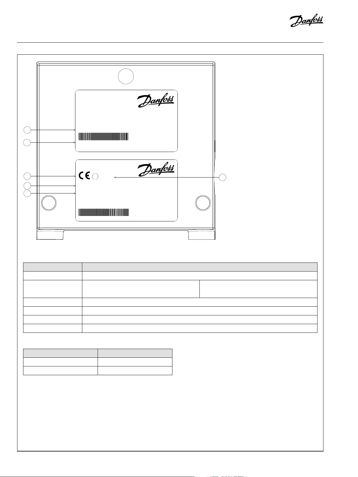
Nameplate key
Nameplate legend
Number Description
1 PVG Valve Group code number
2
3 CE Conformity marking
4 EU marking (per 80079) - Standard part
5 Ambient temperature range
6 EU marking (per 2014/34/EU) - Directive part
Code number, production date,
and serial number
Example: 42 12 C xxxxxx
Week: 42, Year: 2012,
Day: C=Wednesday (A=Monday), Serial number
T-category with ambient temperature at 65°C [149°F]
Oil inlet temperature T-category
≤ 79°C [174°F] T5
79 - 90°C [174 - 194°F] T4
2 | © Danfoss | June 2019 AN290860296423en-000103
Page 3
Installation Guide
Proportional Valve Group PVG-EX
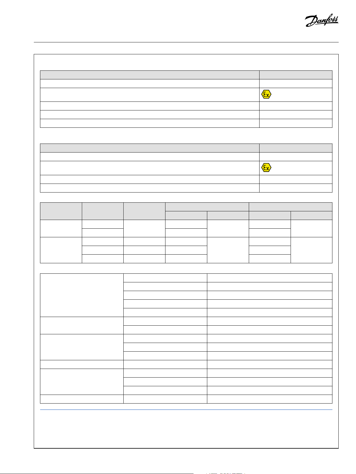
Ex marking (EN 80079-36 standard part)
Description EU Marking
Protection principle h
Explosion protection marking
Equipment group I / II
Equipment protection level (EPL) Mb / Gb
T-class T5...T4
Ex marking (EU Directive part)
Description EU Marking
CE conformity marking CE
Explosion protection marking
Equipment Group I / II
Equipment Category M2 / 2G
EPL/Equipment category
Definition Level of
protection
Mines Very high N/A Ma I M1 I
High Mb M2
Gas atmosphere Very high 0 Ga II 1G II
High 1 Gb 2G
Enhanced 2 Gc 3G
Typical zone of
application
IEC EU
EPL Group Category Group
Technical data
Maximum rated pressure P-port continuous 350 bar [5075 psi]
P-port intermittent 400 bar [5800 psi]
T-port static/dynamic 25/40 bar [365/580 psi
A/B-port continuous 350 bar [5075 psi]
A/B-port intermittent 420 bar [5800 psi]
Maximum rated flow P-port 140 l/min [37 US gal/min]
Port A/B 125 l/min [33 US gal/min]
Oil temperature Recommended 30 to 60°C [86 to 140°F]
Minimum -30°C [-22°F]
Maximum 90°C [194°F]
Ambient temperature Recommended -30 to 60°C [-22 to 140°F]
Oil viscosity Operating range 12 to 75 cSt [65 to 347 SUS]
Minimum 4 cSt [39 SUS]
Maximum 460 cSt [2128 SUS]
Oil cleanliness Minimum 23/19/16 (according to ISO 4406)
Standard hydraulic oil has a flash point (COC) ignition temperature of 230ºC [446ºF] and auto ignition temperature 343ºC [649ºF].
Hydraulic fluid used must fulfill requirements for Auto Ignition temperature for the designated area.
Recommended:
©
Danfoss | June 2019 AN290860296423en-000103 | 3
Page 4
PVP
PVB
PVBZ
PVS
PVLP/PVLA
D
xxxxxxxx
xxxxxxxxxx
PVM
PVE-Ex
PVH
PVMD
C
xxxxxxxx
xxxxxxxxxx
xxxxxxxx
xxxxxxxxxx
B
Installation Guide
Proportional Valve Group PVG-EX
ISO VG 68
ISO VG 46
ISO VG 32
•
DIN 51524-2: Mineral oil hydraulic fluids of category HLP
•
DIN 51524-3: Mineral oil hydraulic fluids of category HVLP
•
ISO 11158: Mineral oil hydraulic fluids of category HM
•
ISO 11158: Mineral oil hydraulic fluids of category HV
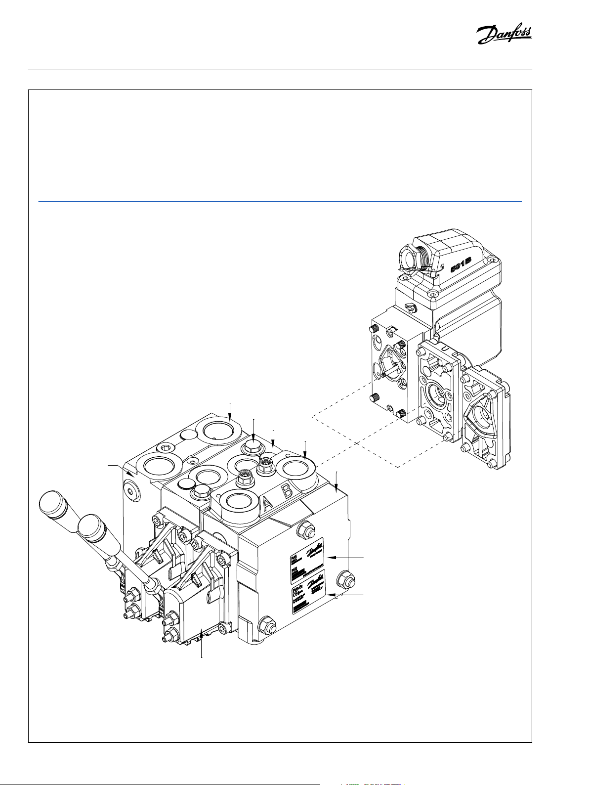
Identification
B PVG-EX label
C PVG number, week and year of installation, series number and PVP-pressure setting
D Engraved part number on PVP and PVB
4 | © Danfoss | June 2019 AN290860296423en-000103
Page 5
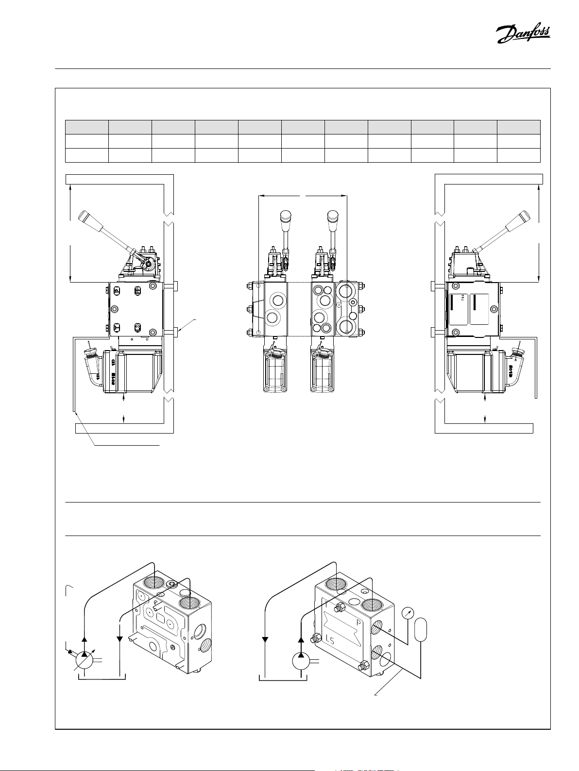
*170[6.7]
*170[6.7]
L
*85[3.3]
*85[3.3]
In particularly exposed applications, protection in the form of
screening of the electrical actuator is recommended
PVP/PVSI:
Max. 40 Nm
[354 lbf · in]
PVS:
Max. 20 Nm
[177 lbf · in]
PVG-Ex
Ex h db I Mb T5...T4
Ta -40° to +60°C
111328133613A147305-EX
Ԑx
I M2
MADE IN DENMARK
Nordborgvej 81
6430 Nordborg, DK
PVG
XXXXXXXXXXXXXXXXXXX
RATED P:
MADE IN DENMARK
Nordborgvej 81, 6430 Nordborg, DK
SEE INSTRUCTION
PVG
XXXXXXXX
W
Accumulator port
Installation Guide
Proportional Valve Group PVG-EX
Installation and plug orientation
PVB 1 2 3 4 5 6 7 8 9 10
L (mm) 82 130 178 226 274 322 370 418 466 514
L (in) 3.23 5.12 7.01 8.90 10.79 12.68 14.57 16.46 18.35 20.24
* Room for dismantling
Warning
It is important to keep the moving parts of the PVG clean and free of dust at all times. PVM lever with plastic knob must have
sufficient space for free movement.
Connection - PVP, pump side module
©
Danfoss | June 2019 AN290860296423en-000103 | 5
Page 6

LS
B
AB
LS
A
Installation Guide
Proportional Valve Group PVG-EX
PVB, basic module
Connection threads type G (ISO 228-1)
Max. tightening torques
Connection P A/B T LS,M, LSA, LSB,
PVH, Accu
Sealing \
G 1/2 G 3/4 G 1/2 G 3/4 G 1/4 G 1/8 G 1/4
Thread
With steel
washer
With copper
washer
With aluminum
washer
With cutting
edge
130 N•m
[1150 lbf•in]
30 N•m
[270 lbf•in]
70 N•m
[620 lbf•in]
130 N•m
[1150 lbf•in]
210 N•m
[1850 lbf•in]
50 N•m
[445 lbf•in]
110 N•m
[970 lbf•in]
210 N•m
[1850 lbf•in]
130 N•m
[1150 lbf•in]
30 N•m
[270 lbf•in]
70 N•m
[620 lbf•in]
130 N•m
[1150 lbf•in]
210 N•m
[1850 lbf•in]
50 N•m
[445 lbf•in]
110 N•m
[970 lbf•in]
210 N•m
[1850 lbf•in]
40 N•m
[350 lbf•in]
20 N•m
[180 lbf•in]
30 N•m
[270 lbf•in]
40 N•m
[350 lbf•in]
UN and UNF connection threads - O-ring boss port
Max. tightening torques
Connection P A/B T LS, M, LSA, LSB,
PVH, Accu
Screwed
connection \
UNF
O-ring
7/8 in - 14 1 1/16 in - 12 7/8 in - 14 1 1/16 in - 12 1/2 in - 20 3/8 in - 24 1/2 in - 20
90 N•m
[800 lbf•in]
120 N•m
[1060 lbf•in]
90 N•m
[800 lbf•in]
120 N•m
[1060 lbf•in]
30 N•m
[270 lbf•in]
LX, PVS, PVSI
17 N•m
[150 lbf•in]
15 N•m
[135 lbf•in]
15 N•m
[135 lbf•in]
17 N•m
[150 lbf•in]
LX, PVS, PVSI
10 N•m
[90 lbf•in]
40 N•m
[350 lbf•in]
20 N•m
[180 lbf•in]
30 N•m
[270 lbf•in]
40 N•m
[350 lbf•in]
30 N•m
[270 lbf•in]
6 | © Danfoss | June 2019 AN290860296423en-000103
Page 7

Q max: P → B
Q max: P → A
PVS
PVB
PVP
PVE-EX
V310474.A
PVM
7-9 N•m
[61-79 lbf•in]
P → A
B
A
Q max: P → B
Q max: P → A
PVS
PVB
PVP
PVE-EX
V310465.A
PVM
7-9 N•m
[61-79 lbf•in]
P → A
B
A
Installation Guide
Proportional Valve Group PVG-EX
Mounting of PVE
Standard assembly
Optional assembly
©
Danfoss | June 2019 AN290860296423en-000103 | 7
Page 8

*170[6.7]
*85[3.3]
C
LS
B
C
C
LS
A
C
CLSC
Installation Guide
Proportional Valve Group PVG-EX
PVG - Bleeding
If the group is installed vertically, it is recommended to bleed it at the adjusting screws.
Because of the hydraulic build-up of PVEA, it may be necessary to bleed it.
PVG - Pressure setting - PVP, LSA, LS
B
8 | © Danfoss | June 2019 AN290860296423en-000103
Page 9

8 ±1 N•m
3 (1±0.15N•m)
19
.5
°
19
.
5°
W
5 [0.2]
8 ± 0.5 Nm
[70 ± 4.4 lbf in]
Installation Guide
Proportional Valve Group PVG-EX
PVM - Installation of lever
Screw the lever completely home
Warning
PVG must only be used with the Danfoss certified manual lever with plastic knob. Lever must have sufficient space for free
movement to prevent impact with solid objects that are not part of the PVG.
PVE - Installation
PVE-EX Standard
For installation, mounting, and technical data of the PVE-EX, please see PVE-EX Installation Guides document number:
•
•
•
AN00000349 for eb mb version
AN00000351 for db version
AN00000365 for UL version
©
Danfoss | June 2019 AN290860296423en-000103 | 9
Page 10

Installation Guide
Proportional Valve Group PVG-EX
EU declaration of conformity, page 1
10 | © Danfoss | June 2019 AN290860296423en-000103
Page 11

Installation Guide
Proportional Valve Group PVG-EX
EU declaration of conformity, page 2
©
Danfoss | June 2019 AN290860296423en-000103 | 11
Page 12

Installation Guide
Proportional Valve Group PVG-EX
EU declaration of conformity, page 3
12 | © Danfoss | June 2019 AN290860296423en-000103
Page 13

Installation Guide
Proportional Valve Group PVG-EX
EU declaration of conformity, page 4
©
Danfoss | June 2019 AN290860296423en-000103 | 13
Page 14

EU declaration of conformity, page 5
Danfoss can accept no responsibility for possible errors in catalogues, brochures and other printed material. Danfoss reserves the right to alter its products without notice. This also applies to products
already on order provided that such alterations can be made without subsequent changes being necessary in specifications already agreed.
All trademarks in this material are property of the respective companies. Danfoss and the Danfoss logotype are trademarks of Danfoss A/S. All rights reserved.
14 | © Danfoss | June 2019 AN290860296423en-000103
 Loading...