

Technical Information
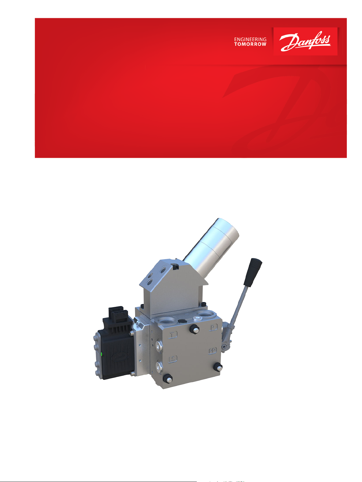
Proportional Valve Group
PVG 32 miniBOOSTER
www.danfoss.com
Technical Information
PVG 32 Proportional Valve Group miniBOOSTER
Revision history Table of revisions
Date Changed Rev
November 2018 Updated schematics 0301
February 2018 Add new modules 0201
August 2015 Drawing updated 00.04
February 2014 Converted to Danfoss layout – DITA CMS AD
Oct 2010 - June 2013 Various changes AB-AC
June 2002 New Edition AA
2 | © Danfoss | November 2018 520L0543 | BC00000103en-000301

Technical Information
PVG 32 Proportional Valve Group miniBOOSTER
Contents
General Information
PVG 32 miniBOOSTER..................................................................................................................................................................... 4
HC3-PVG32 miniBOOSTER
Technical data....................................................................................................................................................................................5
Flow rates and intensification factor.........................................................................................................................................5
Function...............................................................................................................................................................................................6
Ordering...............................................................................................................................................................................................7
M-HC-010
Technical data....................................................................................................................................................................................8
Intensification factors......................................................................................................................................................................8
Function............................................................................................................................................................................................ 10
Ordering............................................................................................................................................................................................ 10
M-HC-011
Technical data................................................................................................................................................................................. 11
Intensification factors...................................................................................................................................................................12
Function............................................................................................................................................................................................ 13
Ordering............................................................................................................................................................................................ 13
©
Danfoss | November 2018 520L0543 | BC00000103en-000301 | 3

Technical Information
PVG 32 Proportional Valve Group miniBOOSTER
General Information
PVG 32 miniBOOSTER
The PVG miniBOOSTER raises the hydraulic pressure from the pump to the workload. It is ideal when you
need an extra high outlet pressure, either constantly or temporarily.
The PVG miniBOOSTER is typically used in mobile attachments, cranes, off highway equipment, injection
molding machines and hydraulic presses. It is applicable to machines with insufficient pump capacity to
prevent machine stoppage when peak pressures occur.
The PVG miniBOOSTER comes in the following three main variants:
HC3-PVG
•
M-HC-010
•
M-HC-011
•
All ordering, inquiries, technical support etc. of the miniBOOSTER products must be directed to
miniBOOSTER Hydraulics A/S. For further information and contact details please visit the miniBOOSTER
website. https://www.minibooster.com
4 | © Danfoss | November 2018 520L0543 | BC00000103en-000301
Ă
50
G1/4"
110
28,6
178,2
5
156
64
8
44
72,5
46
37,5
39,3
16,5
35,5
105
17,5
Technical Information
PVG 32 Proportional Valve Group miniBOOSTER
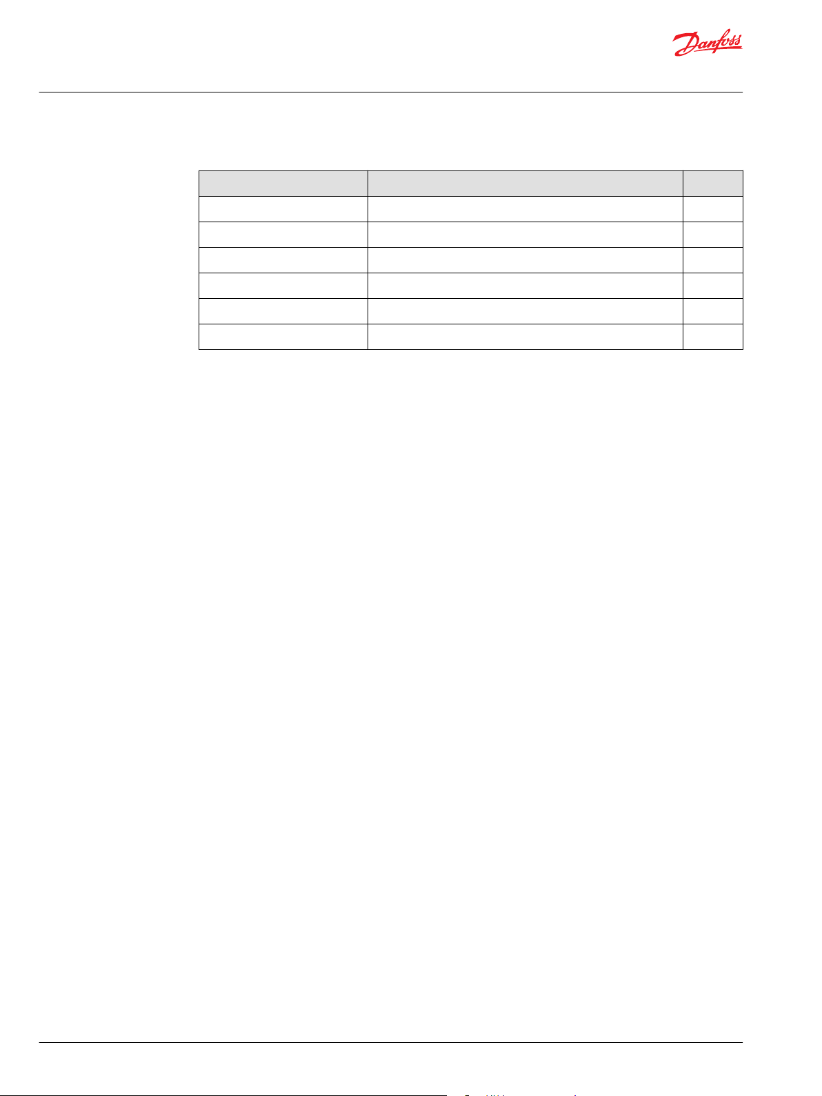
HC3-PVG32 miniBOOSTER
The HC3-PVG32 is a compact unit weighing only 4.0 kg. It is ideal for use in a variety of applications where
building up and maintaining high pressure is required. The HC3-PVG32 raises supplied pressure to a
higher outlet pressure and automatically compensates for consumption of oil to maintain the high
pressure. Adjustment of the outlet pressure is carried out by varying the supplied pressure.
Dimensions in mm
Technical data
Flow rates and intensification factor
©
Danfoss | November 2018 520L0543 | BC00000103en-000301 | 5
Operating parameters
Inlet pressure range
Maximum outlet pressure
Intensification factor; i Average outlet flow l/min [US gal/
min]
1.2 1.2 [0.264] 8.0 [1.76]
1.5 1.0 [0.220] 8.0 [1.76]
2.0 0.8 [176] 8.0 [1.76]
2.8 0.6 [132] 8.0 [1.76]
3.2 2.5 [0.550] 15.0 [3.30]
4.0 2.0 [0.440] 14.0 [3.08]
5.0 1.6 [0.352] 14.0 [3.08]
20 – 200 bar [290 - 2900 psi]
800 bar [11 603 psi]
Maximum inlet flow l/min [US gal/
min]

Technical Information
PVG 32 Proportional Valve Group miniBOOSTER
HC3-PVG32 miniBOOSTER
6.6 1.3 [0.286] 13.0 [2.86]
9.0 0.9 [198] 13.0 [2.86]
13.0 0.6 [132] 12.0 [2.64]
20.0 0.3 [066] 12.0 [2.64]
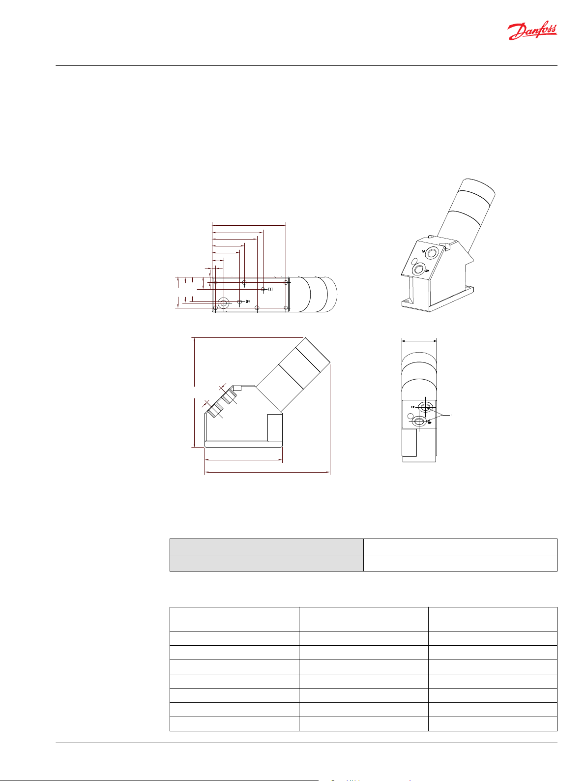
Function
The basic operation is illustrated in the function diagram. Oil is fed through the proportional valve PVG32
to the IN port in the HC3-PVG, flowing freely through the check valves KV1, KV2 and DV to the high
pressure side HP. In this condition maximum flow through the booster is achieved giving a fast forward
function.
When pump pressure is reached on the high pressure side HP, valves KV1, KV2 and DV will close. The end
pressure will be achieved by the oscillating pump unit OP. The unit will automatically stall when end
pressure on high pressure side HP is reached. If there is a pressure drop on the high pressure side due to
consumption or leakage, the OP valve will automatically operate to maintain the end pressure. Pressure
can be relieved from the high pressure side HP through the pilot operated check valve DV. By connecting
port R to the supply pressure and port IN to tank, allowing the fluid from the high pressure side HP to
flow back to tank.
6 | © Danfoss | November 2018 520L0543 | BC00000103en-000301

A
157B6849
B
R
IN
KV2
KV1
DV
R
IN
A
B
OP
A
HP
LP
HC3-PVG32
Low pressure
High pressure
157B7000
LS
T
P
M
Technical Information
PVG 32 Proportional Valve Group miniBOOSTER
HC3-PVG32 miniBOOSTER
Schematic
Ordering
The following part numbers are for the parts you have to order through Danfoss Power Solutions. To do
so, please contact your Danfoss Power Solutions sales representative.
Part Number Type
157B6849 PVG 32: PVB basic module
157B7000 Spool flow 10 l/min [2.6 US gal/min]
©
Danfoss | November 2018 520L0543 | BC00000103en-000301 | 7
www.minibooster.com/products/boosters-oil/hc3-pvg32.html )
For further details on the miniBOOSTER HC3-PVG and to order it, click here (link to https://

5,3
179,9
116,7
110
55
48,5
43,6
31,5
19
105
72,5
64
46
16
37,5
16,5
36
72
60
90
173,6
5
Technical Information
PVG 32 Proportional Valve Group miniBOOSTER
M-HC-010
The M-HC-010 In-line Intensifier System is designed to boost the hydraulic pressure from the pump to the
workload. The system operates by solenoid activation. The operator is in full control of the system and
can decide if a boosted pressure to the workload should be applied.
The system is dynamical by means of being able to provide flow at high pressure for intermittent use (<
10 min duty cycle).
A relief valve is installed to control the maximum allowable pressure that the system can output, and
allowing the booster to go for a higher end pressure producing flow at the decided pressure.
Dimensions in mm
Technical data
Operating parameters
Inlet pressure range 20-207 bar [290-3000 psi]
Maximum outlet pressure 700 bar [11603 psi]
Bypass flow 100 l/min [26 US gal/min]
Intensification factors
8 | © Danfoss | November 2018 520L0543 | BC00000103en-000301
HC2D HC3
1.6 1.5
1.9 2.0
2.2 2.8

Technical Information
PVG 32 Proportional Valve Group miniBOOSTER
M-HC-010
2.6 3.2
3.2 4.0
4.0 5.0
5.0 6.6
6.6 9.0
9.0 -
The intensification factor depends on available inlet and desired outlet pressure. To calculate the initial
factor, use the following formula:
i = Desired high pressure / pump pressure
Desired pressure: 500 bar
Pump pressure: 200 bar
i = 500 / 200 = 2.5
For static use: Select an intensification factor higher or equal to the calculated value. In this case i = 2.8
with HC3 booster. The desired pressure of 500 bar is finally adjusted with the HP relief valve.
For dynamic use: Select an intensification factor 60% higher than the calculated value. In this case i =
500 / 200 = 2.5 + 60% = 4.0 The desired pressure of 500 bar is finally adjusted with the HP relief valve.
©
Danfoss | November 2018 520L0543 | BC00000103en-000301 | 9
A
M-HC-010
B
LS
T
P
M
157B7000
H
P
T
1
3
1: Directional Valve
3: Relief Valve
2: Pilot Operated Check Valve
4: Check Valve
2
Z
4
4
Port details:
P: Flow from pump.
A or B port on directional valve.
T: Flow to tank.
A or B port on directional valve.
H: High pressure port to cylinder.
Z: Low pressure port to cylinder.
M
IN
R
H
Technical Information
PVG 32 Proportional Valve Group miniBOOSTER
M-HC-010
Function
Schematic
Ordering
The following part numbers are for the parts you have to order through Danfoss Power Solutions. To do
so, please contact your Danfoss Power Solutions sales representative.
Part Number Type Flow l/min [US gal/min]
157B6849 PVG 32: PVB basic module
157B7005 Spool 5 [1.3]
157B7000 Spool 10 [2.6]
157B7001 Spool 25 [6.6]
157B7002 Spool 40 [10.6]
157B7003 Spool 65 [1732]
157B7004 Spool 100 [26.4]
For further details on the miniBOOSTER M-HC-010 PVG and to order it, click here (link to https://
www.minibooster.com/products/intensifier-systems-2/m-hc-010.html )
10 | © Danfoss | November 2018 520L0543 | BC00000103en-000301

5,3
116,7
110
72
36
16
105
37,5
72,5
19
46
64
5
48,5
16,5
55
31,5
43,6
205,6
90
60
242,6
Technical Information
PVG 32 Proportional Valve Group miniBOOSTER
M-HC-011
The M-HC-011 In-line Intensifier System is designed to boost the hydraulic pressure from the pump to the
workload. It operates only when needed, to save energy.
The system is dynamical by means of being able to provide flow at high pressure for intermittent use (<
10 min duty cycle).
The hydraulic oil is by-passed directly from the pump to the workload at maximum flow when back
pressure from the workload has reached a set point close to the maximum pressure of pump.
A sequence valve opens and directs the oil to the booster, which makes the pressure rise. The shift
between maximum pump pressure and high pressure happens without intervention from the user and
ensures that the workload at all times will be driven at a maximum speed in relation to the required high
pressure.
A relief valve is installed to control the maximum allowable pressure that the system can output, and
allowing the booster to go for a higher end pressure producing flow at the decided pressure.
Dimensions in mm
This is the dimensional drawings for the M-HC2D-011-FL100-PVG32. For the dimensional drawings for the
M-HC3-011-FL100-PVG32, click here (https://www.minibooster.com/fileadmin/user_upload/PDF/m-
hc_-011/M-HC3-011-FL100-PVG32-00._Assembly_drawing_01.pdf )
Technical data
Operating parameters
©
Danfoss | November 2018 520L0543 | BC00000103en-000301 | 11
Inlet pressure range 20-207 bar [290-3000 psi]
Maximum outlet pressure 700 bar [11603 psi]
Bypass flow 100 l/min [26 US gal/min]

Technical Information
PVG 32 Proportional Valve Group miniBOOSTER
M-HC-011
Intensification factors
HC2D HC3
1.6 1.5
1.9 2.0
2.2 2.8
2.6 3.2
3.2 4.0
4.0 5.0
5.0 6.6
6.6 9.0
9.0 -
The intensification factor depends on available inlet and desired outlet pressure. To calculate the initial
factor, use the following formula:
i = Desired high pressure / pump pressure
Desired pressure: 500 bar
Pump pressure: 200 bar
i = 500 / 200 = 2.5
For static use: Select an intensification factor higher or equal to the calculated value. In this case i = 2.8
with HC3 booster. The desired pressure of 500 bar is finally adjusted with the HP relief valve.
For dynamic use: Select an intensification factor 60% higher than the calculated value. In this case i =
500 / 200 = 2.5 + 60% = 4.0 The desired pressure of 500 bar is finally adjusted with the HP relief valve.
12 | © Danfoss | November 2018 520L0543 | BC00000103en-000301

A
M-HC-011
B
LS
T
P
M
157B7000
1: Sequence Valve
3: Relief Valve
2: Pilot Operated Check Valve
4: Check Valve
Port details:
P: Flow from pump.
A or B port on directional valve.
T: Flow to tank.
A or B port on directional valve.
H: High pressure port to cylinder.
Z: Low pressure port to cylinder.
IN
R
H
H
P
T
1
3
2
Z
4
4
M
Technical Information
PVG 32 Proportional Valve Group miniBOOSTER
M-HC-011
Function
Schematic
Ordering
The following part numbers are for the parts you have to order through Danfoss Power Solutions. To do
so, please contact your Danfoss Power Solutions sales representative.
Part Number Type Flow l/min [US gal/min]
157B6849 PVG 32: PVB basic module
157B7005 Spool 5 [1.3]
157B7000 Spool 10 [2.6]
157B7001 Spool 25 [6.6]
157B7002 Spool 40 [10.6]
157B7003 Spool 65 [1732]
157B7004 Spool 100 [26.4]
For further details on the miniBOOSTER M-HC-011 PVG and to order it, click here (link to https://
www.minibooster.com/products/intensifier-systems-2/m-hc-011.html )
©
Danfoss | November 2018 520L0543 | BC00000103en-000301 | 13

Technical Information
PVG 32 Proportional Valve Group miniBOOSTER
14 | © Danfoss | November 2018 520L0543 | BC00000103en-000301

Technical Information
PVG 32 Proportional Valve Group miniBOOSTER
©
Danfoss | November 2018 520L0543 | BC00000103en-000301 | 15

Danfoss
Power Solutions GmbH & Co. OHG
Krokamp 35
D-24539 Neumünster, Germany
Phone: +49 4321 871 0
Danfoss
Power Solutions ApS
Nordborgvej 81
DK-6430 Nordborg, Denmark
Phone: +45 7488 2222
Danfoss
Power Solutions (US) Company
2800 East 13th Street
Ames, IA 50010, USA
Phone: +1 515 239 6000
Danfoss
Power Solutions Trading
(Shanghai) Co., Ltd.
Building #22, No. 1000 Jin Hai Rd
Jin Qiao, Pudong New District
Shanghai, China 201206
Phone: +86 21 3418 5200
Products we offer:
Comatrol
www.comatrol.com
Turolla
www.turollaocg.com
Hydro-Gear
www.hydro-gear.com
Daikin-Sauer-Danfoss
www.daikin-sauer-danfoss.com
DCV directional control
•
valves
Electric converters
•
Electric machines
•
Electric motors
•
Hydrostatic motors
•
Hydrostatic pumps
•
Orbital motors
•
PLUS+1® controllers
•
PLUS+1® displays
•
PLUS+1® joysticks and
•
pedals
PLUS+1® operator
•
interfaces
PLUS+1® sensors
•
PLUS+1® software
•
PLUS+1® software services,
•
support and training
Position controls and
•
sensors
PVG proportional valves
•
Steering components and
•
systems
Telematics
•
Danfoss Power Solutions is a global manufacturer and supplier of high-quality hydraulic and
electric components. We specialize in providing state-of-the-art technology and solutions
that excel in the harsh operating conditions of the mobile off-highway market as well as the
marine sector. Building on our extensive applications expertise, we work closely with you to
ensure exceptional performance for a broad range of applications. We help you and other
customers around the world speed up system development, reduce costs and bring vehicles
and vessels to market faster.
Danfoss Power Solutions – your strongest partner in mobile hydraulics and mobile
electrification.
Go to www.danfoss.com for further product information.
We offer you expert worldwide support for ensuring the best possible solutions for
outstanding performance. And with an extensive network of Global Service Partners, we also
provide you with comprehensive global service for all of our components.
Local address:
Danfoss can accept no responsibility for possible errors in catalogues, brochures and other printed material. Danfoss reserves the right to alter its products without notice. This also applies to products
already on order provided that such alterations can be made without subsequent changes being necessary in specifications already agreed.
All trademarks in this material are property of the respective companies. Danfoss and the Danfoss logotype are trademarks of Danfoss A/S. All rights reserved.
©
Danfoss | November 2018 520L0543 | BC00000103en-000301
 Loading...