

Page 1
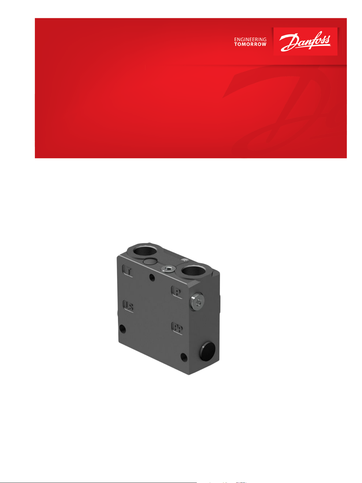
Application Guide
PVG 32
Improve stability in open center systems
by reducing pressure spikes
powersolutions.danfoss.com
Page 2

Application Guide
Improve stability in open center systems by reducing pressure spikes
Revision history Table of revisions
Date Changed Rev
Feb 2017 First edition 0101
2 | © Danfoss | Feb 2017 AB00000078en-US0101
Page 3
W
C
Application Guide
Improve stability in open center systems by reducing pressure spikes
About this document
References
Related literature: PVG 32 Proportional Valve Group Technical Information, 520L0344, BC00000038
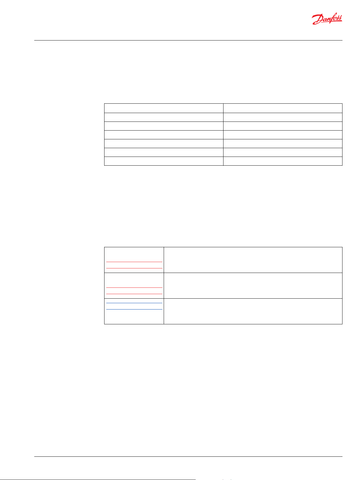
Terms and definitions
Term Definition
OC Open Center
Important user information
P
LS
PVE Proportional Valve Electrohydraulic actuator
PVG Proportional Valve Group
PVP Proportional Valve Pump side module
T0 Low Pressure Tank Line
Danfoss is not responsible or liable for indirect or consequential damages resulting from the use or
application of this equipment.
The examples and diagrams in this manual are included for illustration purposes. Due to the many
variables and requirements associated with any particular installation, Danfoss cannot assume
responsibility or liability for the actual used bases on the examples and diagrams.
Reproduction of whole or part of the contents of this manual is prohibited.
The following notes are used to raise awareness of safety considerations.
Load Sense Pressure
Xxxxx
Xxxx
Note
Warning
Caution
Identifies information about practices or circumstances that can cause a hazardous
situation, which may lead to personal injury or death, damage or economic loss.
Identifies information about practices or circumstances that can lead to personal injury
or death, property damage, or economic loss. Attentions help you identify a hazard,
avoid a hazard, and recognize the consequence
Identifies information that is critical for successful application and understanding of the
product.
Identifies a typical use of a functionality or parameter value. Use recommendations as a
starting point for the final configuration process of the system.
©
Danfoss | Feb 2017 AB00000078en-US0101 | 3
Page 4

Application Guide
Improve stability in open center systems by reducing pressure spikes
Application overview
When using a small orifice in the load sense line within an open center (OC) system, there will be rapid
changes from high pressure to low pressure in the load sense signal due to the quick return of the main
spool to its neutral position.
In this document you can read about the difference of using a small orifice in the load sense line and
using a combined orifice and check valve. The purpose is to show why and how using the combined
orifice and check valve can lead to reduced pressure peaks and thereby improved stability.
4 | © Danfoss | Feb 2017 AB00000078en-US0101
Page 5

Application Guide
Improve stability in open center systems by reducing pressure spikes
Explanation of the rapid pressure drop
When you are using a PVG valve together with a fixed displacement pump, the pump module is
configured to run in an open center mode. This means that the pressure adjustment spool leads the flow
across to a tank connection that determines the pump stand-by pressure when no work sections are
actuated. When pressure is needed at a work section to perform a task, this tank connection is partially or
fully closed by the internal load sense network.
The force of the neutral adjustment spring causes the main spool of a working section to quickly return to
its neutral position. This causes the load sense signal to rapidly switch from high pressure to low pressure.
When the load sense signal changes the pressure adjustment spool in the PVG inlet module, the spool
must return to neutral and the tank connection will then reopen and relieve the pressure. The fast
change in the load sense signal will create a pressure peak. This peak is especially undesirable when using
a PVE in a valve stack that is not configured with T0.
These pressure peaks in the tank line can be reduced by replacing the small orifice in the load sense line
from the work sections with a combined orifice and check valve as seen in the following figure.
Combined orifice and check valve
Comparison of modules on page 6 shows a module with small orifice and a module with combined
orifice and check valve.
©
Danfoss | Feb 2017 AB00000078en-US0101 | 5
Page 6

Application Guide
Improve stability in open center systems by reducing pressure spikes
Explanation of the rapid pressure drop
Comparison of modules
Left schematic Default OC PVP with orifice
Right schematic Special OC PVP with combined orifice and check valve
6 | © Danfoss | Feb 2017 AB00000078en-US0101
Page 7

Application Guide
Improve stability in open center systems by reducing pressure spikes
Pressure drop comparison
In a module with a small orifice, the load sense signal will be relieved to tank in approximately 150 ms
through the Ø1-mm orifice when the work sections are moved to neutral position.
In a module with a combined orifice and check valve, the load sense signal will be relieved to tank in
approximately 350 ms through the combined check valve and Ø1-mm orifice.
See the following comparison of the pressure drop in the two different modules.
Pressure drop comparison
A Pressure (bar)
B Time (seconds)
C PLS orifice only
D PLS orifice and check valve
When the time to relieve the load sense signal to tank is increased, there will also be an increased
possibility that pressure peaks will be created in the pump line.
This scenario is especially important to consider if the valve uses full pump flow, and if the valve is not
ramped back to neutral but shifts suddenly due to the force of the neutral adjustment spring in the main
spool.
In addition, you should consider whether the connection leaves enough flexibility to absorb the pressure
peaks. For example, there might not be enough flexibility if you use a rigid connection between the
pump and P-port of the pump module, or if you place the valve stack close to the pump with a very small
connection of any sort. As a result, the pressure peaks will be transferred to the pump and possibly
increase wear.
Our recommendation is to use a relatively long hose connection between the pump and the P-port of the
pump module. The flexibility of this hose connection will absorb the pressure peaks.
©
Danfoss | Feb 2017 AB00000078en-US0101 | 7
Page 8

Application Guide
Improve stability in open center systems by reducing pressure spikes
Summary
Using an open center inlet module with a combined orifice and check valve will increase the time it takes
to relieve the load sense pressure in the tank line. This will lead to reduced pressure peaks in the tank line.
However, this will also increase the possibility of pressure peaks in the pump line. But with a relatively
long hose connection between the pump and the P-port of the pump module, these pressure peaks will
be absorbed. Combining an open center inlet module with a combined orifice and check valve together
with a relatively long hose connection has been used to increase stability with great results.
For test purposes, you can acquire a combined check valve and orifice by ordering part number
155L5230.
8 | © Danfoss | Feb 2017 AB00000078en-US0101
Page 9

Danfoss
Power Solutions GmbH & Co. OHG
Krokamp 35
D-24539 Neumünster, Germany
Phone: +49 4321 871 0
Danfoss
Power Solutions ApS
Nordborgvej 81
DK-6430 Nordborg, Denmark
Phone: +45 7488 2222
Danfoss
Power Solutions (US) Company
2800 East 13th Street
Ames, IA 50010, USA
Phone: +1 515 239 6000
Danfoss
Power Solutions Trading
(Shanghai) Co., Ltd.
Building #22, No. 1000 Jin Hai Rd
Jin Qiao, Pudong New District
Shanghai, China 201206
Phone: +86 21 3418 5200
Products we offer:
Comatrol
www.comatrol.com
Turolla
www.turollaocg.com
Hydro-Gear
www.hydro-gear.com
Daikin-Sauer-Danfoss
www.daikin-sauer-danfoss.com
Bent Axis Motors
•
Closed Circuit Axial Piston
•
Pumps and Motors
Displays
•
Electrohydraulic Power
•
Steering
Electrohydraulics
•
Hydraulic Power Steering
•
Integrated Systems
•
Joysticks and Control
•
Handles
Microcontrollers and
•
Software
Open Circuit Axial Piston
•
Pumps
Orbital Motors
•
PLUS+1® GUIDE
•
Proportional Valves
•
Sensors
•
Steering
•
Transit Mixer Drives
•
Danfoss Power Solutions is a global manufacturer and supplier of high-quality hydraulic and
electronic components. We specialize in providing state-of-the-art technology and solutions
that excel in the harsh operating conditions of the mobile off-highway market. Building on
our extensive applications expertise, we work closely with our customers to ensure
exceptional performance for a broad range of off-highway vehicles.
We help OEMs around the world speed up system development, reduce costs and bring
vehicles to market faster.
Danfoss – Your Strongest Partner in Mobile Hydraulics.
Go to www.powersolutions.danfoss.com for further product information.
Wherever off-highway vehicles are at work, so is Danfoss. We offer expert worldwide support
for our customers, ensuring the best possible solutions for outstanding performance. And
with an extensive network of Global Service Partners, we also provide comprehensive global
service for all of our components.
Please contact the Danfoss Power Solution representative nearest you.
Local address:
Danfoss can accept no responsibility for possible errors in catalogues, brochures and other printed material. Danfoss reserves the right to alter its products without notice. This also applies to products
already on order provided that such alterations can be made without changes being necessary in specifications already agreed.
All trademarks in this material are property of the respective companies. Danfoss and the Danfoss logotype are trademarks of Danfoss A/S. All rights reserved.
©
Danfoss | Feb 2017 AB00000078en-US0101
 Loading...