

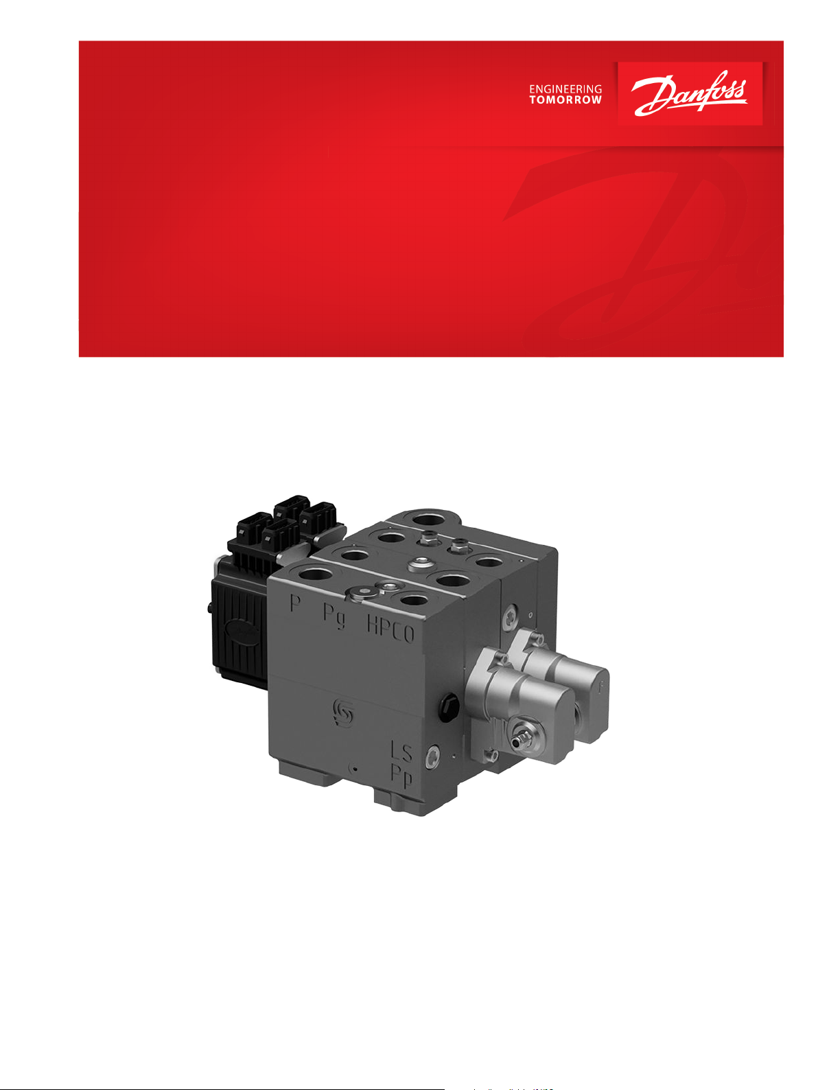
Installation Guide
Proportional Valve Group
PVG 20
www.danfoss.com

Installation Guide
Proportional Valve Group PVG 20
Revision history Table of revisions
Date Changed Rev
February 2021 First edition 0101
2 | © Danfoss | February 2021 AN370056593720en-000101

Installation Guide
Proportional Valve Group PVG 20
Contents
PVG 20 installation guide
Identification......................................................................................................................................................................................4
Installation...........................................................................................................................................................................................5
Connection, pump side module, PVP....................................................................................................................................... 5
Connection, basic module, PVBZ/PVBZ-HS.............................................................................................................................6
Maximum tightening torque........................................................................................................................................................7
Installation of lever...........................................................................................................................................................................8
Pressure setting PVP........................................................................................................................................................................8
Oil flow direction.............................................................................................................................................................................. 9
Electrical connection.................................................................................................................................................................... 10
PVED-CC S7 LED colors.................................................................................................................................................................10
Installation of PVED.......................................................................................................................................................................11
Protection and warning...............................................................................................................................................................11
©
Danfoss | February 2021 AN370056593720en-000101 | 3
Installation Guide
Proportional Valve Group PVG 20
PVG 20 installation guide
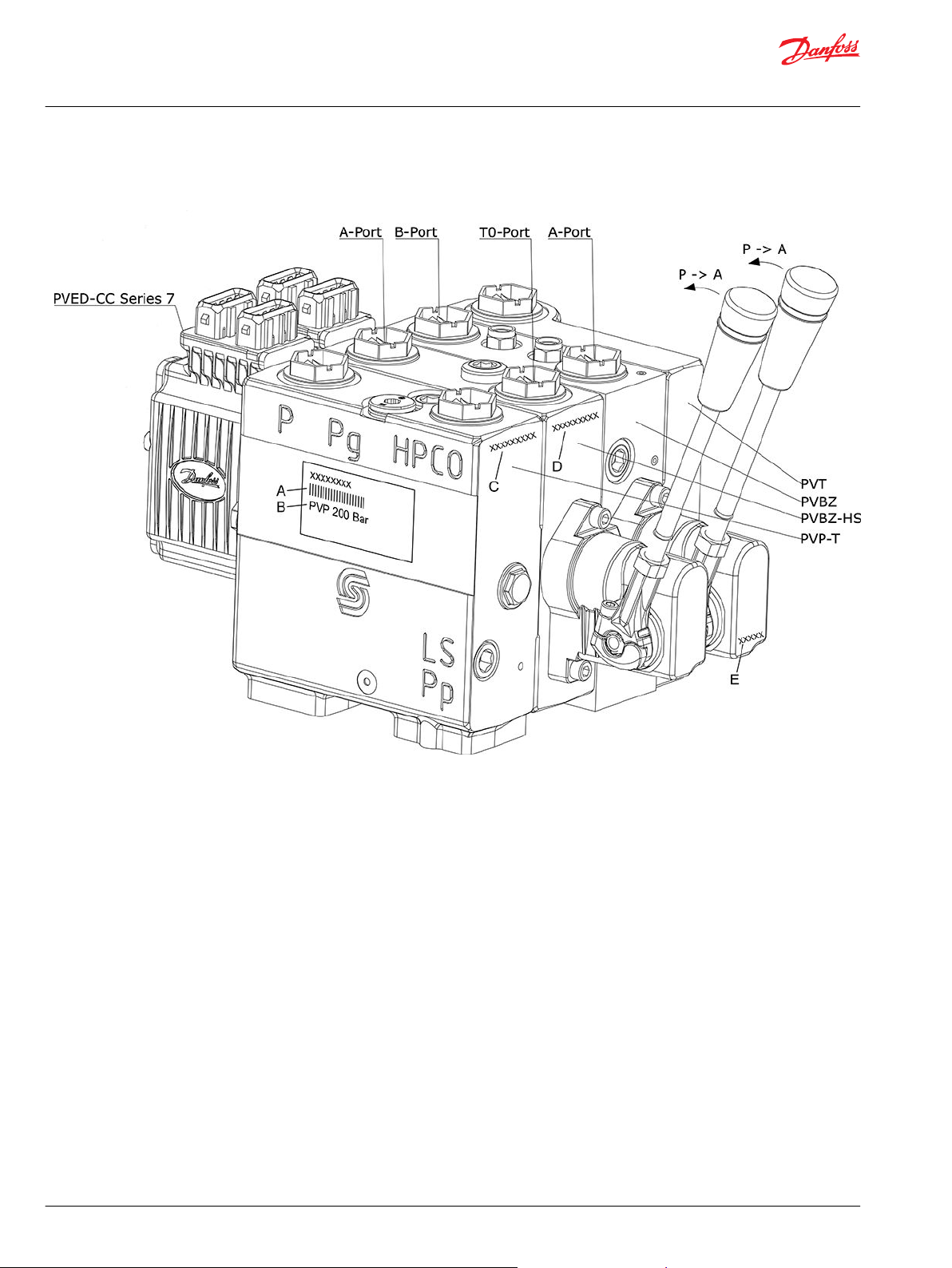
Identification
A PVG-number, week, year and day of assembly, and series number
B PVP - pressure setting
C PVP - number, revision, manufacturing, year, week, day, series number
D PVB - number, revision, manufacturing, year, week, day, series number
E PVM - week and year for manufacturing
4 | © Danfoss | February 2021 AN370056593720en-000101

25Nm
[221 lbf-in]
70[2.756]
100[4]*
215[8.46]
In particularly exposed applications, protection in the form
of screening of the electrical actuator is recommended
L
96[3.78]
4xM8 x min12
[4x5/16-18 UNC min x 0.39]
PVLP
T gauge
Port
LS gauge port
PVPC Cavity
PVLP
T gauge
Port
LS gauge port
PVLP
PVPC Cavity
Installation Guide
Proportional Valve Group PVG 20
PVG 20 installation guide
Installation
*Room for dismantling
PVB 1 2 3 4 5 6 7 8 9 10
L
mm
L
in
Connection, pump side module, PVP
PVP-T
60.5 100.5 140.5 180.5 220.5 260.5 300.5 340.5 380.5 420.5
[2.38] [3.96] [5.53] [7.11] [8.68] [10.26] [11.83] [13.41] [14.98] [16.56]
PVPV
PVP-HPCO
©
Danfoss | February 2021 AN370056593720en-000101 | 5

PVBZ
PVBZ-HS
A-Port
B-Port
T0-Port
A-Port
Installation Guide
Proportional Valve Group PVG 20
PVG 20 installation guide
Connection, basic module, PVBZ/PVBZ-HS
Rated pressure
Product Rated pressure
PVG 20 w. PVBZ 210 bar [3046 psi]
6 | © Danfoss | February 2021 AN370056593720en-000101

Lx
P
ı
Lx on/off selector
CW = Lx on
CCW = Lx off
T gauge port
P pilot gauge port
T gauge port
P gauge port
Ls gauge port
Lx
P
ı
Lx on/off selector
CW = Lx on
CCW = Lx off
T gauge port
Installation Guide
Proportional Valve Group PVG 20
PVG 20 installation guide
Maximum tightening torque
PVT
PVT with gauge port
PVTS
Max. tightening torque Connection Gauge ports
P A/B T, T
0
LS LS, P
PVT PVTS
I
P, Pp
T, LS
Screwed connection Metric M22 x 1.5 M18 x 1.5 M18 x 1.5 M22 x 1.5 M12 x 1.5 M12 x 1.5 M12 x 1.5 M10 x 1.0 M12 x 1.5
With aluminum washer
O-ring
140 N•m
[1240
lbf•in]
60 N•m
[530 lbf•in]
80 N•m
[710 lbf•in]
45 N•m
[400 lbf•in]
80 N•m
[710 lbf•in]
45 N•m
[400 lbf•in]
140 N•m
[1240
lbf•in]
60 N•m
[530 lbf•in]
30 N•m
[265 lbf•in]
25 N•m
[221 lbf•in]
30 N•m
[265 lbf•in]
25 N•m
[221 lbf•in]
30 N•m
[265 lbf•in]
25 N•m
[221 lbf•in]
18 N•m
[160 lbf•in]
15 N•m
[132 lbf•in]
30 N•m
[265 lbf•in]
25 N•m
[221 lbf•in]
©
Danfoss | February 2021 AN370056593720en-000101 | 7

30.7°
16°
15.5°
Float
26.5°
60.7°
120.7°
150.7°
90.7°
V310045.A
V310054.A
Dot visible
15.5°
Float 26.5°
16°
105.7°
75.7°
135.7°
45.7°
15.7°
V310046.A
V310055.A
Dot not visible
Installation Guide
Proportional Valve Group PVG 20
PVG 20 installation guide
Installation of lever
Pressure setting PVP
8 | © Danfoss | February 2021 AN370056593720en-000101

PVED-CC Series 7
A-Port B-Port
A
-
P
ort
T
0-Port
PVT
PVBZ
PVBZ-HS
PVP-T
P
-
> A
P
->
A
Installation Guide
Proportional Valve Group PVG 20
PVG 20 installation guide
Oil flow direction
©
Danfoss | February 2021 AN370056593720en-000101 | 9

Installation Guide
Proportional Valve Group PVG 20
PVG 20 installation guide
Electrical connection
AMP JPT Connector drawing
AMP JPT Connector
Pln. no. Connection / signal
1 Can_L
2 VBAT / U_DC
3 GND
4 Can_H
PVED-CC S7 LED colors
LED Color Indication
Flashing Orange and Green PVED-CC-S7 valve is in bootloader mode
Solid Blue PVED-CC-S7 valve is in bootloader mode and firmware or parameter download is in
progress
Flashing Blue PVED-CC-S7 valve is in bootloader mode and parameter read is in progress if
Solid Orange PVED-CC S7 is in hand operational mode/emergency stop mode
Solid Green PVED-CC S7 is being controlled with non-zero AVC set-point commands.
Flashing Green PVED-CC S7 is in blocked state and spool at neutral position including power save
mode.
Flashing Red PVED-CC S7 is in fault mode (external fault)
Solid Red PVED-CC S7 is in fault mode (internal fault)
10 | © Danfoss | February 2021 AN370056593720en-000101

4[0.16]
5
±0.5 Nm
[44 ± 4.4 lbf in]
W
Installation Guide
Proportional Valve Group PVG 20
PVG 20 installation guide
Installation of PVED
The seal in the PVE connector and the seals for individual conductors are crucial for correctly sealing the
connector.
PVE exploded view
Protection and warning
Protection: PVE-modules with AMP connectors conform to enclosure IP 66 in IEC 529.
However, it is recommended to additionally shield all such PVE-modules that are exposed to particularly
moist conditions.
Warning
All makes and all types of directional control valves – inclusive proportional valves – can fail and cause
serious damage. It is therefore important to analyse all aspects of the application.
Because the proportional valves are used in many different operation conditions and applications, the
manufacturer of the application is responsible for making the final selection of the products- and
assuring that all performance, safety and warning requirements of the application are met.
The process of choosing the control system – and safety level – could e.g. be governed by ISO 13849
(Safety related parts of control system).
©
Danfoss | February 2021 AN370056593720en-000101 | 11

Danfoss
Power Solutions GmbH & Co. OHG
Krokamp 35
D-24539 Neumünster, Germany
Phone: +49 4321 871 0
Danfoss
Power Solutions ApS
Nordborgvej 81
DK-6430 Nordborg, Denmark
Phone: +45 7488 2222
Danfoss
Power Solutions (US) Company
2800 East 13th Street
Ames, IA 50010, USA
Phone: +1 515 239 6000
Danfoss
Power Solutions Trading
(Shanghai) Co., Ltd.
Building #22, No. 1000 Jin Hai Rd
Jin Qiao, Pudong New District
Shanghai, China 201206
Phone: +86 21 2080 6201
Products we offer:
Hydro-Gear
www.hydro-gear.com
Daikin-Sauer-Danfoss
www.daikin-sauer-danfoss.com
Cartridge valves
•
DCV directional control
•
valves
Electric converters
•
Electric machines
•
Electric motors
•
Gear motors
•
Gear pumps
•
Hydraulic integrated
•
circuits (HICs)
Hydrostatic motors
•
Hydrostatic pumps
•
Orbital motors
•
PLUS+1® controllers
•
PLUS+1® displays
•
PLUS+1® joysticks and
•
pedals
PLUS+1® operator
•
interfaces
PLUS+1® sensors
•
PLUS+1® software
•
PLUS+1® software services,
•
support and training
Position controls and
•
sensors
PVG proportional valves
•
Steering components and
•
systems
Telematics
•
Danfoss Power Solutions is a global manufacturer and supplier of high-quality hydraulic and
electric components. We specialize in providing state-of-the-art technology and solutions
that excel in the harsh operating conditions of the mobile off-highway market as well as the
marine sector. Building on our extensive applications expertise, we work closely with you to
ensure exceptional performance for a broad range of applications. We help you and other
customers around the world speed up system development, reduce costs and bring vehicles
and vessels to market faster.
Danfoss Power Solutions – your strongest partner in mobile hydraulics and mobile
electrification.
Go to www.danfoss.com for further product information.
We offer you expert worldwide support for ensuring the best possible solutions for
outstanding performance. And with an extensive network of Global Service Partners, we also
provide you with comprehensive global service for all of our components.
Local address:
Danfoss can accept no responsibility for possible errors in catalogues, brochures and other printed material. Danfoss reserves the right to alter its products without notice. This also applies to products
already on order provided that such alterations can be made without subsequent changes being necessary in specifications already agreed.
All trademarks in this material are property of the respective companies. Danfoss and the Danfoss logotype are trademarks of Danfoss A/S. All rights reserved.
©
Danfoss | February 2021 AN370056593720en-000101
 Loading...