

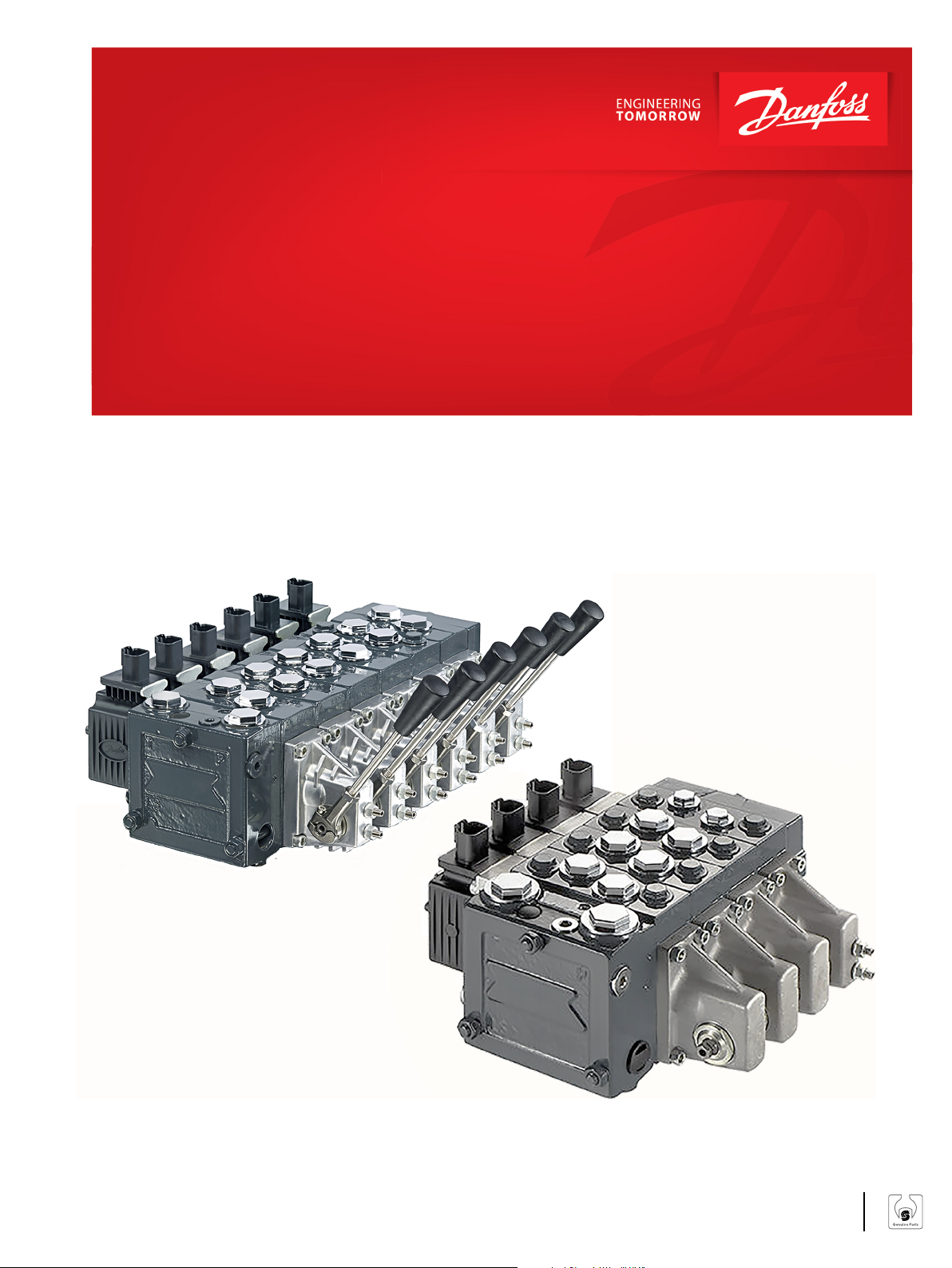
Service Manual
PVG 16 and 32 Assembly/Disassembly
Guide
PVG 16, PVG 32
www.danfoss.com
Service Manual
PVG 16 and 32 Service Assembly/Disassembly Guide
Revision history Table of revisions
Date Changed Rev
August 2018 Corrected typo on page 20 0107
November 2017 Minor text change 0106
February 2017 Uodated with PVE Series 7 0105
May 2014 Testing section added, cover image AD
Apr 2014 Converted to Danfoss layout – DITA CMS AC
Aug 2013 Torgue change in dwg, page 19 AB
Jun 2012 First Edition AA
2 | © Danfoss | August 2018 L1104530 | AX00000133en-US0107

Service Manual
PVG 16 and 32 Service Assembly/Disassembly Guide
Contents
General information
PVG general description................................................................................................................................................................ 4
Features of PVG 16 and PVG 32...................................................................................................................................................4
PVG modules .....................................................................................................................................................................................5
PVP, pump side modules overview...................................................................................................................................... 5
PVB, basic modules.....................................................................................................................................................................5
Actuation modules.....................................................................................................................................................................5
PVG 16, PVG 32 and Open Circuit Load Sense Example.....................................................................................................6
Load sensing controls.....................................................................................................................................................................7
LS control with bleed orifice (do not use with PVG valves)......................................................................................... 7
Integral PC function................................................................................................................................................................... 7
Load sensing system characteristics:...................................................................................................................................7
PVBS, main spools with pressure compensated control....................................................................................................8
Pressure compensated system characteristics.................................................................................................................8
Typical applications for pressure compensated systems.............................................................................................9
Remote pressure compensated controls.............................................................................................................................. 10
Remote pressure compensated system characteristics:............................................................................................ 10
Typical applications for remote pressure compensated systems:..........................................................................10
Open center PVP............................................................................................................................................................................ 11
Closed center PVP..........................................................................................................................................................................11
Sectional view
Safety in Application
Example of a control system for manlift................................................................................................................................13
Examples of wiring block diagram.....................................................................................................................................15
Assembly instructions
PVG 16 and 32 general conditions...........................................................................................................................................17
Assembly...........................................................................................................................................................................................17
Testing
PVG 16 and 32 leak test................................................................................................................................................................22
Pressure setting after assembly................................................................................................................................................22
PVG 16 and 32 function testing................................................................................................................................................ 23
Recommended equipment and hand tools to assemble PVG 16 and PVG 32:..................................................24
Test report
Order specifications
©
Danfoss | August 2018 L1104530 | AX00000133en-US0107 | 3
Service Manual
PVG 16 and 32 Service Assembly/Disassembly Guide
General information
PVG general description
PVG is a hydraulic, load-sensing proportional valve, designed for optimal machine performance and
maximum design flexibility.
The PVG valve design is based on a modular concept that enables machine designers to specify a valve
solution suitable for multiple market segments across multiple applications.
The load independent proportional control valve and high performance actuator technology combined
with a low pressure drop design improves the machine performance and efficiency – increasing
productivity and reducing energy consumption.
Features of PVG 16 and PVG 32
Load-independent flow control:
•
Oil flow to an individual function is independent of the load pressure of this function
‒
Oil flow to one function is independent of the load pressure of other functions
‒
Good regulation characteristics
•
Energy-saving
•
Up to 12 basic modules per valve group
•
Several types of connection threads
•
Low weight
•
Compact design and installation
•
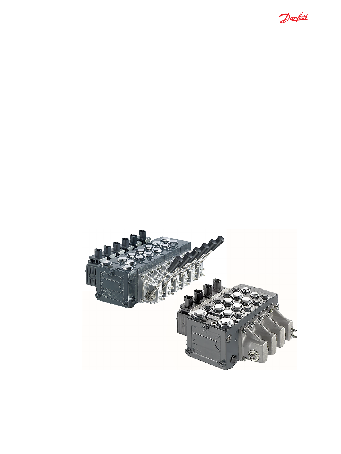
PVG 32 and PVG 16
4 | © Danfoss | August 2018 L1104530 | AX00000133en-US0107

Service Manual
PVG 16 and 32 Service Assembly/Disassembly Guide
General information
PVG modules
PVP, pump side modules overview
Built-in pressure relief valve
•
Pressure gauge connection
•
Versions:
•
Open center version for systems with fixed displacement pumps
‒
Closed center version for systems with variable displacement pumps
‒
Pilot oil supply for electrical actuator built into the pump side module
‒
Pilot oil supply for hydraulic actuation built into the pump side module
‒
Versions prepared for electrical LS unloading valve PVPX
‒
PVB, basic modules
Interchangeable spools
•
Depending on requirements the basic module can be supplied with:
•
Integrated pressure compensator in channel P
‒
Load holding check valve in channel P
‒
Shock/suction valves for A and B ports
‒
LS pressure limiting valves individually adjustable for ports A and B
‒
Different interchangeable spool variants
‒
All versions suitable for mechanical, hydraulic and electrical actuation
‒
Actuation modules
The basic module is always fitted with mechanical actuator PVM and PVMD, which can be combined with
the following as required:
Electrical actuator (11 - 32 V ===):
•
PVES – proportional, Super
‒
PVEH – proportional, High performance
‒
PVEH-F – proportional high performance, Float
‒
PVEA – proportional low hysteresis
‒
PVEM – proportional, Medium performance
‒
PVEO – ON/OFF
‒
PVEH-U/PVES-U – proportional, voltage control, 0-10 V
‒
PVED-CC – Digital CAN controlled J1939/ISOBUS
‒
PVED-CX – Digital CAN controlled CANopen X-tra safety
‒
PVEP – PWM voltage controlled (11-32 V)
‒
PVHC – High Current actuator for PVG
‒
PVMR, cover for Mechanical detent
•
PVMF, cover for Mechanical Float
•
PVH, cover for Hydraulic actuation
•
©
Danfoss | August 2018 L1104530 | AX00000133en-US0107 | 5
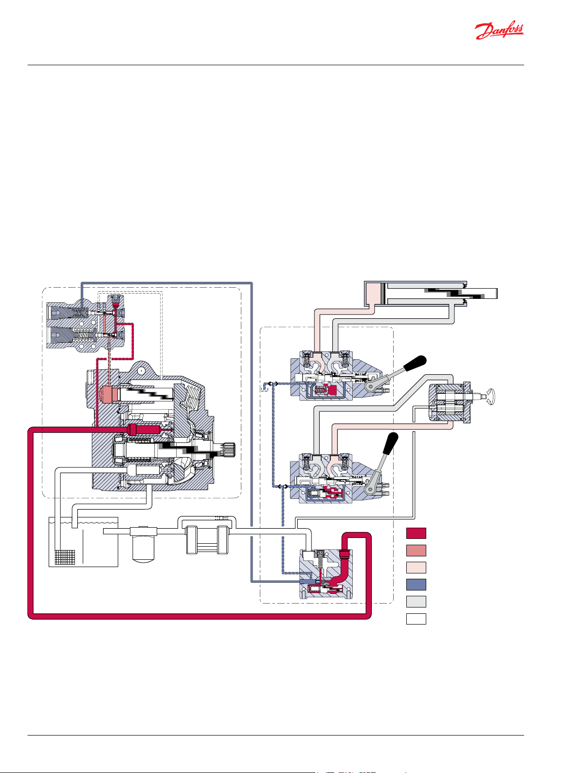
System pressur e
Servo pressur e
Actuator pressur e
Load sense pressur e
Actuator retur n
Suction / case drain /
system retur n
K/L Frame Series 45
open circuit axial
piston pump with
load sensing contro l
PVG 32
multi-sec tion
load
sensing
contro l
valve
P101 658E
Reservoir
Filter
Heat exchanger
Double-ac ting cylinder
Bi-directional
gear moto r
Service Manual
PVG 16 and 32 Service Assembly/Disassembly Guide
General information
PVG 16, PVG 32 and Open Circuit Load Sense Example
The pump receives fluid directly from the reservoir through the inlet line. A screen in the inlet line
protects the pump from large contaminants. The pump outlet feeds directional control valves such as
PVG-32’s, hydraulic integrated circuits (HIC), and other types of control valves. The PVG valve directs and
controls pump flow to cylinders, motors and other work functions. A heat exchanger cools the fluid
returning from the valve. A filter cleans the fluid before it returns to the reservoir.
Flow in the circuit determines the speed of the actuators. The position of the PVG valve spool determines
the flow demand. A hydraulic pressure signal (LS signal) communicates demand to the pump control. The
pump control monitors the pressure differential between pump outlet and the LS signal, and regulates
servo pressure to control the swashplate angle. Swashplate angle determines pump flow.
Actuator load determines system pressure. The pump control monitors system pressure and will decrease
the swashplate angle to reduce flow if system pressure reaches the PC setting. A secondary system relief
valve in the PVG valve acts as a back-up to control system pressure.
Pictorial circuit diagram
6 | © Danfoss | August 2018 L1104530 | AX00000133en-US0107
0
0
P101 968E
PC setting
Flow
Pressure
Q max
P101 967
Service Manual
PVG 16 and 32 Service Assembly/Disassembly Guide
General information
Load sensing controls
The LS control matches system requirements for both pressure and flow in the circuit regardless of the
working pressure. Used with a closed center control valve, the pump remains in low-pressure standby
mode with zero flow until the valve is opened. The LS setting determines standby pressure.
Typical operating curve
Most load sensing systems use parallel, closed center, control valves with special porting that allows the
highest work function pressure (LS signal) to feed back to the LS control.
Margin pressure is the difference between system pressure and the LS signal pressure. The LS control
monitors margin pressure to read system demand. A drop in margin pressure means the system needs
more flow. A rise in margin pressure tells the LS control to decrease flow.
LS control with bleed orifice (do not use with PVG valves)
The load sense signal line requires a bleed orifice to prevent high-pressure lockup of the pump control.
Most load-sensing control valves include this orifice. An optional internal bleed orifice is available, for use
with control valves that do not internally bleed the LS signal to tank.
Load sensing circuit
Integral PC function
The LS control also performs as a PC control, decreasing pump flow when system pressure reaches the PC
setting. The pressure compensating function has priority over the load sensing function.
For additional system protection, install a relief valve in the pump outlet line.
Load sensing system characteristics:
Variable pressure and flow
•
Low pressure standby mode when flow is not needed
•
System flow adjusted to meet system requirements
•
Lower torque requirements during engine start-up
•
Single pump can supply flow and regulate pressure for multiple circuits
•
Quick response to system flow and pressure requirements
•
©
Danfoss | August 2018 L1104530 | AX00000133en-US0107 | 7

0
0
Q max
Pressure
Fl
ow
P101 166E
PC setting
P101 965
Service Manual
PVG 16 and 32 Service Assembly/Disassembly Guide
General information
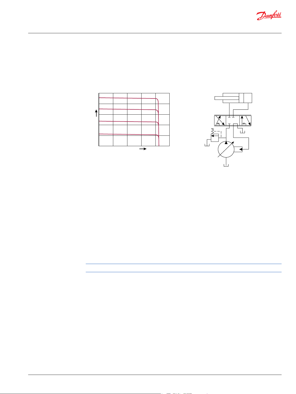
PVBS, main spools with pressure compensated control
The PC control maintains constant system pressure in the hydraulic circuit by varying the output flow of
the pump. Used with a closed center control valve, the pump remains in high pressure standby mode at
the PC setting with zero flow until the function is actuated.
Typical operating curve
Simple closed center circuit
Once the closed center valve is opened, the PC control senses the immediate drop in system pressure
and increases pump flow by increasing the swashplate angle.
The pump continues to increase flow until system pressure reaches the PC setting.
If system pressure exceeds the PC setting, the PC control reduces the swashplate angle to maintain
system pressure by reducing flow. The PC control continues to monitor system pressure and changes
swashplate angle to match the output flow with the work function pressure requirements.
If the demand for flow exceeds the capacity of the pump, the PC control directs the pump to maximum
displacement. In this condition, actual system pressure depends on the actuator load.
For additional system protection, install a relief valve in the pump outlet line.
Pressure compensated system characteristics
Constant pressure and variable flow
•
High pressure standby mode when flow is not needed
•
System flow adjusts to meet system requirements
•
Single pump can provide flow to multiple work functions
•
Quick response to system flow and pressure requirements
•
8 | © Danfoss | August 2018 L1104530 | AX00000133en-US0107

Service Manual
PVG 16 and 32 Service Assembly/Disassembly Guide
General information
Typical applications for pressure compensated systems
Constant force cylinders (bailers, compactors, refuse trucks)
•
On/off fan drives
•
Drill rigs
•
Sweepers
•
Trenchers
•
©
Danfoss | August 2018 L1104530 | AX00000133en-US0107 | 9

0
0
Q max
Pressure
Fl
ow
P101 969E
PC setting
Remote PC setting
P101 966
Service Manual
PVG 16 and 32 Service Assembly/Disassembly Guide
General information
Remote pressure compensated controls
The remote PC control is a two-stage control that allows multiple PC settings. Remote PC controls are
commonly used in applications requiring low and high pressure PC operation.
Typical operating curve
The remote PC control uses a pilot line connected to an external hydraulic valve. The external valve
changes pressure in the pilot line, causing the PC control to operate at a lower pressure. When the pilot
line is vented to reservoir, the pump maintains pressure at the load sense setting.
When pilot flow is blocked, the pump maintains pressure at the PC setting. An on-off solenoid valve can
be used in the pilot line to create a low-pressure standby mode. A proportional solenoid valve, coupled
with a microprocessor control, can produce an infinite range of operating pressures between the low
pressure standby setting and the PC setting.
Size the external valve and plumbing for a pilot flow of 3.8 l/min [1 US gal/min]. For additional system
protection, install a relief valve in the pump outlet line.
Closed center circuit with remote PC
Remote pressure compensated system characteristics:
Constant pressure and variable flow
•
High or low pressure standby mode when flow is not needed
•
System flow adjusts to meet system requirements
•
Single pump can provide flow to multiple work functions
•
Quick response to system flow and pressure requirements
•
Typical applications for remote pressure compensated systems:
Modulating fan drives
•
Anti-stall control with engine speed feedback
•
Front wheel assist
•
Road rollers
•
Combine harvesters
•
Wood chippers
10 | © Danfoss | August 2018 L1104530 | AX00000133en-US0107
•

Service Manual
PVG 16 and 32 Service Assembly/Disassembly Guide
General information
Open center PVP
Description of the example: PVG 32 with open center PVP (fixed displacement pump) and PVB with flow
control spool.
When the pump is started and the main spools in the individual basic modules (11) are in the neutral
position, oil flows from the pump, through connection P, across the pressure adjustment spool (6) to
tank. The oil flow led across the pressure adjustment spool determines the pump pressure (stand-by
pressure).
When one or more of the main spools are actuated, the highest load pressure is fed through the shuttle
valve circuit (10) to the spring chamber behind the pressure adjustment spool (6), and completely or
partially closes the connection to tank to maintain pump pressure. Pump pressure is applied to the righthand side of the pressure adjustment spool.
The pressure relief valve (1) will open when the load pressure exceed the set value, diverting pump flow
back to tank.
In a pressure-compensated basic module the compensator (14) maintains a constant pressure drop
across the main spool – both when the load changes and when a module with a higher load pressure is
actuated.
With a non pressure-compensated basic module incorporating a load drop check valve (18) in channel P,
the check valve prevents return oil flow.
The basic module can be supplied without the load drop check valve in channel P for functions with overcenter valves.
The shock valves PVLP (13) with fixed setting and the suction valves PVLA (17) on ports A and B are used
for the protection of the individual working function against overload and/or cavitation.
An adjustable LS pressure limiting valve (12) can be built into the A and B ports of pressure-compensated
basic modules to limit the pressure from the individual working functions. The LS pressure limiting valves
save energy compared with:
PVLP all the oil flow to the working function will be led across the combined shock and suction valves
•
to tank if the pressure exceeds the fixed setting.
LS pressure limiting valves an oil flow of about 2 l/min [0.5 US gal/min] will be led across the LS
•
pressure limiting valve to tank if the pressure exceeds the valve setting.
Please see the sectional drawing Sectional view on page 12 for better understanding of this example.
Closed center PVP
Description of the example: PVG 32 with closed center PVP (variable displacement pump) and PVB with
flow control spool.
In the closed center version of PVP an orifice (5) and a plug (7) have been fitted instead of the plug (4).
This means that the pressure adjustment spool (6) will open to tank when the pressure in channel P
exceeds the set value of the pressure relief valve (1). The pressure relief valve in PVP should be set at a
pressure of approx. 30 bar [435 psi] above maximum system pressure (set on the pump or external
pressure relief valve).
In load sensing systems the load pressure is led to the pump control via the LS connection (8). In the
neutral position the pump load sense control sets the displacement so that leakage in the system is
compensated, to maintain the set stand-by pressure. When a main spool is actuated the pump load sense
control will adjust the displacement so that the set differential pressure (margin) between P and LS is
maintained.
Please see the sectional drawing Sectional view on page 12 for better understanding of this example.
©
Danfoss | August 2018 L1104530 | AX00000133en-US0107 | 11

1
2
3
4
6
7
9
8
T P
M
A
LS
B A
12
13
11
10
14
16
17
15
T T
LS
B
LS
A
B A
P
T T
B
19
P
18
20
V310106.A
PVP
PVB
PVB
5
Service Manual
PVG 16 and 32 Service Assembly/Disassembly Guide
Sectional view
1. Pressure relief valve 11. Main spool
2. Pressure reduction valve for pilot oil supply 12. LS pressure limiting valve
3. Pressure gauge connection 13. Shock and suction valve, PVLP
4. Plug, open center 14. Pressure compensator
5. Orifice, closed center 15. LS connection, port A
6. Pressure adjustment spool 16. LS connection, port B
7. Plug, closed center 17. Suction valve, PVLA
8. LS connection 18. Load drop check valve
9. LS signal 19. Pilot oil supply for PVE
10. Shuttle valve 20. Maximum oil flow adjustment screws for A/B ports
12 | © Danfoss | August 2018 L1104530 | AX00000133en-US0107

W
Service Manual
PVG 16 and 32 Service Assembly/Disassembly Guide
Safety in Application
All types of control valves (incl. proportional valves) can fail, thus the necessary protection against the
serious consequences of function failure should always be built into the system. For each application an
assessment should be made for the consequences of pressure failure and uncontrolled or blocked
movements.
To determine the degree of protection that is required to be built into the application, system tools such
an FMEA (Failure Mode and Effect Analysis) and Hazard and Risk Analysis can be used.
FMEA – IEC EN 61508
FMEA (Failure Mode and Effect Analysis) is a tool used for analyzing potential risks. This analytical
technique is utilized to define, identify, and prioritize the elimination or reduction of known and/or
potential failures from a given system before it is released for production. Please refer to the standard IEC
FMEA 61508.
Hazard and risk analysis ISO 12100-1/14121
This analysis is a tool used in new applications as it will indicate whether there are special safety
considerations to be met according to the machine directives EN 13849. Dependent on the determined
levels conformity this analysis will detirmine if any extra requirements for the product design,
development process, production process or maintenance, example the complete product life cycle.
Warning
All brands and all types of directional control or proportional valves, which are used in many different
operation conditions and applications, can fail and cause serious damage.
Analyze all aspects of the application. The machine builder/system integrator alone is responsible for
making the final selection of the products and assuring that all performance, safety and warning
requirements of the application are met. The process of choosing the control system and safety levels is
governed by the machine directives EN 13849 (Safety related requirements for control systems).
Example of a control system for manlift
Example of a control system for man-lift
©
Danfoss | August 2018 L1104530 | AX00000133en-US0107 | 13

W
Service Manual
PVG 16 and 32 Service Assembly/Disassembly Guide
Safety in Application
Example of a control system for man-lift using PVE Fault monitoring input signals and signals from
external sensors to ensure the PLUS+1® main controllers correct function of the man-lift.
Typical PVE wiring block diagram
Warning
It is the responsibility of the equipment manufacturer that the control system incorporated in the
machine is declared as being in conformity with the relevant machine directives.
14 | © Danfoss | August 2018 L1104530 | AX00000133en-US0107

Fault detection output
high=on
low=off
Alarm
logic
2)
Memory3)
E1
E2
Output
AND
OR
U
DC2
Error
U
S
Neutral detection / Supply control
signal
≠
neutral
OFF
Delay
1)
U
DC2
Error
U
S
PVEH
with AMP
connector
PVEH
with AMP
connector
Hydraulic
deactivation
Neutral detection / Supply control
signal
≠
neutral
OFF
Delay
1)
PVE 1
PVE 2
Emergency
stop
Man present
switch
C
C
D
B
B
A
P301 318
Service Manual
PVG 16 and 32 Service Assembly/Disassembly Guide
Safety in Application
PVG 32 – used in system with fixed displacement pumps:
•
PVSK, commonly used in crane application - full flow dump
•
PVPX, LS dump to tank
PVG 100 – alternative LS dump/pilot supply disconnect:
•
PVPP, pilot oil supply shut off
•
External cartridge valve connecting LS pressure or main pressure to tank
PVG 120 – pump disconnect/block for variable pumps:
•
PVPE, full flow dump for the PVG 120
•
External cartridge valve connecting LS pressure to tank
Examples of wiring block diagram
Example 1
Typical wiring block diagram using PVEH with neutral power off switch and fault monitoring output for
hydraulic deactivation.
©
Danfoss | August 2018 L1104530 | AX00000133en-US0107 | 15

W
Neutral detection / Supply control
signal
≠
neutral
OFF
Delay
1)
Fault detection output
PVEH-DI
AMP supply
connector
PVEH-DI
AMP supply
connector
PVEH-DI
AMP connector
PVEH-DI
AMP connector
AND
high=on
low=off
Neutral detection / Supply control
signal
≠
neutral
OFF
Delay
1)
PVE 1
PVE 2
Fault detection
Delay
DI
Logic
Memory
U
S
DI-A
DI-B
2)
4)
3)
Output
Fault detection
Delay
DI
Logic
Memory
U
S
DI-A
DI-B
2)
4)
3)
Output
OR
Emergency
Stop
Man present
switch
P301 319
U
DC2
Error
U
S
DI-B
Error
DI-A
U
DC2
Error
U
S
Error
DI-A
Hydraulic
deactivation
W
Service Manual
PVG 16 and 32 Service Assembly/Disassembly Guide
Safety in Application
A Emergency stop / man present switch
B PVE Fault monitoring signals
C Neutral signal detection
D Deactivation of the hydraulic system (System Control Logic, example: PLUS+1® for signal monitoring
and triggering signal)
Warning
It is the responsibility of the equipment manufacturer that the control system incorporated in the
machine is declared as being in conformity with the relevant machine directives.
Example 2
Fault monitoring for deactivation of the hydraulic system with extra fault inputs using the PVE’s with DI
(Direction Indication) function. System Control Logic, example PLUS+1® for signal monitoring and
triggering signal for deactivation of the hydraulic system.
Warning
It is the responsibility of the equipment manufacturer that the control system incorporated in the
machine is declared as being in conformity with the relevant machine directives.
16 | © Danfoss | August 2018 L1104530 | AX00000133en-US0107

Service Manual
PVG 16 and 32 Service Assembly/Disassembly Guide
Assembly instructions
PVG 16 and 32 general conditions
The specification sheet is compiled by the sales department for assembly of a new PVG 16 and PVG 32
valve groups.
1. Before, during and after the assembly/disassembly of new PVG groups, absolute cleanliness and care
must be observed with regard to internal and external parts of the units concerned.
2. Use non-volatile, petroleum based solutions for cleaning valves and/or modules.
3. Replace all parts considered likely to cause malfunction during subsequent testing.
4. Replace all loose O-rings (without exceptions) with new O-rings.
5. Lubricate all moving parts with hydraulic oil before assembly.
6. Lubricate all O-rings with petroleum jelly.
Refer to Service Manual 520L0515 for module designations, item and spare parts numbers.
Assembly
The basic assembly sequence for PVG 16 and PVG 32 group is as follows:
1. Starting from the end plate place the module with (PVS, PVSP, PVSK ) the tie rod bolts with the long
threaded end pointing upwards ready for mounting of PVB modules.
2. Place all lubricated O-rings in their respective grooves in the different modules.
3. Locate the basic modules (PVB) against the PVP (PVS, PVSP, PVSK) using the tie rod bolts for
alignment between the PVP and the PVB modules making sure the LS shuttle valve is able to move
freely.
4. Place the PVP (the PVS if a valve group has midinlet, or HIC) as the last module and place the washers
and nuts in position and hand tighten the valve.
5. Place the valve on a plain and level surface and tighten the assembly to a torque of 28 ±2 N•m (247.8
±17 lbf•in) using a 13 mm socket. Max. level tolerance is 0.5 mm per section e.g. this means with 8 PVB
sections max. allowable height difference between the mounting holes would be 4 mm (this would
also be seen as a twist in the valve group assembly).
The valve assembly is to be assembled in accordance with the specification sheet.
6. Install the spools (PVBS) into the PVB’s.
The assembled spool is marked with two four-digit numbers
The number in the end of the spool where the plug is fitted, “B”, is the drawing number of the spool
and indicates that this end must face towards the “B” port of the valve.
The other number, stamped on the side the PVBS pull rod “A”, is the module number of the
assembled main spool.
For spool assemblies with remote hydraulic spools, the centering spring is different. The standard
spring has a wire diameter of 1.9 mm. The remote hydraulic spring (5-15 bar) has a wire diameter of
2.8 mm.
©
Danfoss | August 2018 L1104530 | AX00000133en-US0107 | 17

PVEO
PVEA
PVEA-F
PVMD
PVH
PVM
PVP
PVB
PVS
D
C
E
F
G
V310395.B
Service Manual
PVG 16 and 32 Service Assembly/Disassembly Guide
Assembly instructions
PVG 16 and PVG 32 are symmetrical, which allows for valve groups to be “option mounted” This can
be one by inserting the spools from the “B” port side and mounting the PVM’s on the “B” port side of
the PVB assembly.
7. Assemble the mechanical actuators to the valve (see the figure below). Before fitting the PVM into
engagement with the PVBS tension rod, the driver arm must be pushed towards the PVB before
engagement will occur.
Once the driver arm is engaged, rotate the mechanical actuator while pressing the PVM until the PVM
is flush against the PVB housing.
Tighten the four (4) mounting screws to a torque of 0.8 +0/-0.5 N•m [70 +0/-4.5 lbf•in] using a 5 mm
hex driver.
Assembly of PVE, electrical actuation / Assembly of PVM, mechanical actuation
Assembly of PVG 16
18 | © Danfoss | August 2018 L1104530 | AX00000133en-US0107

P109129
Flow P
A
w: P
B
6±1Nm[53±9lbf-in]
6±1Nm[53±9lbf-in]
w: P
A
PVM
PVS
PVBZ
B
A
PVB
PVP
PVEA/PVEM
PVEO
PVEH/PVES
PVH
PVMD
PVMR/PVMF
Service Manual
PVG 16 and 32 Service Assembly/Disassembly Guide
Assembly instructions
Assembly of PVG 32
8. Assemble the actuators. The manual cover PVMD or the remote hydraulic end cover must be installed
with the arrow pointing upwards towards the “A/B” port.
The PVE’s must be installed with the connectors pointing upwards towards the “A/B” port. The torque
for the four (4) mounting screws is 0.8 + 0/-0.5 N•m [70 +0/-4.5 in. lbs.] using a 5 mm hex drive.
Common to all types of PVE’s is a small nylon filter in the “P” channel, under the O-ring. Insure that the
transducer stem on the PVE’s with closed loop feedback interfaces with the end of the PVBS without
any restrictions.
New and unused PVE units can be mounted without neutral adjustment to the LVDT transducer. If an
adjustment is required, contact the service department.
For control options with mechanical detent (PVMR) or mechanical float (PVMF) function, please follow
instructions in the previous section describing assembly of the PVMD or PVH remote with reference
to the below pictures.
Assembly of the actuators
©
Danfoss | August 2018 L1104530 | AX00000133en-US0107 | 19

Service Manual
PVG 16 and 32 Service Assembly/Disassembly Guide
Assembly instructions
For torque tighting values of the large hexagon (Y) with the detent assembly function, please see the
table below.
Tightening torques and widths across flats
X Y Z
With across flats
Tightening torque 8 ±0.5 N•m
[70 ±4.5 lbf•in]
15 ±2 N•m
[135 ±20 lbf•in]
4 ±1 N•m
[35 ±9 lbf•in]
PVMR, detent option without a neutral spring PVMF, mechanical float option
The valve assembly is to be assembled in accordance with the specification sheet.
9. Assemble the shock/check (PVLP) valves into the PVB’s. The top of the PVLP valve is marked with the
last three digits of the module code number. This number also indicates the valve pressure setting @
15.1 I/min [4 US gal/min]. Be careful not to swap plugs and valves. The PVLA module carries no
markings. The torque for the plug is 40.0 ± 0.3 N•m [355 ± 25 lbf•in].
20 | © Danfoss | August 2018 L1104530 | AX00000133en-US0107

PVM
PVS
PVBZ
PVB
PVP
PVEA/PVEM
PVEO
PVEH/PVES
PVH
PVMD
PVMR/PVMF
PVLP/PVLA
C
D
F
E
Service Manual
PVG 16 and 32 Service Assembly/Disassembly Guide
Assembly instructions
10. Issue/attach label with PVG code no. for the valve assembly.
©
Danfoss | August 2018 L1104530 | AX00000133en-US0107 | 21

PVP LS
P
6.9 bar [100 psi]
V310343.A
6.4 ± 1 bar
[93 ± 14.5 psi]
T
A B A B A B
LX
PVB PVB PVB PVS/I
Service Manual
PVG 16 and 32 Service Assembly/Disassembly Guide
Testing
PVG 16 and 32 leak test
After all components have been assembled and tightened to the proper specifications, a leak test with
compressed air must be performed.
1. Block off all “A” and “B” ports with steel plugs.
2. Block off the “P” port with a steel plug in the PVP. Screw the compressed air connection into the “T”
port. (see the figure below).
Block diagram
3. Apply compressed air at 6.9 bar [100 psi] for 5 minutes. At the same time, activate all PVM control
levers in order to fill fill all channels, chambers and cavities with an air.
4. Shut off the compressed air so that pressure is confined in the entire valve.
The permissible pressure drop in the valve is 0.5 bar [7 psi] per minute maximum. Small leaks can be
traced by pouring a small amount of oil onto the place where the leak is thought to be present.
5. Try correcting small leaks by retightening the assembly. Large leaks usually indicate forgotten or
squeezed O-rings.
Pressure setting after assembly
All relief valves must be set with a gauge located in the gauge port of the PVP.
Groups with CLOSED CENTER PVP’S can be tested as assembled for all pressure relief settings.
•
Groups with OPEN CENTER PVP’S and PVB’S with shock valves (PVLP) and LSA/LSB valves with opening
•
pressure lower than the pressure setting in the PVP. The PVP must be modified temporarily to
CLOSED CENTER. After the relief settings are made, the PVP must be corrected to OPEN CENTER. All
other with OPEN CENTER PVP’S can be tested as assembled.
The PVP and LSA/LSB pressure relief valves must be set by applying oil pressure on the “P” port in the
•
PVP. The “T” port must be connected to tank.
All “A” and “B” ports must be blocked off with steel plugs.
•
The quantity of oil supplied to the valve assembly must be at least 15 +/- 2 L/min [4 +/- 0.45 US gal/
•
min].
The CLOSED CENTER PVP module can be set by applying pressure to the “P” port.
•
The OPEN CENTER PVP module can be set by applying pressure to the “P” port and activating the
•
spool in the A or B direction dead headeding the A or B port.
It is assumed that the PVP module has a higher setting than the LSA/LSB valves. LSA/LSB valves must
•
be set one at a time by activating the spool in the PVB section in the direction of the LS valve to be
adjusted.
Adjustment of the relief valve is accomplished by using a 4 mm hex wrench.
•
22 | © Danfoss | August 2018 L1104530 | AX00000133en-US0107

P109140
C
LS
A
C
C
LS
B
C
C
LS
C
T
6[0.24]
360º~1450 psi
360º~100 bar
C-C
4[0.16]
360º~1740 psi
360º~120 bar
T
C-C
PVP
LS
P
V310340.A
Inlet Pressure Measurement
30 to 350 bar
[435 to 5075 psi]
Workport PVLP Pressure Measurement
32 to 350 bar [464 to 5075 psi]
PC Pump 14 l/min
[3.4 US gal/min]
T
A B A B A B
LX
PVB PVB PVB PVS/I
Service Manual
PVG 16 and 32 Service Assembly/Disassembly Guide
Testing
For relief valve version and location please see the figure
PVG 16 and 32 function testing
Function testing insures the correct dynamic manual and electrical operation of the PVG 16 and PVG 32
valve assembly. This test should be performed after completing the pressure adjustments. Each section of
the assembly must be tested:
1. With the pump connected, remove the plugs from the section to be tested as described in the
Pressure setting after assembly on page 22 section. Connect the “A” port of the valve to the rod end of
the cylinder and the “B” port to the base end of the cylinder (see the figure below).
©
Danfoss | August 2018 L1104530 | AX00000133en-US0107 | 23
2. Shift the control lever of the tested section towards the valve and observe cylinder retraction. Shift
the same control lever away from the valve and observe cylinder extension. Repeat several times. On
valve groups with PVM’s on the “B” side, the cylinder movement will be opposite when shifting the
handle in the same direction.
3. Check the spool travel smoothness in both directions.

Service Manual
PVG 16 and 32 Service Assembly/Disassembly Guide
Testing
4. Check the metering of the spool in both directions. Can you control the speed of the cylinder/motor,
slow/fast?
5. Check to see if the LS signal at the PVP drops off, when the spool is in the neutral position. This signal
also should not build up pressure in the neutral position.
6. Shift the spool to one direction manually and let go of the control lever. The valve should center itself.
If the control lever sticks in any position, check for binding of the spool. This is to be checked in both
directions.
7. Utilizing a controller package, connect the EL-PLUG connector to the PVE. Set the controller to the
corresponding PVE. Insure that the proper voltage and joystick are being used. Similar to manual
testing of the valve, eclectically shift the valve to allow flow out the “A” port.
Check to see if the PVM control level shifts in the correct direction. This should also be done in the “B”
direction. Check to insure that once the controller is not activated the valve centers itself. Observe
that the spool responds to any change in the signal from the joystick. Any change in position of the
joystick should relate to a change in the PVM control lever. Check the metering of the PVEM/H’s.
8. After all sections have been tested, insure that all relief valves are adjusted correctly. Refer to the
section Pressure setting after assembly on page 22 for any adjustments.
9. Remove all steel plugs, fittings and hoses. Drain the oil from the valve group. Install plastic plugs in all
ports & rubber cap (155L6377) over all pressure adjustments.
10. A certified PVG valve test report must be completed & accompany every valve, e.g. see PVG 32 Test
report on page 25 on the next page.
Sections with open ported spools will experience cylinder extension in the neutral position.
Recommended equipment and hand tools to assemble PVG 16 and PVG 32:
Socket driver, Allen wrench = 2.5, 3, 4, 5, 6, 8 mm.
•
Sockets = 3/8 drive deep well 13 mm.
•
Combo – wrenches = 10, 13 mm
•
Torque wrench = 3/8 drive 0 – 10 N•m [0-885 in. lbs.]
•
Ball driver hex = 4, 5, 6, 8 mm
•
Plastic hammer
•
24 | © Danfoss | August 2018 L1104530 | AX00000133en-US0107

Service Manual
PVG 16 and 32 Service Assembly/Disassembly Guide
Test report
©
Danfoss | August 2018 L1104530 | AX00000133en-US0107 | 25

Service Manual
PVG 16 and 32 Service Assembly/Disassembly Guide
Order specifications
PVG 16 specification sheet
26 | © Danfoss | August 2018 L1104530 | AX00000133en-US0107

Service Manual
PVG 16 and 32 Service Assembly/Disassembly Guide
Order specifications
PVG 32 specification sheet
©
Danfoss | August 2018 L1104530 | AX00000133en-US0107 | 27

Danfoss
Power Solutions GmbH & Co. OHG
Krokamp 35
D-24539 Neumünster, Germany
Phone: +49 4321 871 0
Danfoss
Power Solutions ApS
Nordborgvej 81
DK-6430 Nordborg, Denmark
Phone: +45 7488 2222
Danfoss
Power Solutions (US) Company
2800 East 13th Street
Ames, IA 50010, USA
Phone: +1 515 239 6000
Danfoss
Power Solutions Trading
(Shanghai) Co., Ltd.
Building #22, No. 1000 Jin Hai Rd
Jin Qiao, Pudong New District
Shanghai, China 201206
Phone: +86 21 3418 5200
Products we offer:
Comatrol
www.comatrol.com
Turolla
www.turollaocg.com
Hydro-Gear
www.hydro-gear.com
Daikin-Sauer-Danfoss
www.daikin-sauer-danfoss.com
Bent Axis Motors
•
Closed Circuit Axial Piston
•
Pumps and Motors
Displays
•
Electrohydraulic Power
•
Steering
Electrohydraulics
•
Hydraulic Power Steering
•
Integrated Systems
•
Joysticks and Control
•
Handles
Microcontrollers and
•
Software
Open Circuit Axial Piston
•
Pumps
Orbital Motors
•
PLUS+1® GUIDE
•
Proportional Valves
•
Sensors
•
Steering
•
Transit Mixer Drives
•
Danfoss Power Solutions is a global manufacturer and supplier of high-quality hydraulic and
electronic components. We specialize in providing state-of-the-art technology and solutions
that excel in the harsh operating conditions of the mobile off-highway market. Building on
our extensive applications expertise, we work closely with our customers to ensure
exceptional performance for a broad range of off-highway vehicles.
We help OEMs around the world speed up system development, reduce costs and bring
vehicles to market faster.
Danfoss – Your Strongest Partner in Mobile Hydraulics.
Go to www.powersolutions.danfoss.com for further product information.
Wherever off-highway vehicles are at work, so is Danfoss. We offer expert worldwide support
for our customers, ensuring the best possible solutions for outstanding performance. And
with an extensive network of Global Service Partners, we also provide comprehensive global
service for all of our components.
Please contact the Danfoss Power Solution representative nearest you.
Local address:
Danfoss can accept no responsibility for possible errors in catalogues, brochures and other printed material. Danfoss reserves the right to alter its products without notice. This also applies to products
already on order provided that such alterations can be made without changes being necessary in specifications already agreed.
All trademarks in this material are property of the respective companies. Danfoss and the Danfoss logotype are trademarks of Danfoss A/S. All rights reserved.
©
Danfoss | August 2018 L1104530 | AX00000133en-US0107
 Loading...