

Technical Information
PVG 16
Proportional Valve Group
www.danfoss.com
Technical Information
PVG 16 Proportional Valve Group
Revision history Table of revisions
Date Changed Rev
July 2021 Added part number for PVPX port plug 1104
January 2021 Minor change on page 79 (PVEO Technical Data) 1103
June 2020 Edited PVEO section 1102
May 2020 Major update - changes throughout, Changed document number from 'BC00000211'
to 'BC152986484323'
December 2018 Major rework of document: new sections added, data corrected. 0901
October 2018 'PVBS Main Spools' section reworked. 'Safety in Systems' and 'PVB Basic Modules
Accessories' sections added.
August 2018 Minor update - part number typo corrected 0702
May 2018 Major update. 0701
April 2018 Minor change for PVEA. 0602
January 2018 Major update. 0601
July 2017 Major update. 0501
February 2017 Major update. 0401
March 2016 Minor update in PVHC technical characteristics 0303
March 2016 Updated to Engineering Tomorrow design. 0302
February 2016 Drawing was updated in topic: How to select the correct spool 0301
September 2015 PVG 16 Step II 0200
Feb. 2013-Mar. 2015 Major layout revision, drawings change BA-BF
October 2012 New Edition AA
1101
0801
2 | © Danfoss | July 2021 BC152986484323en-001104

Technical Information
PVG 16 Proportional Valve Group
Contents
General Information
General Description.........................................................................................................................................................................5
PVG 16 Features................................................................................................................................................................................ 5
Safety in Systems..............................................................................................................................................................................6
PVG 16 Modules Overview............................................................................................................................................................8
PVP Inlet Modules
Open Center PVP............................................................................................................................................................................10
Open Center PVP with PPRV...................................................................................................................................................... 13
Open center PVP with HPCO and PVE PPRV.........................................................................................................................17
Closed Center PVP......................................................................................................................................................................... 20
Closed Center PVP with PPRV....................................................................................................................................................22
Closed center PVPV with PPRV..................................................................................................................................................25
Closed center PVPVM with PPRV..............................................................................................................................................27
Open/Closed center PVP with PPRV........................................................................................................................................29
Open/Closed center PVPM......................................................................................................................................................... 32
PVP Inlet Module Accessories
PVPX Electrical LS Pressure Unloading Valve.......................................................................................................................33
Part numbers for PVPX............................................................................................................................................................34
PVPC without Check Valve..........................................................................................................................................................36
PVPC with Check Valve................................................................................................................................................................ 38
PVB Basic Modules
Compensated PVB.........................................................................................................................................................................41
Compensated PVB with PVLP/PVLA........................................................................................................................................44
Compensated PVB with LS A/B................................................................................................................................................. 48
Uncompensated PVB....................................................................................................................................................................52
Uncompensated PVB with PVLP...............................................................................................................................................55
PVLP Shock and Anti-Cavitation Valve...................................................................................................................................58
PVB Basic Modules Accessories
PVLP Shock and Anti-Cavitation Valve...................................................................................................................................61
PVLA Suction Valve........................................................................................................................................................................63
PVBS Main Spools
PVBS Fluid Flow Characteristics - Theoretical Performance...........................................................................................65
PVBS Main Spools Part Numbers
Flow Control Spools - Closed Neutral Position....................................................................................................................68
Flow Control Spools - Throttled Open Neutral Position.................................................................................................. 69
Flow Control Spools - Open/Closed Neutral Position.......................................................................................................70
PVG 16 Actuation
PVM Manual Actuation................................................................................................................................................................ 71
PVMD Cover................................................................................................................................................................................72
PVH Hydraulic Actuation.............................................................................................................................................................73
PVHC Electro-Hydraulic Actuation...........................................................................................................................................75
PVE Electro-hydraulic Actuation...............................................................................................................................................77
PVEO................................................................................................................................................................................................... 79
PVEO Technical Data............................................................................................................................................................... 81
PVEA Series 6 Proportional Control Actuator...................................................................................................................... 82
PVEA Technical Data................................................................................................................................................................83
PVG 16 connector variants......................................................................................................................................................... 85
Fault Monitoring and Reaction
Generic Fault Reaction.................................................................................................................................................................86
Fault Reaction Overview..............................................................................................................................................................87
PVS End Plates
PVS/PVSI ........................................................................................................................................................................................... 89
PVS/PVSI with LX-connection....................................................................................................................................................91
PVSI with P-, T-, LX- and M-connection..................................................................................................................................93
©
Danfoss | July 2021 BC152986484323en-001104 | 3

Technical Information
PVG 16 Proportional Valve Group
Contents
PVST with T-connection...............................................................................................................................................................95
PVAS Stay Bolts
PVAS Part Numbers.......................................................................................................................................................................98
PVG 16 modules total length and weight.............................................................................................................................98
PVG 32/16 Combinations............................................................................................................................................................99
PVG 256/128/32/16 Combinations....................................................................................................................................... 100
PVG 16 Combinations Valve Stack Dimensions
PVG 16 Dimensions.....................................................................................................................................................................102
PVG 32/16 Dimensions..............................................................................................................................................................103
PVG 100/16 Dimensions............................................................................................................................................................105
PVG 120/16 Dimensions............................................................................................................................................................107
PVG 128/16 Dimensions............................................................................................................................................................109
PVG 256/16 Dimensions............................................................................................................................................................111
PVG 16 Applications Schematics
PVG 16 Schematic with Basic End Plate...............................................................................................................................113
PVG 16 with P- and T-connection end plate......................................................................................................................114
4 | © Danfoss | July 2021 BC152986484323en-001104

Technical Information
PVG 16 Proportional Valve Group
General Information
General Description
PVG is a hydraulic, load-sensing proportional valve, designed for optimal machine performance and
maximum design flexibility. The PVG valve design is based on a modular concept that enables machine
designers to specify a valve solution suitable for multiple market segments across multiple applications.
The PVG 16 is a member of the PVG product platform and interfaces to other valve families enabling all
machine functions being controlled from one single valve stack.
PVG 16 controls work port flow up to 65 l/min [17 US gal/min] l/min and up to 420 bar [6090 psi] bar work
port pressure.
The load independent proportional control valve and high performance actuator technology combined
with a low pressure drop design improves the machine performance and efficiency – increasing
productivity and reducing energy consumption.
PVG 16 Features
PVG load-sensing proportional valves features and benefits summarized in bullets below:
Load-independent flow control:
•
Oil flow to an individual function is independent of the load pressure of this function
‒
Oil flow to one function is independent of the load pressure of other functions
‒
Inlet flow up to 140 l/min [37 US gal/min] 230 l/min [61 US gal/min] when used with mid-inlet
•
Easy integration with PVG 32
•
Possible combination with the rest of the PVG family, when using an interface module
•
Up to 12 basic modules per PVG 16 valve group
•
Reliable regulation characteristics across the entire flow range
•
Load sense relief valves for A and B port enables reduced energy loss at target pressure
•
Several options for connection threads and flange mount
•
Compact design, easy installation and serviceability
•
©
Danfoss | July 2021 BC152986484323en-001104 | 5
W
Technical Information
PVG 16 Proportional Valve Group
General Information
Safety in Systems
All types and brands of control valves, including proportional valves, can fail. Therefore, the necessary
protection against the serious consequences of a functional failure should always be built into the
system.
General safety considerations
For each application an assessment should be made for the consequences of the system in case of
pressure failure and uncontrolled or blocked movements.
Warning
Because the proportional valve is used in many different applications and under different operating
conditions, it is the sole responsibility of the manufacturer to ensure that all performance, safety and
warning requirements of the application is met in his selection of products and complies with relevant
machine specific and generic standards.
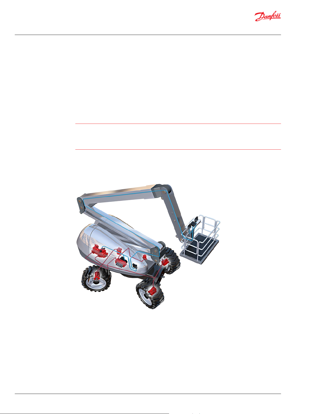
Control system example
An example of a control system using an aerial lift is shown below:
Aerial lift
This example breaks down the control system into smaller bits explaining the architecture in depth. Even
though many Danfoss components are used in the PVG control system.
The function of the control system is to use the output from the PVE together other external sensors to
ensure the PLUS+1 main controllers correct function of the aerial lift.
6 | © Danfoss | July 2021 BC152986484323en-001104
W
C
Technical Information
PVG 16 Proportional Valve Group
General Information
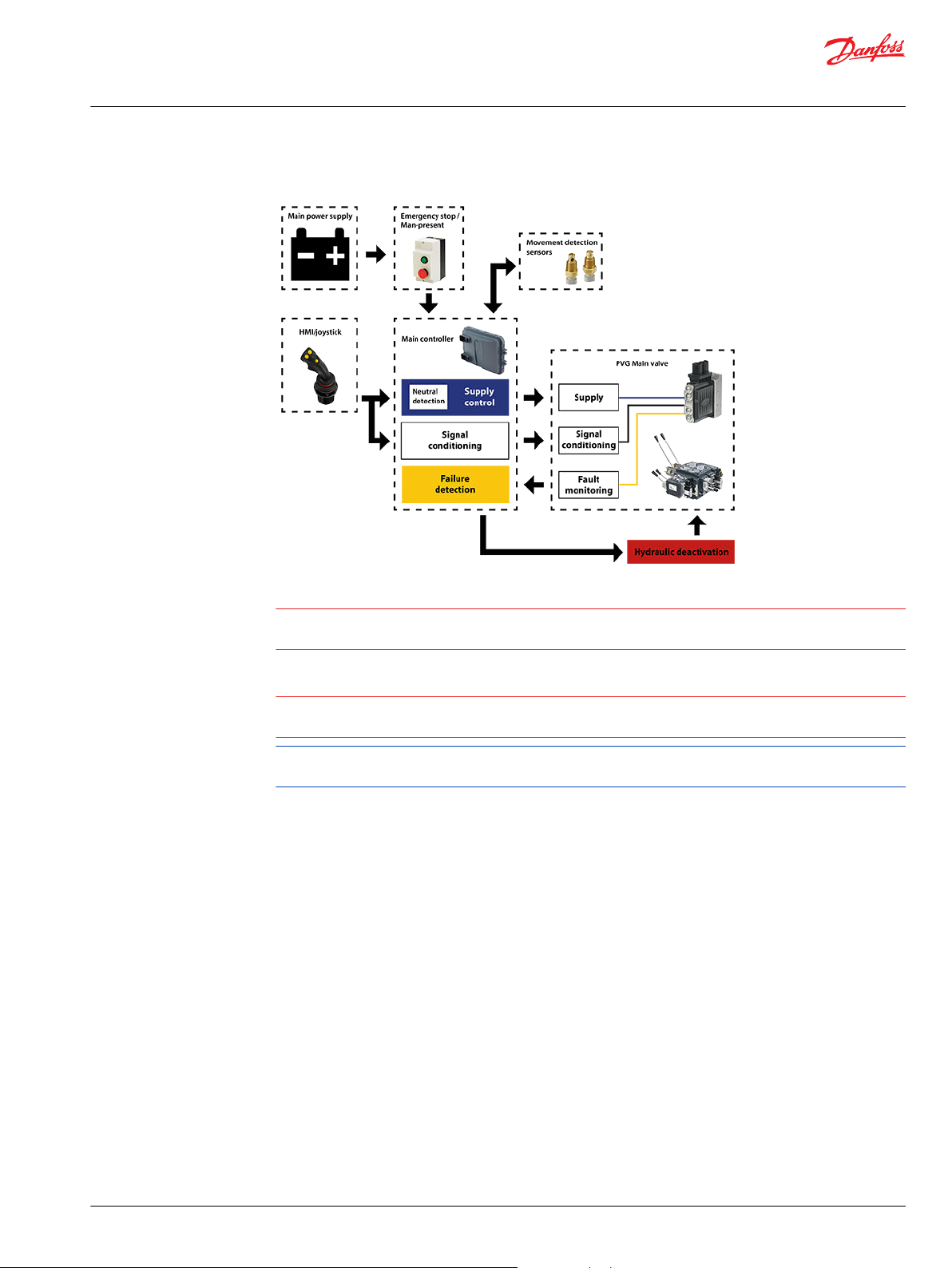
Electrical block diagram
Warning
It is the responsibility of the equipment manufacturer that the control system incorporated in the
machine is declared as being in conformity with the relevant machine directives.
Caution
A mix of electrical actuation and hydraulic actuation on the same valve stack is not safe. PVE and PVH are
designed for different pilot pressure.
Cost-free repairs, as mentioned in Danfoss General Conditions of Sale, are carried out only at Danfoss or
at service shops authorized by Danfoss.
©
Danfoss | July 2021 BC152986484323en-001104 | 7
PVM
PVP PVE
PVH/CoversPVBPVBS
PVS PVHC
PVAS
Technical Information
PVG 16 Proportional Valve Group
General Information
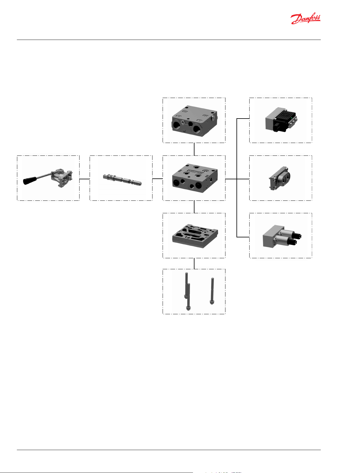
PVG 16 Modules Overview
PVG proportional valve group shown in the exploded view illustration for a quick modules navigation.
PVG 16 Modules Assembly Overview
PVG Modules Navigation:
PVP Inlet Modules on page 9
PVB Basic Modules on page 40
PVBS Main Spools on page 64
PVM Manual Actuation on page 71
PVE Electro-hydraulic Actuation on page 77
PVH Hydraulic Actuation on page 73
PVHC Electro-Hydraulic Actuation on page 75
PVS End Plates on page 88
PVAS Stay Bolts on page 97
8 | © Danfoss | July 2021 BC152986484323en-001104
112.5 [4.43]
110 [4.33]
95 [3.74]
23 [0.9]
48 [1.89]
Technical Information
PVG 16 Proportional Valve Group
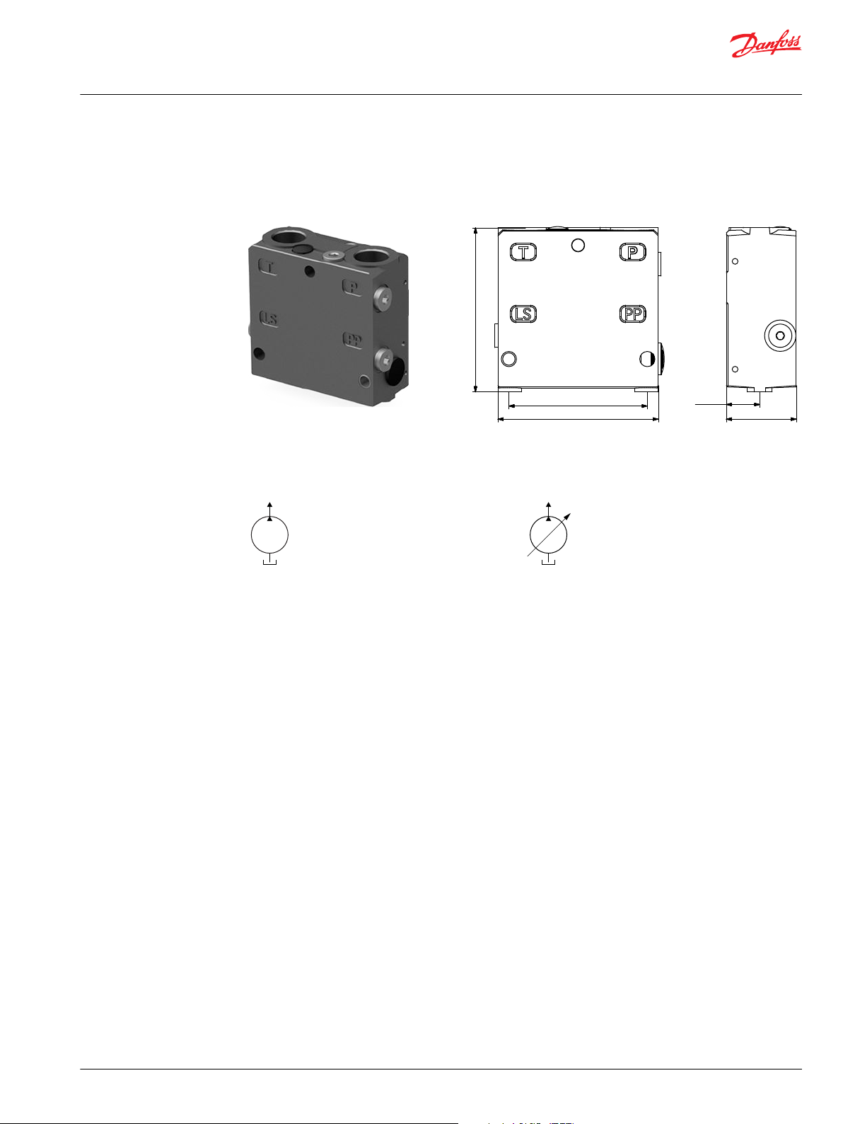
PVP Inlet Modules
The PVG 16 PVP inlet modules, also referred to as pump side modules, act as an interface between the
PVG 16 proportional valve group and the hydraulic pump and tank reservoir.
PVP Inlet Module PVP inlet module dimensions
Weight: 3.1 kg [6.9 lb]
Fixed displacement pump symbol Variable displacement pump symbol
The PVP inlet module variants are based on a generic platform with a selection of additional features,
enabling you to tailor the PVP to suit the demands of any hydraulic system:
Open Center PVP on page 10 (for fixed displacement pumps)
•
Open Center PVP with PPRV on page 13 (for fixed displacement pumps)
•
Open center PVP with HPCO and PVE PPRV on page 17 (for fixed displacement pumps)
•
Closed Center PVP on page 20 (for variable displacement pumps)
•
Closed Center PVP with PPRV on page 22 (for variable displacement pumps)
•
Closed center PVPV with PPRV on page 25 (for variable displacement pumps)
•
Closed center PVPVM with PPRV on page 27 (for variable displacement pumps)
•
Open/Closed center PVP with PPRV on page 29
•
Open/Closed center PVPM on page 32
•
©
Danfoss | July 2021 BC152986484323en-001104 | 9
LS
T
P
M
LS
T
P
T0
M
Technical Information
PVG 16 Proportional Valve Group
PVP Inlet Modules
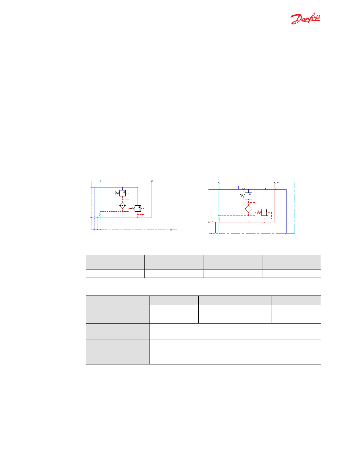
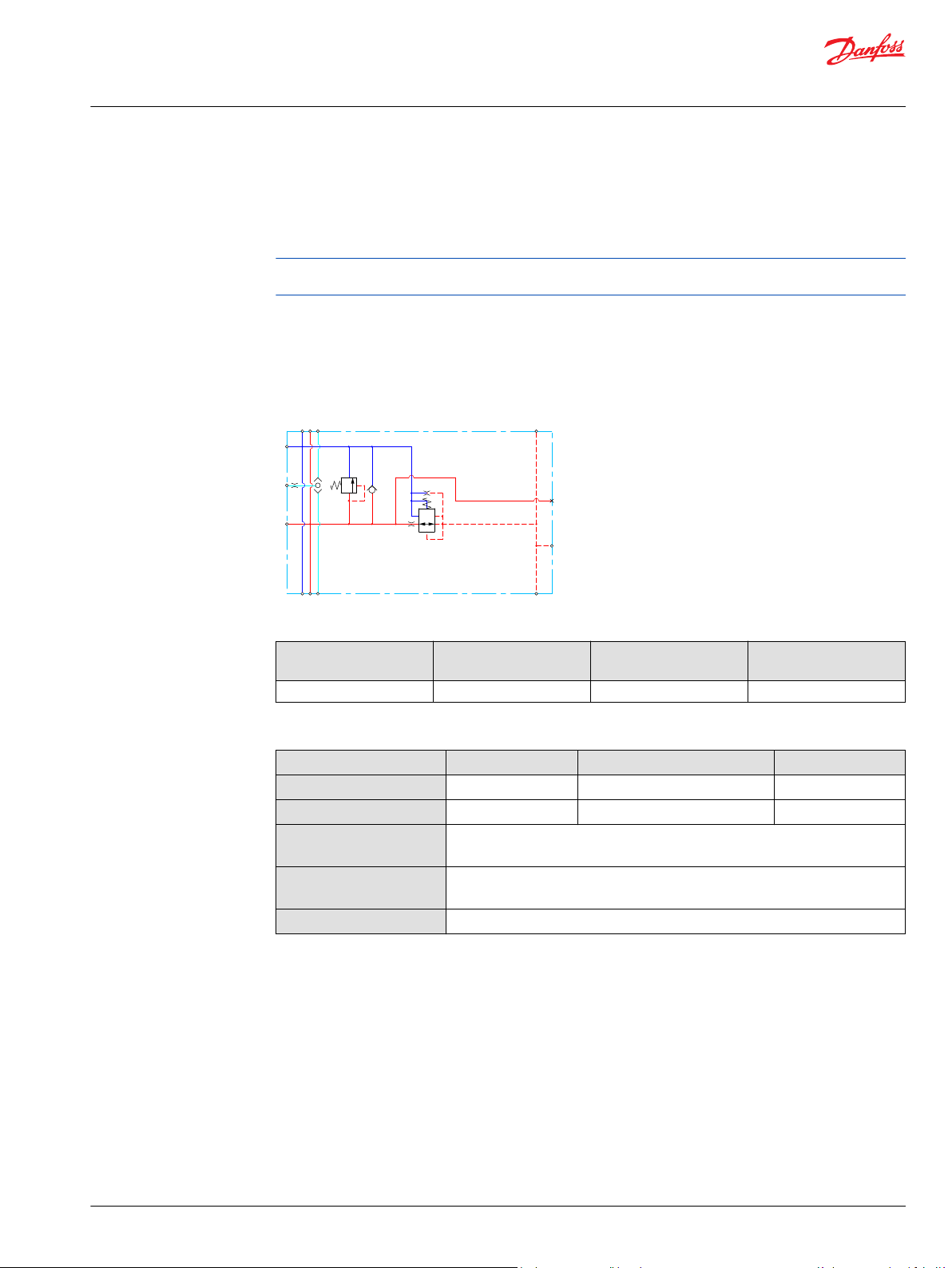
Open Center PVP
The basic Open Center PVP inlet module is intended for use with fixed displacement pumps in
applications, where a valve group with mechanically controlled work sections is desired, or where the
pilot pressure to the valve group is supplied externally.
The Open Center PVP features:
Integrated LS pressure relief valve
•
Threaded ports for P/T/LS and M measuring gauge
•
Optional LS unloading valve, PVPX
•
Optional T0 facility and external T0 port
•
Models with T0 port have internal T0 connection closed by default.
•
All modules can be manually activated with the PVM actuation.
Open center PVP schematic
Open center PVP with T0
Technical specification for PVP
Max. P-port continuous Max. P-port intermittent Max. T-port static/
dynamic
350 [5076 psi] 400 bar [5800 psi] 25/40 bar [365/580 psi] 140 l/min [37 US gal/min]
Max. rated flow
Technical specification
Parameter Minimum Recommended range Maximum
Fluid temperature
Fluid viscosity
Fluid cleanliness
(mechanical activation)
Fluid cleanliness
(PVE activation)
Operating temperature
-30°C [-22°F] 30 to 60°C [86 to 140°F] 90° [194°F]
4 mm2/s [39 SUS] 12 to 75 mm2/s [65 to 347 SUS] 460 mm2/s [2128 SUS]
23/19/16 (according to ISO 4406)
18/16/13 (according to ISO 4406)
Ambient: -30 to 60°C [-22 to 140°F]
10 | © Danfoss | July 2021 BC152986484323en-001104
[l/min]
[US gal/min]
200
150
100
50
20
40
60
80
100
120
140
Q
300
250
P
P
2000
1000
0
0
0
204 8
28
24
32
36
12
16
0
3000
4000
[psi] Q(bar)
(l/min)
[US gal/min]
20
20
40
60 80
100
120
140
16
12
8
4
160
80
0
0
0
240
[psi] (bar)
4
8
12
16
20
24
28
32
36
0
Technical Information
PVG 16 Proportional Valve Group
PVP Inlet Modules
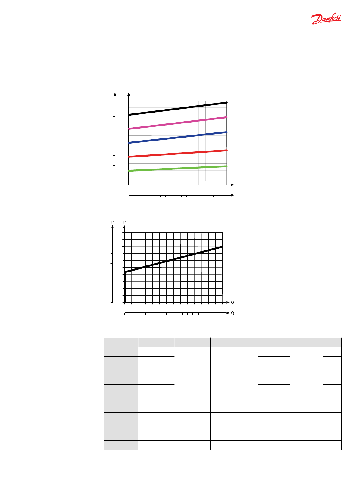
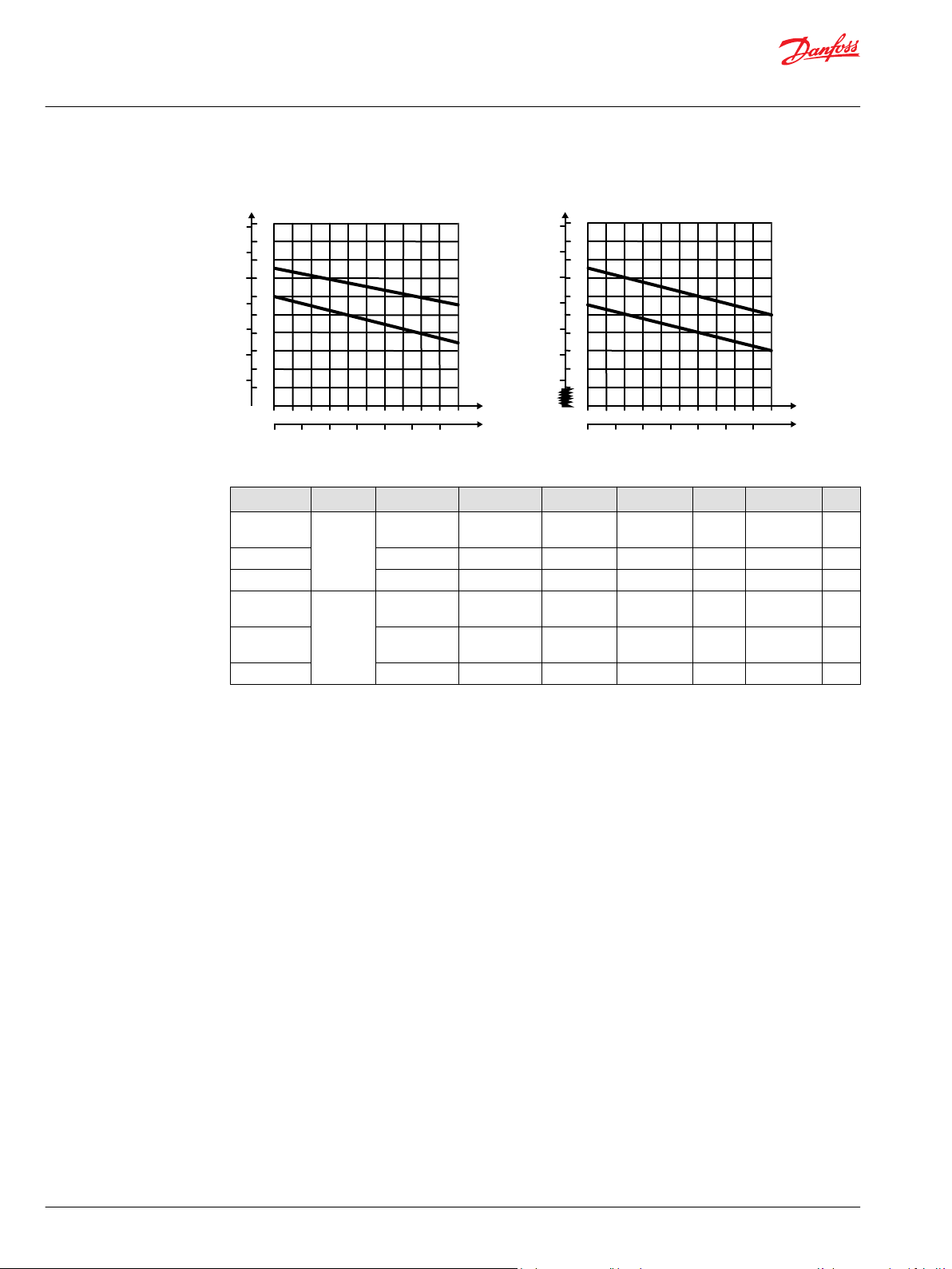
Theoretical Performance Graphs
Integrated LS pressure relief valve characteristics
Neutral by-pass pressure drop characteristics
Part numbers for Open Center PVP
Part number P-port T-port LS-, M-port (LS1**) T0-port Mounting PVPX
157B5000
157B5100
157B5102
157B5200
157B5300
11008852
11030545
11053974
11151852
157B5908
157B5921
G1/2”
G3/4” – -
G3/4” G1/4”
G3/4” - Yes
7/8-14 UNF
1-1/16 UN - -
1
G1/2 G3/4 G1/4 (G1/8) - M8 -
1 1/16-12 UNF 1/2-20 UNF
G3/4 G3/4 G1/4 (G1/4) G1/4 M8 -
G3/4 G3/4 G1/4 (G1/4) G1/4 M8 -
1 1/16-12 UNF 1 1/16-12 UNF 9/16-18 UNF 9/16-18 UNF M8 -
1 1/16-12 UNF 1 1/16-12 UNF 1/2-20 UNF - M8 -
JIS 1/2 JIS 3/4 JIS 1/4 - M8 -
-
M8
5/16-18 UNC
*
–
-
©
Danfoss | July 2021 BC152986484323en-001104 | 11
Technical Information
PVG 16 Proportional Valve Group
PVP Inlet Modules
Part numbers for Open Center PVP (continued)
Part number P-port T-port LS-, M-port (LS1**) T0-port Mounting PVPX
157B5925
157B5945
157B5990
**
LS1 is an extra LS-port.
*
For more information see PVPX Electrical LS Pressure Unloading Valve on page 33.
1
Dampened LS response
2
No relief valve
JIS 3/4 JIS 3/4 JIS 1/4 - M8 -
G1/2 G3/4 G1/4 (G1/8) - M8 -
2
1 1/16-12 UNF 1 1/16-12 UNF - - M8 -
*
12 | © Danfoss | July 2021 BC152986484323en-001104
LS
T
P
M
Pp
LS
T
P
M T0
Pp
Technical Information
PVG 16 Proportional Valve Group
PVP Inlet Modules
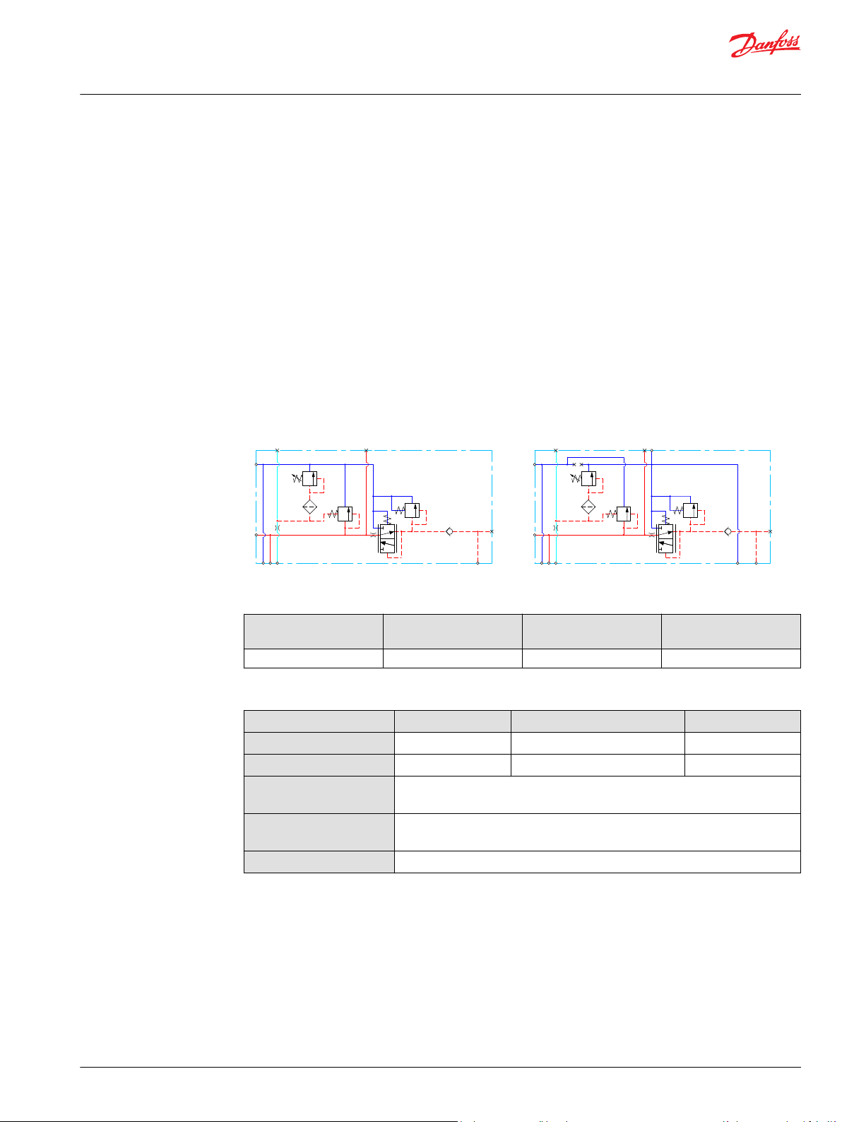
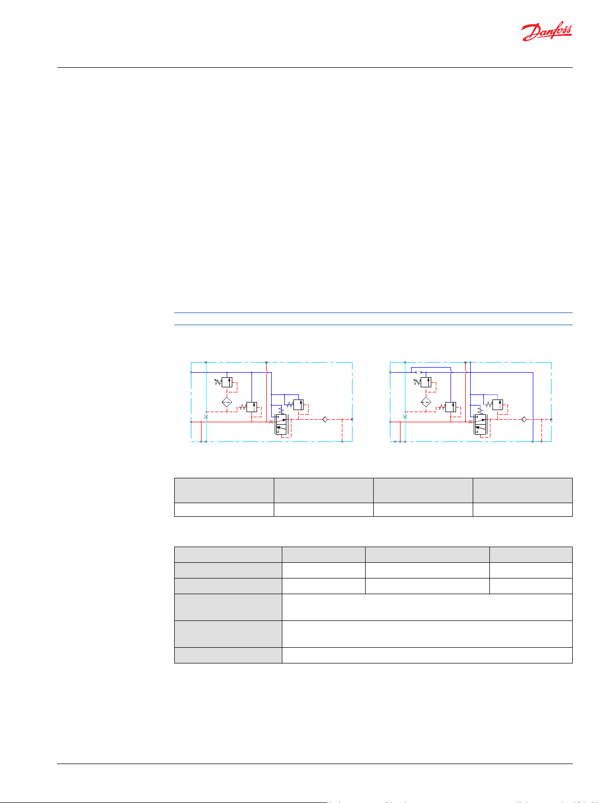
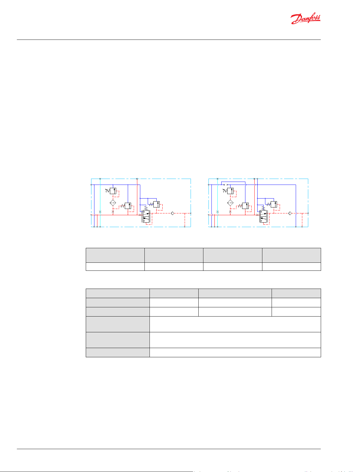
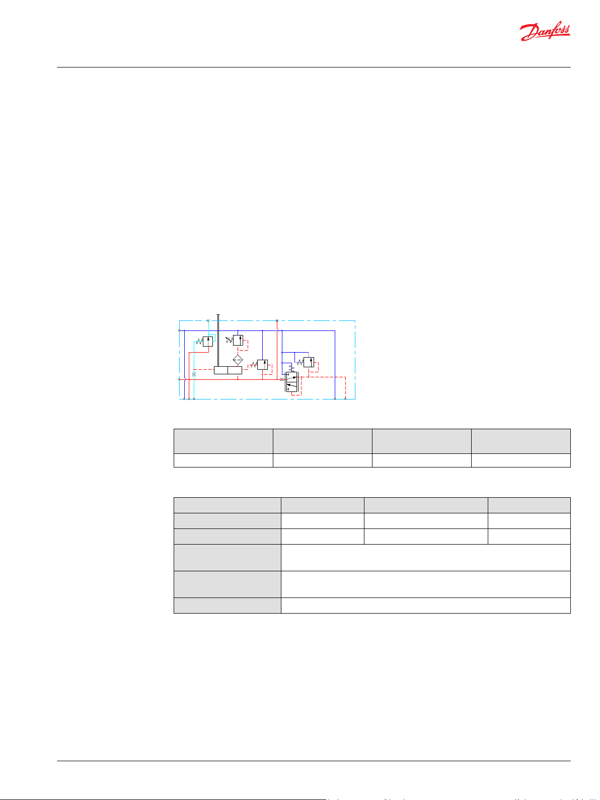
Open Center PVP with PPRV
The Open Center PVP inlet with integrated pilot pressure reduction valve (PPRV) is intended for use with
fixed displacement pumps in applications, where a valve group with electro-hydraulically or hydraulically
controlled work sections is desired (PVE or PVH/PVHC).
The Open Center PVP with PPRV features:
Integrated LS pressure relief valve
•
Threaded ports for P/T/LS and M measuring gauge
•
Integrated pilot pressure reducing valve (PPRV) for PVE or PVH/PVHC
•
Optional external pilot pressure port (Pp)
•
Optional LS unloading valve, PVPX
•
Models with T0 port have internal T0 connection closed by default.
•
All modules can be manually activated with the PVM actuation.
Open center PVP with PPRV schematic
Open center PVP with PPRV and T0
Technical specification for PVP
Max. P-port continuous Max. P-port intermittent Max. T-port static/
dynamic
350 [5076 psi] 400 bar [5800 psi] 25/40 bar [365/580 psi] 140 l/min [37 US gal/min]
Max. rated flow
Technical specification
Parameter Minimum Recommended range Maximum
Fluid temperature
Fluid viscosity
Fluid cleanliness
(mechanical activation)
Fluid cleanliness
(PVE activation)
Operating temperature
-30°C [-22°F] 30 to 60°C [86 to 140°F] 90° [194°F]
4 mm2/s [39 SUS] 12 to 75 mm2/s [65 to 347 SUS] 460 mm2/s [2128 SUS]
23/19/16 (according to ISO 4406)
18/16/13 (according to ISO 4406)
Ambient: -30 to 60°C [-22 to 140°F]
©
Danfoss | July 2021 BC152986484323en-001104 | 13
[l/min]
[US gal/min]
200
150
100
50
20
40
60
80
100
120
140
Q
300
250
P
P
2000
1000
0
0
0
204 8
28
24
32
36
12
16
0
3000
4000
[psi] Q(bar)
(l/min)
[US gal/min]
20
20
40
60 80
100
120
140
16
12
8
4
160
80
0
0
0
240
[psi] (bar)
4
8
12
16
20
24
28
32
36
0
1 2 3 4 5
[l/min]
[US gal/min]
0.2
0.4 0.6 0.8
1.0
1.2
20
16
12
8
4
0
Q
P
240
160
80
0
0
[psi] [bar]
0
Q
Max.
Min.
280
200
120
40
2
18
14
10
6
1 2 3 4 5
[l/min]
[US gal/min]
0.2
0.4
0.6 0.8 1.0 1.2
30
26
22
18
14
0
Q
P
440
360
280
0
0
[psi] [bar]
0
Q
Max.
Min.
480
400
320
240
12
28
24
20
16
PVE PVH/PVHC
Technical Information
PVG 16 Proportional Valve Group
PVP Inlet Modules
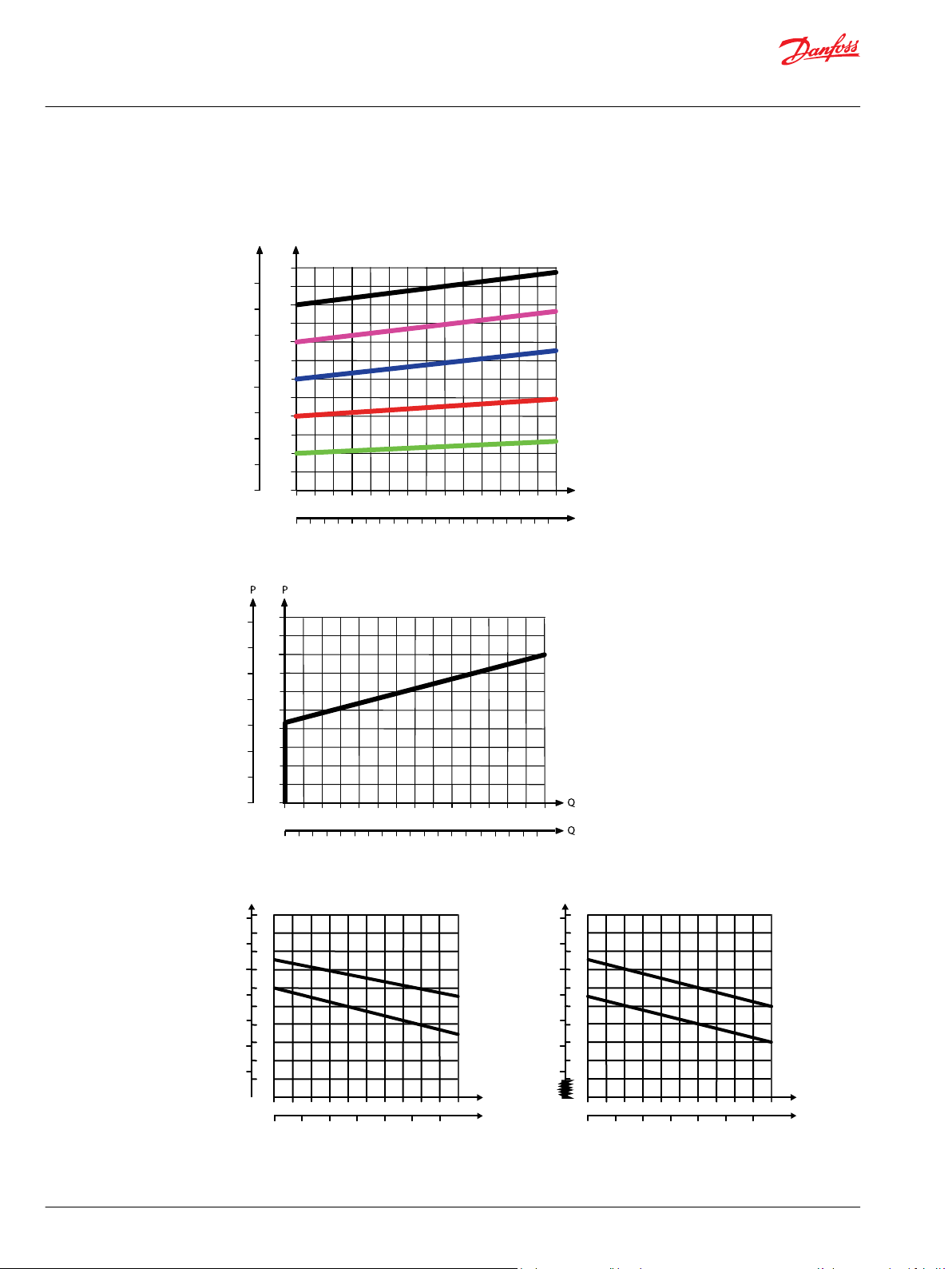
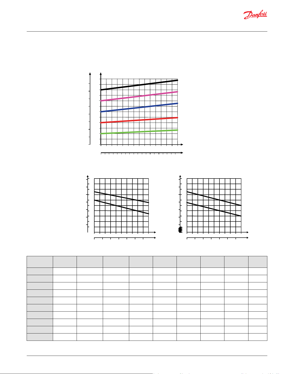
Theoretical Performance Graphs
Integrated LS pressure relief valve characteristics
Neutral by-pass pressure drop characteristics
Pilot pressure reduction valve characteristics
14 | © Danfoss | July 2021 BC152986484323en-001104
Technical Information
PVG 16 Proportional Valve Group
PVP Inlet Modules
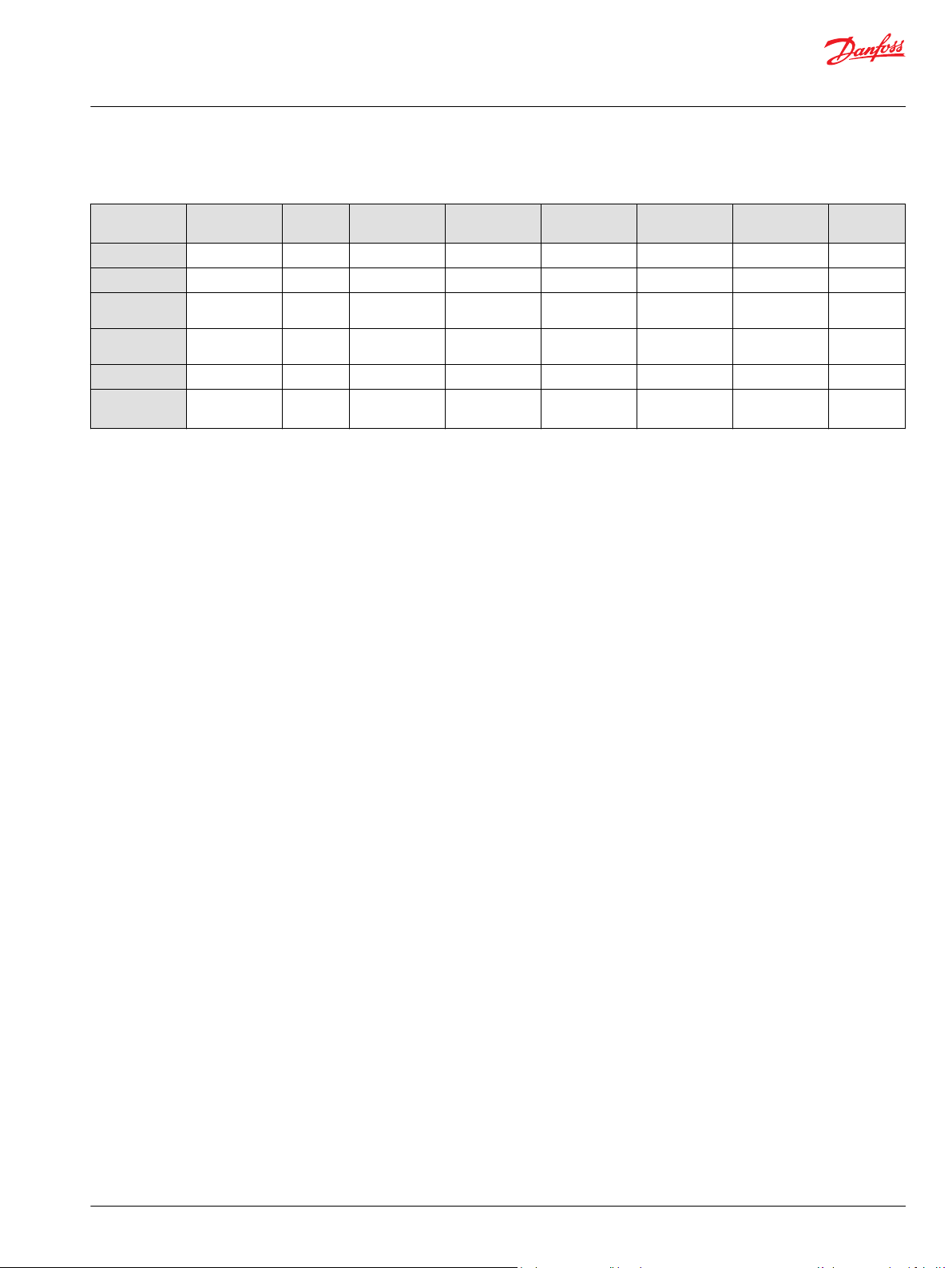
Part numbers for Open Center PVP with PPRV
Part number Actuation P-port T-port LS-port M-port Pp-port T0-port Mounting PVPX
157B5010
157B5012
157B5110
157B5112
157B5180
157B5190
157B5210
157B5212
157B5310
157B5312
157B5380
157B5390
11008850
11013317
11020964
11087590
11090453
11119429
11124965
11124966
11130941
11167773
11187356
11190123
11196947
11225941
157B5135
157B5904
157B5923
157B5926
157B5934
157B5943
157B5953
157B5954
157B5960
157B5966
157B5976
PVE G1/2” G3/4” G1/4” G1/4” - - M8 -
PVE G1/2” G3/4” G1/4” G1/4” - - M8 Yes
PVE G3/4” G3/4” G1/4” G1/4” - - M8 -
PVE G3/4” G3/4” G1/4” G1/4” - - M8 Yes
PVE G3/4” G3/4” G1/4” G1/4” G1/4” - M8 -
PVH/PVHC G3/4” G3/4” G1/4” G1/4” G1/4” - M8 -
PVE 7/8-14 UNF 1 1/16-12 UNF 1/2-20 UNF 1/2-20 UNF - - 5/16-18 UNC -
PVE 7/8-14 UNF 1 1/16-12 UNF 1/2-20 UNF 1/2-20 UNF - - 5/16-18 UNC Yes
PVE 1 1/16-12 UNF 1 1/16-12 UNF 1/2-20 UNF 1/2-20 UNF - - 5/16-18 UNC -
PVE 1 1/16-12 UNF 1 1/16-12 UNF 1/2-20 UNF 1/2-20 UNF - - 5/16-18 UNC Yes
PVE 1 1/16-12 UNF 1 1/16-12 UNF 9/16-18 UNF 9/16-18 UNF 9/16-18 UNF - 5/16-18 UNC -
PVH/PVHC 1 1/16-12 UNF 1 1/16-12 UNF 9/16-18 UNF 9/16-18 UNF 9/16-18 UNF - 5/16-18 UNC -
PVE G3/4 G3/4 G1/4 G1/4 - - M8 Yes
1
PVE G3/4 G3/4 G1/4 G1/4 G1/4 G1/4 M8 -
PVE 1 1/16-12 UNF 1 1/16-12 UNF 1/2-20 UNF 1/2-20 UNF - - M8 -
1
PVH/PVHC G3/4 G3/4 G1/4 G1/4 G1/4 - M8 -
PVE JIS 3/4 JIS 3/4 JIS 1/4 JIS 1/4 JIS 1/4 JIS 1/4 M8 -
2
PVE G3/4 G3/4 G1/4 G1/4 G1/4 - M8 -
PVH/PVHC G3/4 G3/4 G1/4 G1/4 G1/4 G1/4 M8 Yes
PVH/PVHC G3/4 G3/4 G1/4 G1/4 G1/4 G1/4 M8 -
2
PVE 1 1/16-12 UNF 1 1/16-12 UNF 9/16-18 UNF 9/16-18 UNF 9/16-18 UNF - 5/16-18 UNC -
PVH/PVHC 1 1/16-12 UNF 1 1/16-12 UNF 1/2-20 UNF 1/2-20 UNF - - 5/16-18 UNC Yes
4
PVE G1/2 G3/4 G1/4 G1/4 - - M8 Yes
PVH/PVHC G1/2 G3/4 G1/4 G1/4 - - M8 Yes
PVE G3/4 G3/4 G1/4 G1/4 - G1/4 M8 -
PVE 1 1/16-12 UNF 1 1/16-12 UNF 9/16-18 UNF 9/16-18 UNF 9/16-18 UNF 9/16-18
5/16-18 UNC -
UNF
3
PVE G3/4 G3/4 G1/4 G1/4 G1/4 G1/4 M8 -
2
PVE G3/4 G3/4 G1/4 G1/4 G1/4 - M8 -
PVE JIS 1/2 JIS 3/4 JIS 1/4 JIS 1/4 - - M8 -
PVE JIS 3/4 JIS 3/4 JIS 1/4 JIS 1/4 - - M8 -
PVE G3/4 G3/4 G1/4 G1/4 - - M8 -
2
PVH/PVHC G3/4 G3/4 G1/4 G1/4 G1/4 - M8 -
2
PVE G3/4 G3/4 G1/4 G1/4 - - M8 Yes
PVE G3/4 G3/4 G1/4 G1/4 G1/4 - M8 -
PVE 1 1/16-12 UNF 1 1/16-12 UNF 9/16-18 UNF 9/16-18 UNF - 9/16-18
5/16-18 UNF -
UNF
2
PVE G3/4 G3/4 G1/4 G1/4 - - M8 Yes
PVE G3/4 G3/4 G1/4 G1/4 - - M8 Yes
*
©
Danfoss | July 2021 BC152986484323en-001104 | 15

Technical Information
PVG 16 Proportional Valve Group
PVP Inlet Modules
Part numbers for Open Center PVP with PPRV (continued)
Part number Actuation P-port T-port LS-port M-port Pp-port T0-port Mounting PVPX
1,4
157B5977
11101194
*
For more information please see the topic PVPX Electrical LS Pressure Unloading Valve.
1
Dampened LS response
2
Pressure adjustment spool with check valve
3
Internal T0 connection
4
Low flow pressure adjustment spool
PVE G3/4 G3/4 G1/4 G1/4 - - M8 -
PVE M22 x 1.5 M22 x 1.5 M12 x 1.5 M10 x 1 - M16 x 1.5 M8 -
All modules can be manually activated with the PVM. For more information please see PVM Manual
Actuation on page 71.
*
16 | © Danfoss | July 2021 BC152986484323en-001104
LS
P
Pp
M
HPCO
LS
P
Pp
T0
M
HPCO
Technical Information
PVG 16 Proportional Valve Group
PVP Inlet Modules
Open center PVP with HPCO and PVE PPRV
The Open Center PVP inlet with integrated High Pressure Carry Over (HPCO) functionality is intended for
use with fixed displacement pumps in applications where one pump supply for multiple hydraulic
subsystems is desired.
The integrated HPCO functionality guides the excess flow of the PVG 16 valve group to the external
hydraulic subsystem(s), giving priority to the PVG 16 work functions.
The Open Center PVP with HPCO and PVE PPRV features:
Integrated LS pressure relief valve
•
Threaded ports for P/T/LS/HPCO and M measuring gauge
•
Integrated pilot pressure reducing valve (PPRV) for PVE
•
Optional T0 facility and external T0 port
•
Optional external pilot pressure port (Pp)
•
Optional LS unloading valve, PVPX
•
Models with T0 port have internal T0 connection closed by default.
•
Only applicable with PVST end plates with separate T-port due to blocked T-lines for HPCO functionality.
Open Center PVP with HPCO, PVE PPRV schematic
Open center PVP with HPCO, PPRV, and T0
Technical specification for PVP
Max. P-port continuous Max. P-port intermittent Max. T-port static/
dynamic
350 [5076 psi] 400 bar [5800 psi] 25/40 bar [365/580 psi] 140 l/min [37 US gal/min]
Max. rated flow
Technical specification
Parameter Minimum Recommended range Maximum
Fluid temperature
Fluid viscosity
Fluid cleanliness
(mechanical activation)
Fluid cleanliness
(PVE activation)
Operating temperature
-30°C [-22°F] 30 to 60°C [86 to 140°F] 90° [194°F]
4 mm2/s [39 SUS] 12 to 75 mm2/s [65 to 347 SUS] 460 mm2/s [2128 SUS]
23/19/16 (according to ISO 4406)
18/16/13 (according to ISO 4406)
Ambient: -30 to 60°C [-22 to 140°F]
©
Danfoss | July 2021 BC152986484323en-001104 | 17

[l/min]
[US gal/min]
200
150
100
50
20
40
60
80
100
120
140
Q
300
250
P
P
2000
1000
0
0
0
204 8
28
24
32
36
12
16
0
3000
4000
[psi] Q(bar)
(l/min)
[US gal/min]
20
20
40
60 80
100
120
140
16
12
8
4
160
80
0
0
0
240
[psi] (bar)
4
8
12
16
20
24
28
32
36
0
1 2 3 4 5
[l/min]
[US gal/min]
0.2
0.4 0.6 0.8
1.0
1.2
20
16
12
8
4
0
Q
P
240
160
80
0
0
[psi] [bar]
0
Q
Max.
Min.
280
200
120
40
2
18
14
10
6
1 2 3 4 5
[l/min]
[US gal/min]
0.2
0.4
0.6 0.8 1.0 1.2
30
26
22
18
14
0
Q
P
440
360
280
0
0
[psi] [bar]
0
Q
Max.
Min.
480
400
320
240
12
28
24
20
16
PVE PVH/PVHC
Technical Information
PVG 16 Proportional Valve Group
PVP Inlet Modules
Theoretical Performance Graphs
Integrated LS pressure relief valve characteristics
Neutral by-pass pressure drop characteristics
Pilot pressure reduction valve characteristics
18 | © Danfoss | July 2021 BC152986484323en-001104
Technical Information
PVG 16 Proportional Valve Group
PVP Inlet Modules
Part numbers for OC PVP (HPCO and PPRV)
Part number P-port HPCO-
157B5140
157B5142
157B5340
157B5342
157B5961
11101195
*
For more information please see the topic PVPX Electrical LS Pressure Unloading Valve.
G3/4” G3/4" G1/4” G1/4” G1/4” G1/4” M8 -
G3/4” G3/4" G1/4” G1/4” G1/4” – M8 Yes
1 1/16-12 UNF 1 1/16-12
1 1/16-12 UNF 1 1/16-12
M27x2 M27x2 M14x1.5 M14x1.5 – M14x1.5 M8 –
M22x1.5
M16x1.5 (P2)
port
UNF
UNF
M22x1.5 M12x1.5 M10x1 – M16x1.5 M8 –
LS-port M-port Pp-port T0-port Mounting PVPX
1/2-20 UNF 1/2-20 UNF 1/2-20 UNF 1/2-20 UNF 5/16-18 UNC -
1/2-20 UNF 1/2-20 UNF 1/2-20 UNF – 5/16-18 UNC Yes
*
©
Danfoss | July 2021 BC152986484323en-001104 | 19
LS
T
P
M
Technical Information
PVG 16 Proportional Valve Group
PVP Inlet Modules
Closed Center PVP
The basic Closed Center PVP inlet is intended for use with variable displacement pumps in applications
where a valve group with mechanically controlled work sections is desired, or where the pilot pressure to
the valve group is supplied externally.
The Closed Center PVP features:
Integrated LS pressure relief valve
•
Threaded ports for P/T/LS and M measuring gauge
•
Optional LS unloading valve, PVPX
•
Optional T0 facility and external T0 port
•
Models with T0 port have internal T0 connection closed by default.
•
Closed center PVP schematic
Technical specification for PVP
Max. P-port continuous Max. P-port intermittent Max. T-port static/
dynamic
350 [5076 psi] 400 bar [5800 psi] 25/40 bar [365/580 psi] 140 l/min [37 US gal/min]
Max. rated flow
Technical specification
Parameter Minimum Recommended range Maximum
Fluid temperature
Fluid viscosity
Fluid cleanliness
(mechanical activation)
Fluid cleanliness
(PVE activation)
Operating temperature
-30°C [-22°F] 30 to 60°C [86 to 140°F] 90° [194°F]
4 mm2/s [39 SUS] 12 to 75 mm2/s [65 to 347 SUS] 460 mm2/s [2128 SUS]
23/19/16 (according to ISO 4406)
18/16/13 (according to ISO 4406)
Ambient: -30 to 60°C [-22 to 140°F]
20 | © Danfoss | July 2021 BC152986484323en-001104
[l/min]
[US gal/min]
200
150
100
50
20
40
60
80
100
120
140
Q
300
250
P
P
2000
1000
0
0
0
204 8
28
24
32
36
12
16
0
3000
4000
[psi] Q(bar)
Technical Information
PVG 16 Proportional Valve Group
PVP Inlet Modules
Theoretical Performance Graphs
Integrated LS pressure relief valve characteristics
Part numbers for Closed Center PVP
Part
number
P-port T-port LS-port
(LS1**)
M-port T0-port Mounting PVPX
11030683 G3/4 G3/4 G1/4 (G1/4) G1/4 G1/4 M8 157B5001 G1/2 G3/4 G1/4 G1/4 - M8 157B5101 G3/4 G3/4 G1/4 G1/4 - M8 157B5103 G3/4 G3/4 G1/4 G1/4 - M8 Yes
157B5201 7/8-14 UNF 1 1/16-12
1/2-20 UNF 1/2-20 UNF -- 5/16-18 UNC -
UNF
157B5301 1 1/16-12
UNF
15B5907 1 1/16-12
UNF
1 1/16-12
UNF
1 1/16-12
UNF
1/2-20 UNF 1/2-20 UNF - 5/16-18 UNC -
1/2-20 UNF 1/2-20 UNF - M8 -
157B5922 JIS 1/2 JIS 3/4 JIS 1/4 JIS 1/4 - M8 157B5927 JIS 3/4 JIS 3/4 JIS 1/4 JIS 1/4 - M8 157B5946 G1/2 G3/4 G1/4 (G1/8) G1/4 - M8 -
**
LS1 is an extra LS-port
*
For more information see PVPX Electrical LS Pressure Unloading Valve on page 33
*
©
Danfoss | July 2021 BC152986484323en-001104 | 21
LS
T
P
M
Pp
LS
T
P
M
T0
Pp
Technical Information
PVG 16 Proportional Valve Group
PVP Inlet Modules
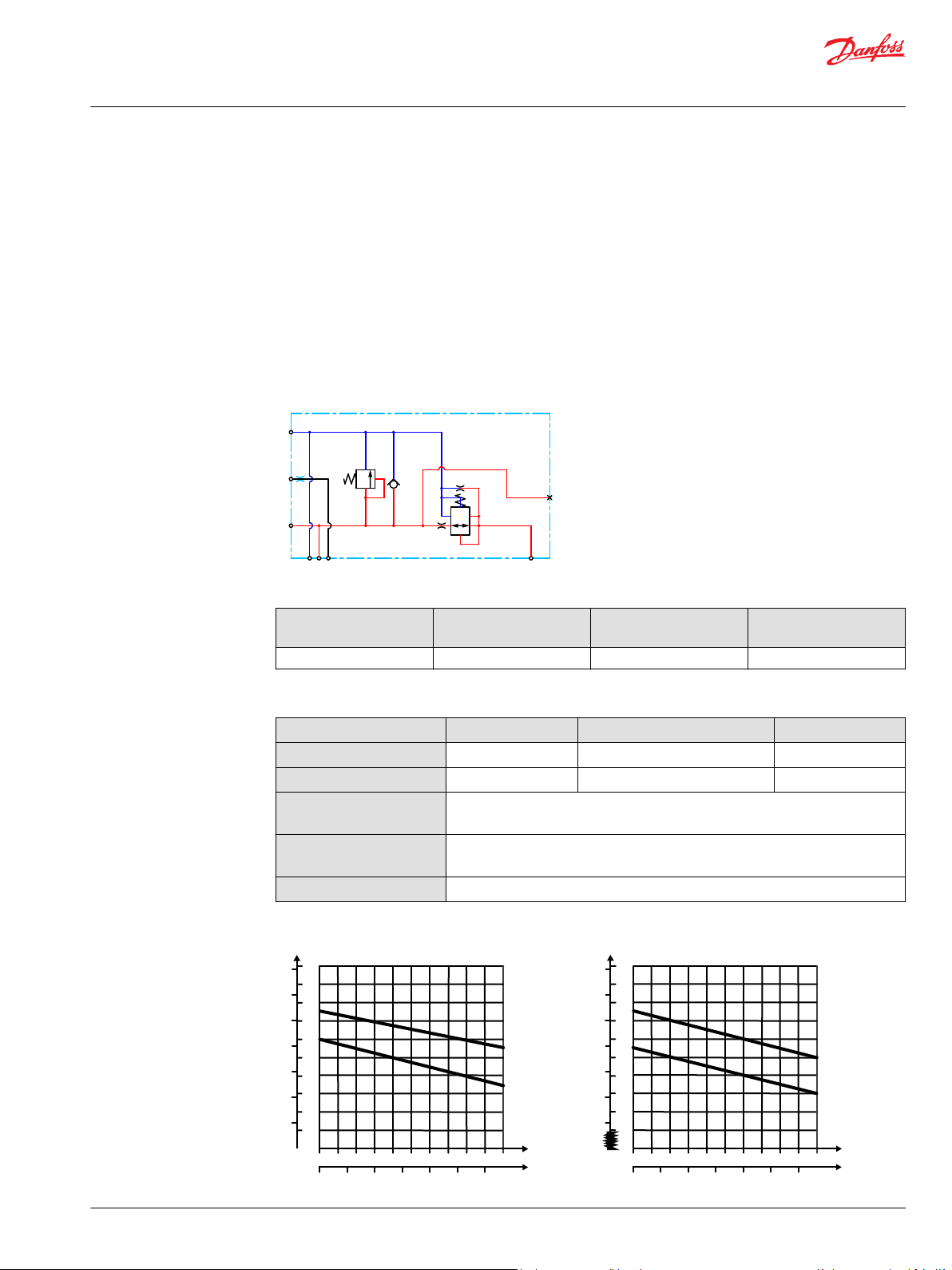
Closed Center PVP with PPRV
The Closed Center PVP inlet with integrated pilot pressure reduction valve (PPRV) is intended for use with
variable displacement pumps in applications where a valve group with electro-hydraulic or hydraulically
controlled work sections is desired.
The Closed Center PVP with PPRV features:
Integrated LS pressure relief valve
•
Threaded ports for P/T/LS and M measuring gauge
•
Integrated pilot pressure reducing valve (PPRV) for PVE or PVH/PVHC
•
Optional external pilot pressure port (Pp)
•
Optional LS unloading valve, PVPX
•
Models with T0 port have internal T0 connection closed by default.
•
Closed center PVP with PPRV schematic
Closed center PVP with PPRV and T0
Technical specification for PVP
Max. P-port continuous Max. P-port intermittent Max. T-port static/
dynamic
350 [5076 psi] 400 bar [5800 psi] 25/40 bar [365/580 psi] 140 l/min [37 US gal/min]
Max. rated flow
Technical specification
Parameter Minimum Recommended range Maximum
Fluid temperature
Fluid viscosity
Fluid cleanliness
(mechanical activation)
Fluid cleanliness
(PVE activation)
Operating temperature
-30°C [-22°F] 30 to 60°C [86 to 140°F] 90° [194°F]
4 mm2/s [39 SUS] 12 to 75 mm2/s [65 to 347 SUS] 460 mm2/s [2128 SUS]
23/19/16 (according to ISO 4406)
18/16/13 (according to ISO 4406)
Ambient: -30 to 60°C [-22 to 140°F]
22 | © Danfoss | July 2021 BC152986484323en-001104
[l/min]
[US gal/min]
200
150
100
50
20
40
60
80
100
120
140
Q
300
250
P
P
2000
1000
0
0
0
204 8
28
24
32
36
12
16
0
3000
4000
[psi] Q(bar)
1 2 3 4 5
[l/min]
[US gal/min]
0.2
0.4 0.6 0.8
1.0
1.2
20
16
12
8
4
0
Q
P
240
160
80
0
0
[psi] [bar]
0
Q
Max.
Min.
280
200
120
40
2
18
14
10
6
1 2 3 4 5
[l/min]
[US gal/min]
0.2
0.4
0.6 0.8 1.0 1.2
30
26
22
18
14
0
Q
P
440
360
280
0
0
[psi] [bar]
0
Q
Max.
Min.
480
400
320
240
12
28
24
20
16
PVE PVH/PVHC
Technical Information
PVG 16 Proportional Valve Group
PVP Inlet Modules
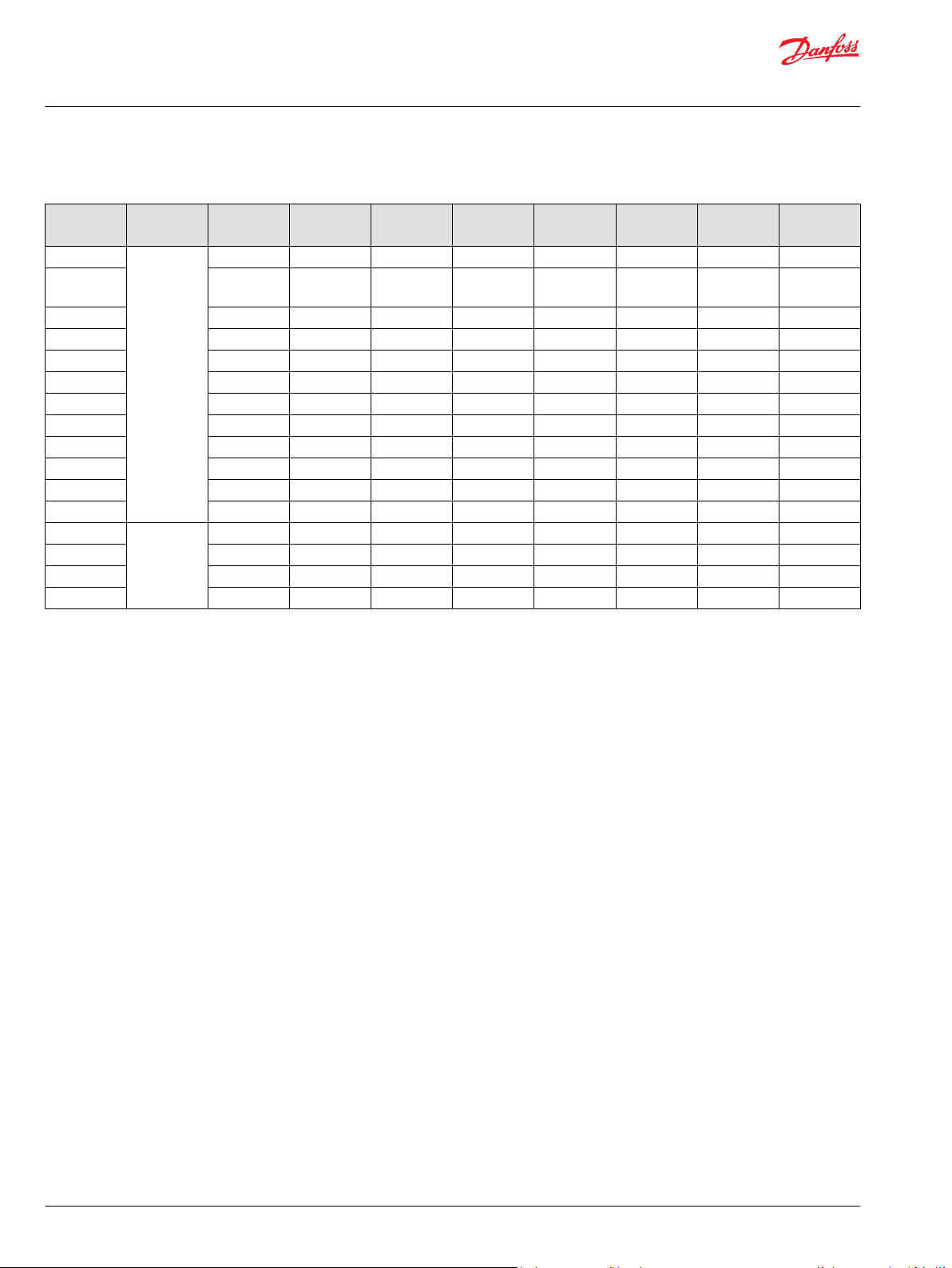
Theoretical Performance Graphs
Integrated LS pressure relief valve characteristics
Pilot pressure reduction valve characteristics
Part numbers for Closed Center PVP with PPRV
Part number Actuation P-port T-port LS-port
157B5011
157B5013
157B5111
157B5113
157B5181
157B5191
157B5211
157B5213
157B5311
157B5313
©
Danfoss | July 2021 BC152986484323en-001104 | 23
PVE G1/2” G3/4” G1/4” G1/4” - - M8 -
PVE G1/2” G3/4” G1/4” G1/4” - - M8 Yes
PVE G3/4” G3/4” G1/4” G1/4” - - M8 -
PVE G3/4” G3/4” G1/4” G1/4” - - M8 Yes
PVE G3/4” G3/4” G1/4” G1/4” G1/4” - M8 -
PVH/PVHC G3/4” G3/4” G1/4” G1/4” G1/4” - M8 -
PVE 7/8-14 UNF 1 1/16-12 UNF 1/2-20 UNF 1/2-20 UNF - - 5/16-18 UNC -
PVE 7/8-14 UNF 1 1/16-12 UNF 1/2-20 UNF 1/2-20 UNF - - 5/16-18 UNC Yes
PVE 1 1/16-12 UNF 1 1/16-12 UNF 1/2-20 UNF 1/2-20 UNF - - 5/16-18 UNC -
PVE 1 1/16-12 UNF 1 1/16-12 UNF 1/2-20 UNF 1/2-20 UNF - - 5/16-18 UNC Yes
**
(LS1
M-port Pp-port T0-port Mounting PVPX
*

Technical Information
PVG 16 Proportional Valve Group
PVP Inlet Modules
Part numbers for Closed Center PVP with PPRV (continued)
Part number Actuation P-port T-port LS-port
157B5381
157B5391
**
LS1 is an extra LS-port
*
For more information please see PVPX Electrical LS Pressure Unloading Valve on page 33
PVE 1 1/16-12 UNF 1 1/16-12 UNF 9/16-18 UNF 9/16-18 UNF 9/16-18 UNF - 5/16-18 UNC -
PVH/PVHC 1 1/16-12 UNF 1 1/16-12 UNF 9/16-18 UNF 9/16-18 UNF 9/16-18 UNF - 5/16-18 UNC
(LS1
**
All modules can be manually activated with the PVM actuation.
For more information, please see PVM Manual Actuation on page 71.
M-port Pp-port T0-port Mounting PVPX
*
24 | © Danfoss | July 2021 BC152986484323en-001104
T
LS
P
M
1 2 3 4 5
[l/min]
[US gal/min]
0.2
0.4 0.6 0.8
1.0
1.2
20
16
12
8
4
0
Q
P
240
160
80
0
0
[psi] [bar]
0
Q
Max.
Min.
280
200
120
40
2
18
14
10
6
1 2 3 4 5
[l/min]
[US gal/min]
0.2
0.4
0.6 0.8 1.0 1.2
30
26
22
18
14
0
Q
P
440
360
280
0
0
[psi] [bar]
0
Q
Max.
Min.
480
400
320
240
12
28
24
20
16
PVE PVH/PVHC
Technical Information
PVG 16 Proportional Valve Group
PVP Inlet Modules
Closed center PVPV with PPRV
The Closed Center PVPV inlet with integrated pilot pressure reduction valve (PPRV) is intended for use
with variable displacement pumps in applications where a valve group with electro-hydraulic or
hydraulically controlled work sections is desired.
The Closed Center PVPV with PPRV features:
Optional shock/anti-cavitation valve facility (PVLP)
•
Threaded ports for P/T/LS and M measuring gauge
•
Integrated pilot pressure reducing valve (PPRV) for PVE or PVH/PVHC
•
Models with T0 port have internal T0 connection closed by default.
•
Hydraulic schematic
©
Danfoss | July 2021 BC152986484323en-001104 | 25
Technical specification for PVP
Max. P-port continuous Max. P-port intermittent Max. T-port static/
350 [5076 psi] 400 bar [5800 psi] 25/40 bar [365/580 psi] 150 l/min [37 US gal/min]
Technical specification
Parameter Minimum Recommended range Maximum
Fluid temperature
Fluid viscosity
Fluid cleanliness
(mechanical activation)
Fluid cleanliness
(PVE activation)
Operating temperature
Pilot pressure reduction valve characteristics
dynamic
Max. rated flow
-30°C [-22°F] 30 to 60°C [86 to 140°F] 90° [194°F]
4 mm2/s [39 SUS] 12 to 75 mm2/s [65 to 347 SUS] 460 mm2/s [2128 SUS]
23/19/16 (according to ISO 4406)
18/16/13 (according to ISO 4406)
Ambient: -30 to 60°C [-22 to 140°F]
Technical Information
PVG 16 Proportional Valve Group
PVP Inlet Modules
Part numbers for Closed Center PVPV with PPRV
Part number Actuator P-port T-port (T2) LS-port M-port Pp-port
T0-port
(T02)
11012350
11003806 M27x2.0
11008854
1
2
M27x2.0 M33x2.0 M14x1.5 M14x1.5 - - M8 -
M27x2.0
(M14x1.5)
M14x1.5 M14x1.5 -
M14x1.5
(M14x1.5)
G1 G1 G1/4 G1/4 - - M8 Yes
11124107 1 5/16-12 1 1/16-12 9/16-18 9/16-18 - - M8 Yes
11196949 G1 G1 - - G1/4 - M8 Yes
157B5911 1 5/16-12 1 5/16-12 9/16-18 9/16-18 - - 5/16-18 -
PVE
157B5913 1 5/16-12 1 5/16-12 9/16-18 9/16-18 - - 5/16-18 Yes
157B5938 G1 G1 G1/4 G1/4 - - M8 157B5941 G1 G1 G1/4 G1/4 - - M8 Yes
157B5948
157B5973
3
4
G1 G1 G1/4 G1/4 - - M8 Yes
G1 G1 G1/4 G1/4 - - M8 Yes
157B5978 M27x2.0 M33x2.0 M14x1.5 M14x1.5 - - M8 11008856
11051803 1 5/16-12 1 5/16-12 9/16-18 9/16-18 - - 5/16-18 Yes
157B5916 1 5/16-12 1 5/16-12 9/16-18 9/16-18 - - 5/16-18 -
PVH/PVHC
G1 G1 G1/4 G1/4 - - M8 Yes
157B5963 1 1/16-12 1 1/16-12 7/16-20 - - 9/16-18 M8 -
1
No LS-orifice
2
Internal T0 connection
3
0.4 mm hole in the pilot reduction cone (standard 0.8 mm)
4
HPCO-facility
Mounting PVLP
M8 -
All modules can be manually activated with the PVM actuation.
26 | © Danfoss | July 2021 BC152986484323en-001104
T
LS
P
M
Pp
Technical Information
PVG 16 Proportional Valve Group
PVP Inlet Modules
Closed center PVPVM with PPRV
The Closed Center PVPVM mid-inlet module with integrated pilot pressure reduction valve (PPRV) is
intended for use with variable displacement pumps in applications where a valve group with electrohydraulic or hydraulically controlled work sections is desired.
Using a PVPVM module in a valve group requires a 180° degree rotation of the PVG work sections on one
side.
The Closed Center PVPVM with PPRV features:
Optional shock/anti-cavitation valve facility (PVLP)
•
Threaded ports for P/T/LS and M measuring gauge
•
Integrated pilot pressure reducing valve (PPRV) for PVE or PVH/PVHC
•
Hydraulic schematic
Technical specification for PVP
Max. P-port continuous Max. P-port intermittent Max. T-port static/
dynamic
350 [5076 psi] 400 bar [5800 psi] 25/40 bar [365/580 psi] 230 l/min [61 US gal/min]
Max. rated flow
Technical specification
Parameter Minimum Recommended range Maximum
Fluid temperature
Fluid viscosity
Fluid cleanliness
(mechanical activation)
Fluid cleanliness
(PVE activation)
Operating temperature
-30°C [-22°F] 30 to 60°C [86 to 140°F] 90° [194°F]
4 mm2/s [39 SUS] 12 to 75 mm2/s [65 to 347 SUS] 460 mm2/s [2128 SUS]
23/19/16 (according to ISO 4406)
18/16/13 (according to ISO 4406)
Ambient: -30 to 60°C [-22 to 140°F]
©
Danfoss | July 2021 BC152986484323en-001104 | 27
1 2 3 4 5
[l/min]
[US gal/min]
0.2
0.4 0.6 0.8
1.0
1.2
20
16
12
8
4
0
Q
P
240
160
80
0
0
[psi] [bar]
0
Q
Max.
Min.
280
200
120
40
2
18
14
10
6
1 2 3 4 5
[l/min]
[US gal/min]
0.2
0.4
0.6 0.8 1.0 1.2
30
26
22
18
14
0
Q
P
440
360
280
0
0
[psi] [bar]
0
Q
Max.
Min.
480
400
320
240
12
28
24
20
16
PVE PVH/PVHC
Technical Information
PVG 16 Proportional Valve Group
PVP Inlet Modules
Pilot pressure reduction valve characteristics
Part numbers for Closed Center PVPVM with PPRV
Part number Actuator P-port T-port LS-port M-port Pp-port Mounting PVLP
157B5914
157B5937 G1 G1 G1/4 G1/4 G1/4 M8 157B5940 G1 G1 G1/4 G1/4 G1/4 M8 Yes
11083156
157B5912 1 5/16-12
157B5986 G1 G1 G1/4 G1/4 G1/4 M8 Yes
PVE
PVH/PVHC
1 5/16-12
UNF
1 1/16-12
UNF
UNF
1 5/16-12
UNF
1 1/16-12
UNF
1 5/16-12
UNF
9/16-18 UNF 9/16-18 UNF G1/4 5/16-18 UNC Yes
9/16-18 UNF 9/16-18 UNF G1/4 5/16-18 UNC Yes
9/16-18 UNF 9/16-18 UNF G1/4 5/16-18 UNC -
All modules can be manually activated with the PVM actuation.
28 | © Danfoss | July 2021 BC152986484323en-001104
LS
T
P
M
OC
CC
Technical Information
PVG 16 Proportional Valve Group
PVP Inlet Modules
Open/Closed center PVP with PPRV
The Open Center/Closed Center PVP with integrated pilot pressure reduction valve (PPRV) is intended for
use with fixed or variable displacement pumps in applications where the application manufacturer does
not determine the pump type.
The modules allow an easy switch between Open Center and Closed Center configuration by means of an
external hexagon selector key. Variants also feature an LS boost functionality, increasing the LS pressure
to the pump LS regulator with a constant 6 bar, compensating for potential LS bleed-off and leakage.
The Open/closed center PVP with PPRV features:
Integrated OC/CC selector
•
Integrated LS pressure relief valve
•
Threaded ports for P/T/LS and M measuring gauge
•
Integrated pilot pressure reducing valve (PPRV) for PVE or PVH/PVHC
•
Optional LS boost functionality
•
Hydraulic schematic
Technical specification for PVP
Max. P-port continuous Max. P-port intermittent Max. T-port static/
dynamic
350 [5076 psi] 400 bar [5800 psi] 25/40 bar [365/580 psi] 140 l/min [37 US gal/min]
Max. rated flow
Technical specification
Parameter Minimum Recommended range Maximum
Fluid temperature
Fluid viscosity
Fluid cleanliness
(mechanical activation)
Fluid cleanliness
(PVE activation)
Operating temperature
-30°C [-22°F] 30 to 60°C [86 to 140°F] 90° [194°F]
4 mm2/s [39 SUS] 12 to 75 mm2/s [65 to 347 SUS] 460 mm2/s [2128 SUS]
23/19/16 (according to ISO 4406)
18/16/13 (according to ISO 4406)
Ambient: -30 to 60°C [-22 to 140°F]
©
Danfoss | July 2021 BC152986484323en-001104 | 29

[l/min]
[US gal/min]
200
150
100
50
20
40
60
80
100
120
140
Q
300
250
P
P
2000
1000
0
0
0
204 8
28
24
32
36
12
16
0
3000
4000
[psi] Q(bar)
(l/min)
[US gal/min]
20
20
40
60 80
100
120
140
16
12
8
4
160
80
0
0
0
240
[psi] (bar)
4
8
12
16
20
24
28
32
36
0
1 2 3 4 5
[l/min]
[US gal/min]
0.2
0.4 0.6 0.8
1.0
1.2
20
16
12
8
4
0
Q
P
240
160
80
0
0
[psi] [bar]
0
Q
Max.
Min.
280
200
120
40
2
18
14
10
6
1 2 3 4 5
[l/min]
[US gal/min]
0.2
0.4
0.6 0.8 1.0 1.2
30
26
22
18
14
0
Q
P
440
360
280
0
0
[psi] [bar]
0
Q
Max.
Min.
480
400
320
240
12
28
24
20
16
PVE PVH/PVHC
Technical Information
PVG 16 Proportional Valve Group
PVP Inlet Modules
Theoretical Performance Graphs
Integrated LS pressure relief valve characteristics
Neutral by-pass pressure drop characteristics
Pilot pressure reduction valve characteristics
30 | © Danfoss | July 2021 BC152986484323en-001104

Technical Information
PVG 16 Proportional Valve Group
PVP Inlet Modules
Part numbers for Open/Closed Center PVP with PPRV
Part number Actuation P-port T-port LS-port (LS1**) M-port T0-port Mounting LS Boost
11093273 PVE G3/4 G3/4 - G1/4 - M8 Yes
11119094 PVE G3/4 G3/4 - G1/4 - M8 11119095 PVE 1 1/16-12 UNF 1 1/16-12 UNF 1/2-20 UNF 1/2-20 UNF - M8 11131344 PVH/PVHC G3/4 G3/4 - G1/4 - M8 Yes
111686081PVE G3/4 G3/4 - G1/4 - M8 Yes
**
LS1 is an extra LS-port
1
Dampened LS response
All modules can be manually activated with the PVM actuation.
©
Danfoss | July 2021 BC152986484323en-001104 | 31
T
P
Technical Information
PVG 16 Proportional Valve Group
PVP Inlet Modules
Open/Closed center PVPM
The Open Center/Closed Center PVPM mid-inlet acts as a simple manifold and is intended for use with
fixed or variable displacement pumps. The PVPM features no logic other than a PVLP shock/anticavitation valve facility for pressure peak protection and anti-cavitation prevention.
The PVPM module must be configured together with an Open Center PVP module for fixed
displacement pumps and for variable displacement pumps can be configured together with a PVSI
start plate or a Closed Center PVP/PVPV module.
The Open center/closed center PVPM features:
Integrated shock/anti-cavitation valve facility (PVLP)
•
Threaded ports for P/T
•
Pilot pressure and T0 lines through module
•
Hydraulic schematic
Technical specification for PVP
Max. P-port continuous Max. P-port intermittent Max. T-port static/
dynamic
350 [5076 psi] 400 bar [5800 psi] 25/40 bar [365/580 psi] 230 l/min [61 US gal/min]
Max. rated flow
Technical specification
Parameter Minimum Recommended range Maximum
Fluid temperature
Fluid viscosity
Fluid cleanliness
(mechanical activation)
Fluid cleanliness
(PVE activation)
Operating temperature
-30°C [-22°F] 30 to 60°C [86 to 140°F] 90° [194°F]
4 mm2/s [39 SUS] 12 to 75 mm2/s [65 to 347 SUS] 460 mm2/s [2128 SUS]
23/19/16 (according to ISO 4406)
18/16/13 (according to ISO 4406)
Ambient: -30 to 60°C [-22 to 140°F]
Part numbers for Open Center/Closed Center PVPM
Part number P-, T-port Mounting PVLP
11093682
11093684
1 5/16-12 UN 5/16-18 UNC Yes
G1” M8 Yes
32 | © Danfoss | July 2021 BC152986484323en-001104
P
T
MLS
Technical Information
PVG 16 Proportional Valve Group
PVP Inlet Module Accessories
The generic PVP inlet module accessory platform includes the PVPX Electrical LS pressure unloading
valve, External pilot pressure adapters PVPC with or without check valve for all Open Center PVP with
PPRV.
PVPX Electrical LS Pressure Unloading Valve on page 33
•
PVPC without Check Valve on page 36
•
PVPC with Check Valve on page 38
•
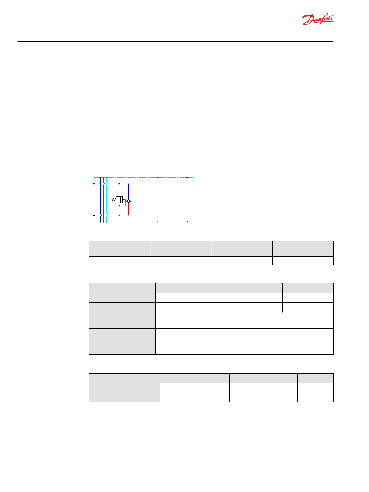
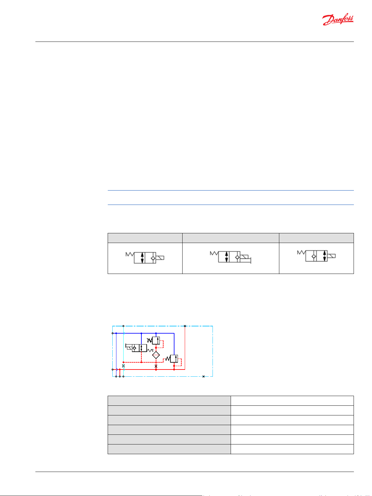
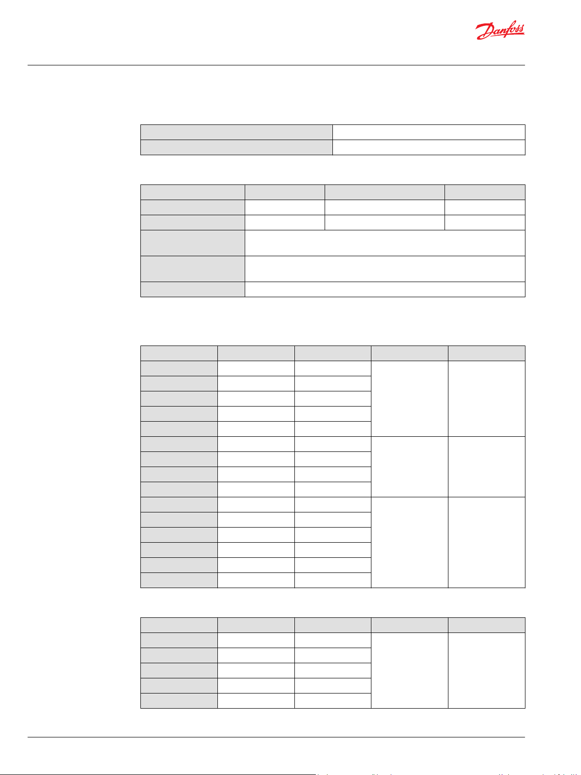
PVPX Electrical LS Pressure Unloading Valve
The electrical LS pressure unloading valve is an accessory available for PVP inlet modules with PVPX
facility. The PVPX consist of a solenoid valve and a magnetic coil package, allowing the operator to relieve
the LS pressure to tank electrically.
Configuration variants also feature a Manual Override functionality to activate the PVPX manually:
Normally Open (NO),
•
Normally Open with Manual Override (NOMO)
•
There are two types of NOMO-configurations - PUSH, and PUSH & TURN. With the TURN function you can
keep the override function until you unlock it again.
Normally Closed (NC)
•
Configuration variants
Normally Open (NO) Normally Open with MOR (NOMO) Normally Closed (NC)
Relieving the LS pressure to tank results in a reduced system pressure level, which is determined by:
the sum of the tank and neutral by-pass pressure drop in a Open Center PVP configuration
•
the sum of the tank and standby-pressure in a Closed Center PVP configuration
•
PVPX with NOMO schematic
PVPX technical data
Voltage supply
Resistance @ 12 V
Resistance @ 24 V
Power consumption
Maximum LS response time
Max. pressure drop @ 0.1 l/min [2.6 US gal/min]
DC
DC
12/24 VDC ± 10%
7.2 Ω ± 7%
28.2 Ω ± 7%
20 W
300 ms
2 bar [30 psi]
©
Danfoss | July 2021 BC152986484323en-001104 | 33
Technical Information
PVG 16 Proportional Valve Group
PVP Inlet Module Accessories
PVPX technical data (continued)
Max. coil surface temperature
Thread size
Technical specification
Parameter Minimum Recommended range Maximum
Fluid temperature
Fluid viscosity
Fluid cleanliness
(mechanical activation)
Fluid cleanliness
(PVE activation)
Operating temperature
Part numbers for PVPX
155°C [311°F]
3/4-16 UNF
-30°C [-22°F] 30 to 60°C [86 to 140°F] 90° [194°F]
4 mm2/s [39 SUS] 12 to 75 mm2/s [65 to 347 SUS] 460 mm2/s [2128 SUS]
23/19/16 (according to ISO 4406)
18/16/13 (according to ISO 4406)
Ambient: -30 to 60°C [-22 to 140°F]
Part numbers for PVPX, NO and NC configuration
Part number Configuration Voltage Supply Connector IP Rating
157B4236
157B4238
157B4246
157B4248
157B4976
157B4981
157B4982
157B4983
157B4984
11180766
11180767
11180768
11180769
11225108
11225109
NO 12 V
NO 24 V
NC 12 V
NC 24 V
NC 26 V
NO 12 V
NO 24 V
NC 12 V
NC 24 V
NO 12 V
NO 24 V
NC 12 V
NC 24 V
NO 26 V
NC 26 V
DC
DC
DC
DC
DC
DC
DC
DC
DC
DC
DC
DC
DC
DC
DC
1x2 DIN IP 65
1x2 AMP IP 66
1x2 DEUTSCH IP 67
Part numbers for PVPX, NOMO configuration
Part number Manual Override Voltage Supply Connector IP Rating
157B4256
157B4257
157B4258
157B4259
157B4260
PUSH 12 V
PUSH & TURN 12 V
PUSH 24 V
PUSH & TURN 24 V
PUSH 26 V
DC
DC
DC
DC
DC
1x2 DIN IP 65
34 | © Danfoss | July 2021 BC152986484323en-001104
Technical Information
PVG 16 Proportional Valve Group
PVP Inlet Module Accessories
Part numbers for PVPX, NOMO configuration (continued)
Part number Manual Override Voltage Supply Connector IP Rating
157B4985
157B4986
11193839
11193836
11225111
11225110
Part number for plug in PVPX port
Part number Description
157B5601 Plug
PUSH 12 V
PUSH 24 V
PUSH 12 V
PUSH 24 V
PUSH
PUSH & TURN
26 V
DC
DC
DC
DC
DC
1x2 AMP IP 66
1x2 DEUTSCH IP 67
©
Danfoss | July 2021 BC152986484323en-001104 | 35

Technical Information
PVG 16 Proportional Valve Group
PVP Inlet Module Accessories
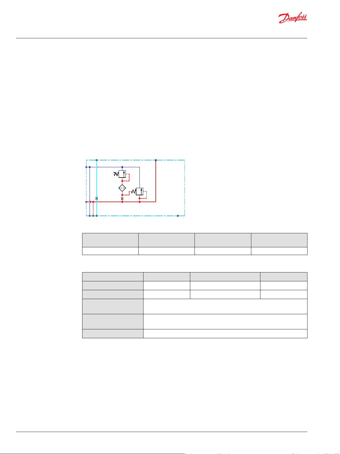
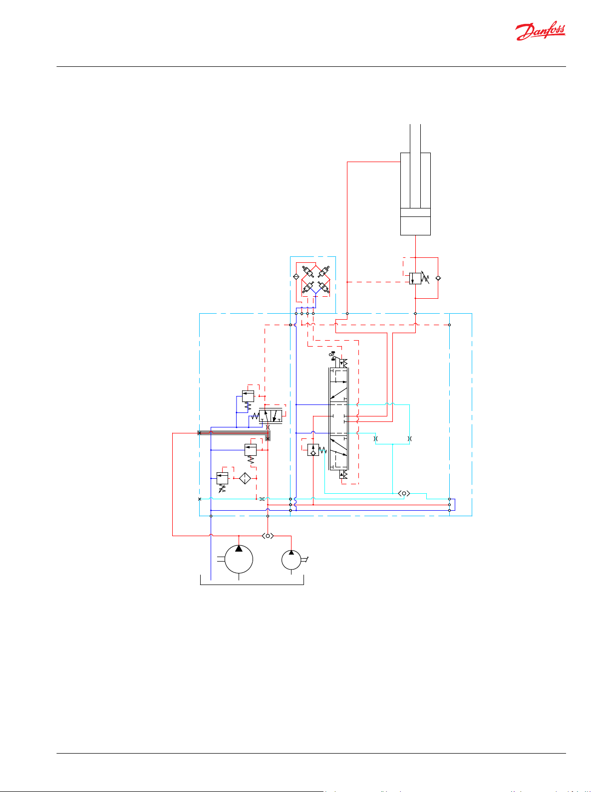
PVPC without Check Valve
The PVPC external pilot pressure adapter without check valve is an accessory in the M-port available for
PVP inlet modules with integrated pilot pressure reduction valve (PPRV).
The PVPC without check valve cuts off the integrated PPRV to the PVE or PVH/PVHC in the valve group
and enables an external pilot pressure supply through the PVPC adapter.
PVPC without Check Valve
One application example for the PVPC without check valve is where it is a wanted feature to supply the
valve group with oil from a manually operated emergency pump without directing oil flow to the PPRV.
When the main pump is running in its normal operation mode, the oil is directed through the PVPC
adapter via the PPRV to the PVE electrical actuators.
When the main pump flow fails, the external shuttle valve ensures that the oil flow from the manually
operated emergency pump is used to pilot open the over-center valve and lower the load. The load is
only possible to lower when using the mechanical operating lever of the PVG work sections.
Part numbers for Open Center/Closed Center PVPM
Part number 157B5400
Thread G1/2”
36 | © Danfoss | July 2021 BC152986484323en-001104
LS
T
P
M
A
B
Technical Information
PVG 16 Proportional Valve Group
PVP Inlet Module Accessories
Hydraulic diagram for PVPC without check valve
©
Danfoss | July 2021 BC152986484323en-001104 | 37

Technical Information
PVG 16 Proportional Valve Group
PVP Inlet Module Accessories
PVPC with Check Valve
The PVPC external pilot pressure adapter with check valve is an accessory in the M-port available for PVP
inlet modules with integrated pilot pressure reduction valve (PPRV).
The PVPC with check valve enables an external pilot pressure supply through the PVPC adapter and the
PPRV, while also allowing the main pump to supply the PPRV through the P-gallery as a standard Open
Center PVP with PPRV.
PVPC with Check Valve
One application example for the PVPC with check valve is where it is a wanted feature to operate the
valve group by means of the PVE electrical actuators without pump flow.
When the external solenoid valve is opened, oil from the pressure side of the cylinder is fed via the PVPC
through the PPRV to act as the pilot supply for the PVE electrical actuators. This means that it is possible
to lower a load by means of the PVE electrical actuators without starting the pump.
The built-in check valve prevents the oil from flowing via the pressure adjustment spool to tank. With the
pump functioning normally the external solenoid valve is closed to ensure that the load is not lowered
due to the pilot supply oil flow requirement of approximately 1 l/min [0.25 US gal/min].
With a Closed Center PVP the external pilot oil supply can be connected to the pressure gauge
connection without the use of a PVPC plug.
Part numbers for Open Center/Closed Center PVPM
Part number 157B5600 157B5700
Thread G1/2” 1/2-20 UNF
38 | © Danfoss | July 2021 BC152986484323en-001104

LS
T
P
M
A
B
Technical Information
PVG 16 Proportional Valve Group
PVP Inlet Module Accessories
Hydraulic diagram for PVPC with check valve
©
Danfoss | July 2021 BC152986484323en-001104 | 39

114 [4.49]
109 [4.29]
110 [4.33]
20 [0.79]
40 [1.57]
P
P
Technical Information
PVG 16 Proportional Valve Group
PVB Basic Modules
The PVG 16 PVB basic modules, also referred to as work sections, are the interface between the PVG 16
proportional valve group and the work function such as a cylinder or a motor.
PVB Basic Module PVB 16 dimensions
Weight: 2,6 kg [5,7 lb]
Uncompensated PVB schematic symbol
Compensated PVB schematic symbol
The PVB basic module variants are based on a generic platform with a selection of additional features,
enabling you to tailor the PVB to suit the demands of any hydraulic system. The generic PVB basic
module platform includes the following main variants:
Compensated basic module; Compensated PVB on page 41
•
Compensated basic module with facilities for shock and anti-cavitation valves (PVLP/PVLA);
•
Compensated PVB with PVLP/PVLA on page 44
Compensated basic module with one common adjustable LS valve for port A and port B;
•
Compensated PVB with LS A/B on page 48
Uncompensated basic module with optional integrated load drop check valve; Uncompensated PVB
•
on page 52
Uncompensated basic module with facilities for shock valves (PVLP) and optional integrated load
•
drop check valve; Uncompensated PVB with PVLP on page 55
40 | © Danfoss | July 2021 BC152986484323en-001104

A
B
1
0
2
A
B
1
0
2
Technical Information
PVG 16 Proportional Valve Group
PVB Basic Modules
Compensated PVB
The compensated PVB is intended for controlling a work function where the function behavior in terms
of flow and pressures requires independence on the load pressure of other functions used
simultaneously.
The Compensated PVB features:
Integrated LS shuttle network
•
Integrated compensator
•
Compensated PVB schematic
Compensated PVB with T0
Technical specification for A/B-port
Max. continuous pressure Max. intermittent pressure Max. rated flow
350 bar [5067 psi] 420 bar [6090 psi] 60 l/min [15 US gal/min]
Technical specification
Parameter Minimum Recommended range Maximum
Fluid temperature
Fluid viscosity
Fluid cleanliness
(mechanical activation)
Fluid cleanliness
(PVE activation)
Operating temperature
-30°C [-22°F] 30 to 60°C [86 to 140°F] 90° [194°F]
4 mm2/s [39 SUS] 12 to 75 mm2/s [65 to 347 SUS] 460 mm2/s [2128 SUS]
23/19/16 (according to ISO 4406)
18/16/13 (according to ISO 4406)
Ambient: -30 to 60°C [-22 to 140°F]
©
Danfoss | July 2021 BC152986484323en-001104 | 41

B
P
5
10
15
20
25
30
35
40
45
50
55
60
65
[l/min]
[US gal/min]
[mm]
PVM
0
1
2
3
4
5
6
7
[in]
0
0.04
0.08
0.12
0.16
0.20
0.24
0.28
70
1
2
3
4
5
6
7
8
9
10
11
12
13
14
15
16
17
18
A
P
[mm]
5
4
3
[in]
0.28
0.24
0.20
2
0.16
1
0
0.120.080.04
0
bar
AA
B
C
D
A
5791113
15
131197
5
15
PVH
73
218
73
218
psi
psi
bar
189
160
131
102
102 131
160 189
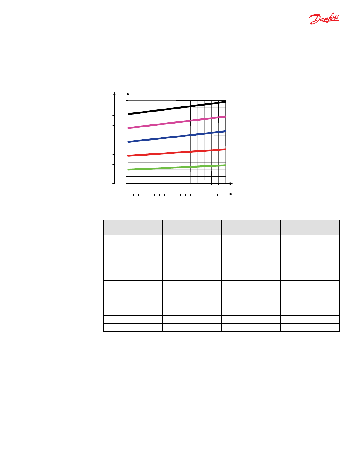
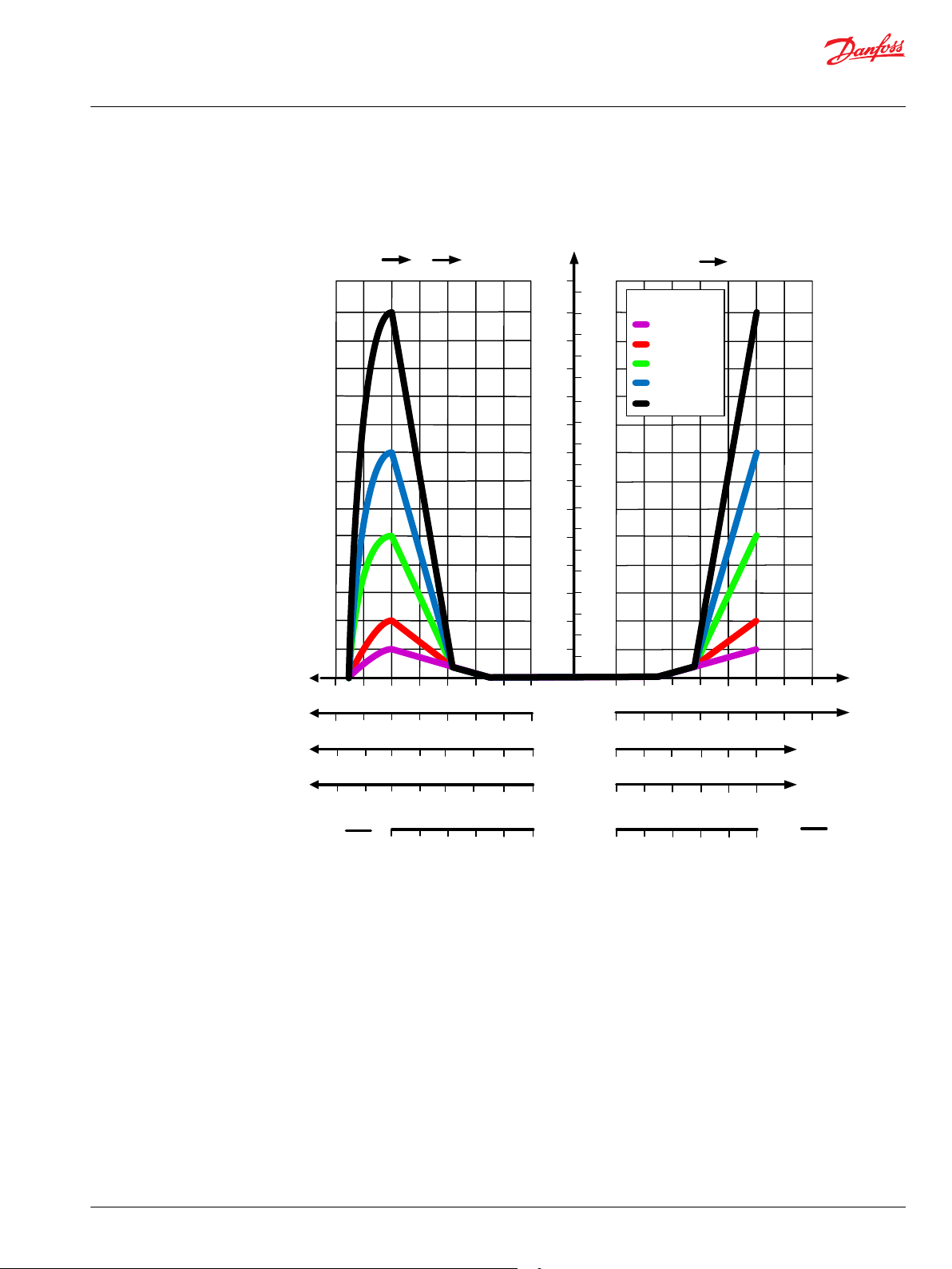
Spool types:
AA = 5/min
A = 10 l/min
B = 25 l/min
C = 40 l/min
D = 65 l/min
17
19
276
247
PVEA
0.50.55
0.6
0.650.7
0.75
0.30.350.4
0.45
0.5
0.25
U
s
U
DC
U
s
U
DC
7
6
Float
Technical Information
PVG 16 Proportional Valve Group
PVB Basic Modules
Performance graphs (Theoretical)
Fluid flow as a function of spool travel - compensated PVB
42 | © Danfoss | July 2021 BC152986484323en-001104

5
10
15
20
25
30
35
40
45
50
55
60
65
(l/min)
[US gal/min]
70
1
2
3
4
5
6
7
8
9
10
11
12
13
14
15
16
17
18
0 25 50 75 100 125 150 175 200 225 250 275 300
0 500 1000 1500 2000 2500 3000 3500 4000
P
AA
B
C
D
A
P
(bar)
[psi]
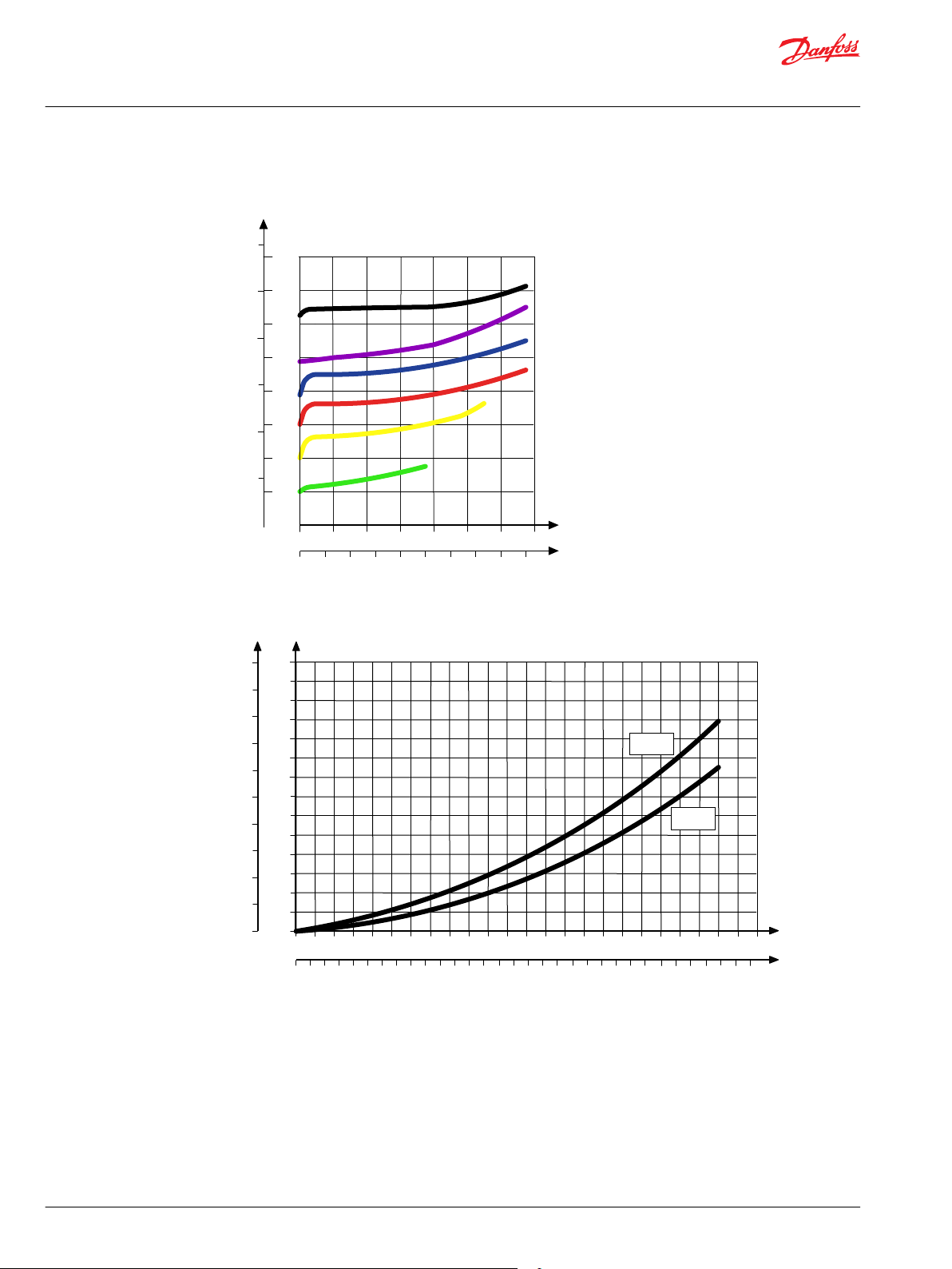
A = 10 l/min
B = 15 l/min
AA = 5/min
C = 25 l/min
D = 40 l/min
Q
Q
P
[psi]
(l/min)
[US gal/min]
5
4,5
4
3,5
3
2,5
2
1,5
1
0,5
0
50
50
40
30
20
10
0
70
75
25
5 10
15
20 25
30
35
40
100
125
150
60
0
0
Port A/B
T-line
P-line
P
(bar)
Technical Information
PVG 16 Proportional Valve Group
PVB Basic Modules
Load Independent Fluid Flow – Pressure Compensated PVB
©
Danfoss | July 2021 BC152986484323en-001104 | 43
PVB pressure compensated P-line and T-line characteristics
Part numbers for compensated PVB
Part number A/B-port
3/8” BSP
3/4” – 16 UNF
11130976
11130977

1
0
2
A
Pp
LX
P
T
B
T0
Technical Information
PVG 16 Proportional Valve Group
PVB Basic Modules
Compensated PVB with PVLP/PVLA
The compensated PVB featuring an optional PVLP/PVLA shock and anti-cavitation valves on each work
port for pressure peak protection and anti-cavitation prevention.
The compensated PVB is intended for controlling a work function where the function behavior in terms
of flow and pressures requires independence on the load pressure of other functions used
simultaneously.
Featuring an optional shock and anti-cavitation valves (PVLP/PVLA ) on each work port for pressure peak
protection and anti-cavitation prevention.
The Compensated PVB with PVLP/PVLA features:
Integrated LS shuttle network
•
Integrated compensator
•
Optional shock/anti-cavitation and suction valves facility (PVLP/PVLA)
•
Compensated PVB with PVLP/PVLA schematic
Technical specification for A/B-port
Max. continuous pressure Max. intermittent pressure Max. rated flow
380 bar [5510 psi] 420 bar [6090 psi] 60 l/min [15 US gal/min]
Technical specification
Parameter Minimum Recommended range Maximum
Fluid temperature
Fluid viscosity
Fluid cleanliness
(mechanical activation)
Fluid cleanliness
(PVE activation)
Operating temperature
-30°C [-22°F] 30 to 60°C [86 to 140°F] 90° [194°F]
4 mm2/s [39 SUS] 12 to 75 mm2/s [65 to 347 SUS] 460 mm2/s [2128 SUS]
23/19/16 (according to ISO 4406)
18/16/13 (according to ISO 4406)
Ambient: -30 to 60°C [-22 to 140°F]
44 | © Danfoss | July 2021 BC152986484323en-001104
B
P
5
10
15
20
25
30
35
40
45
50
55
60
65
[l/min]
[US gal/min]
[mm]
PVM
0
1
2
3
4
5
6
7
[in]
0
0.04
0.08
0.12
0.16
0.20
0.24
0.28
70
1
2
3
4
5
6
7
8
9
10
11
12
13
14
15
16
17
18
A
P
[mm]
5
4
3
[in]
0.28
0.24
0.20
2
0.16
1
0
0.120.080.04
0
bar
AA
B
C
D
A
5791113
15
131197
5
15
PVH
73
218
73
218
psi
psi
bar
189
160
131
102
102 131
160 189
Spool types:
AA = 5/min
A = 10 l/min
B = 25 l/min
C = 40 l/min
D = 65 l/min
17
19
276
247
PVEA
0.50.55
0.6
0.650.7
0.75
0.30.350.4
0.45
0.5
0.25
U
s
U
DC
U
s
U
DC
7
6
Float
Technical Information
PVG 16 Proportional Valve Group
PVB Basic Modules
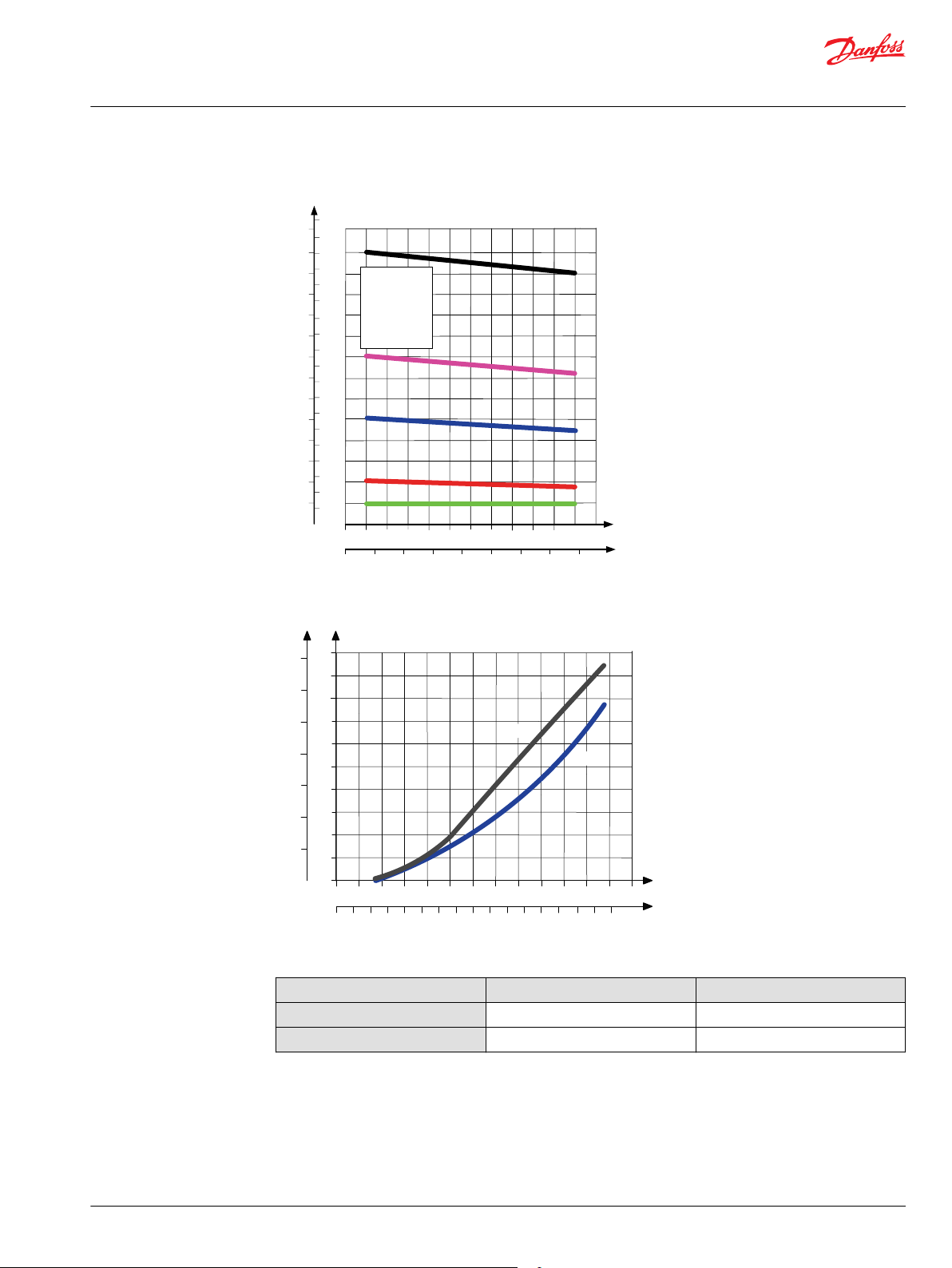
Performance graphs (Theoretical)
Fluid flow as a function of spool travel - compensated PVB
©
Danfoss | July 2021 BC152986484323en-001104 | 45
(l/min)
[US gal/min]
P
Q
Q
(bar)
[psi]
20 40 60 80 100 120 140
5
10 15 20 25 30 35 40 45
400
350
300
250
200
150
100
50
0
5000
4000
3000
2000
1000
0
6000
0
0
5 10 15 20 25 30 35 40 45 50 55 60 65
[l/min]
[US gal/min]
70 75 80
1 2 3 4 5 6 7 8 9 10 11 12 13 14 15 16 17 18 19 20 21
20
18
16
14
12
10
8
6
4
2
0
85 90 95 100
22 23 24 25 26
Q
28
26
24
22
P
P
200
160
120
80
40
0
280
240
320
400
360
0
[psi] [bar]
0
Q
105 110 115 120
27 28 29 30 31
PVLP
PVLA
Technical Information
PVG 16 Proportional Valve Group
PVB Basic Modules
PVLP shock valve characteristics
PVLP/PVLA suction valve characteristics
46 | © Danfoss | July 2021 BC152986484323en-001104
5
10
15
20
25
30
35
40
45
50
55
60
65
(l/min)
[US gal/min]
70
1
2
3
4
5
6
7
8
9
10
11
12
13
14
15
16
17
18
0 25 50 75 100 125 150 175 200 225 250 275 300
0 500 1000 1500 2000 2500 3000 3500 4000
P
AA
B
C
D
A
P
(bar)
[psi]
A = 10 l/min
B = 15 l/min
AA = 5/min
C = 25 l/min
D = 40 l/min
Q
Q
P
[psi]
(l/min)
[US gal/min]
5
4,5
4
3,5
3
2,5
2
1,5
1
0,5
0
50
50
40
30
20
10
0
70
75
25
5 10
15
20 25
30
35
40
100
125
150
60
0
0
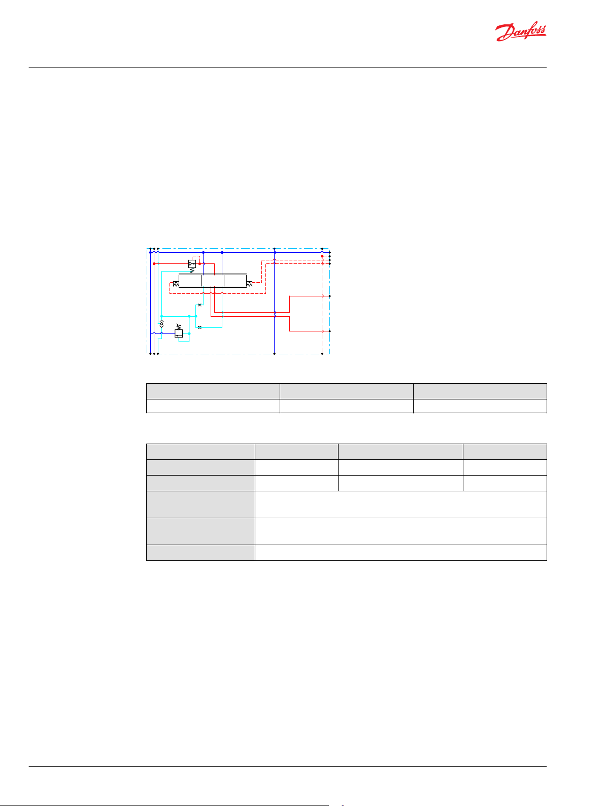
Port A/B
T-line
P-line
P
(bar)
Technical Information
PVG 16 Proportional Valve Group
PVB Basic Modules
Load Independent Fluid Flow – Pressure Compensated PVB
©
Danfoss | July 2021 BC152986484323en-001104 | 47
PVB pressure compensated P-line and T-line characteristics
Part numbers for Compensated PVB with PVLP/PVLA
Part number A/B-port PVLP/PVLA
3/8” BSP 1
3/4” – 16 UNF 1
11130978
11130979
1
0
2
A
Pp
T0
LX
P
T
B
Technical Information
PVG 16 Proportional Valve Group
PVB Basic Modules
Compensated PVB with LS A/B
The compensated PVB is intended for controlling a work function where the function behavior in terms
of flow and pressures requires independency on the load pressure of other functions used
simultaneously. The integrated LS
A/B-ports individually.
The compensated PVB with LS
Integrated LS shuttle network
•
Integrated compensator
•
Compensated PVB with LS A/B schematic
relief valve is used to limit the maximum work port build-up on the
A/B
features:
A/B
Technical specification for A/B-port
Max. continuous pressure Max. intermittent pressure Max. rated flow
350 bar [5076 psi] 420 bar [6090 psi] 60 l/min [15 US gal/min]
Technical specification
Parameter Minimum Recommended range Maximum
Fluid temperature
Fluid viscosity
Fluid cleanliness
(mechanical activation)
Fluid cleanliness
(PVE activation)
Operating temperature
-30°C [-22°F] 30 to 60°C [86 to 140°F] 90° [194°F]
4 mm2/s [39 SUS] 12 to 75 mm2/s [65 to 347 SUS] 460 mm2/s [2128 SUS]
23/19/16 (according to ISO 4406)
18/16/13 (according to ISO 4406)
Ambient: -30 to 60°C [-22 to 140°F]
48 | © Danfoss | July 2021 BC152986484323en-001104

B
P
5
10
15
20
25
30
35
40
45
50
55
60
65
[l/min]
[US gal/min]
[mm]
PVM
0
1
2
3
4
5
6
7
[in]
0
0.04
0.08
0.12
0.16
0.20
0.24
0.28
70
1
2
3
4
5
6
7
8
9
10
11
12
13
14
15
16
17
18
A
P
[mm]
5
4
3
[in]
0.28
0.24
0.20
2
0.16
1
0
0.120.080.04
0
bar
AA
B
C
D
A
5791113
15
131197
5
15
PVH
73
218
73
218
psi
psi
bar
189
160
131
102
102 131
160 189
Spool types:
AA = 5/min
A = 10 l/min
B = 25 l/min
C = 40 l/min
D = 65 l/min
17
19
276
247
PVEA
0.50.55
0.6
0.650.7
0.75
0.30.350.4
0.45
0.5
0.25
U
s
U
DC
U
s
U
DC
7
6
Float
Technical Information
PVG 16 Proportional Valve Group
PVB Basic Modules
Performance graphs (Theoretical)
Fluid flow as a function of spool travel - compensated PVB
©
Danfoss | July 2021 BC152986484323en-001104 | 49
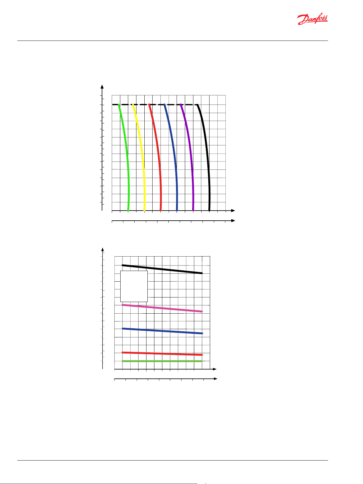
(l/min)
[US gal/min]
P
Q
P
(bar)
[psi]
5
10
15
20
25
30
35
40
45
50
55
60
65
70
1
2
3
4
5
6
7
8
9
10
11
12
13
14
15
16
17
18
250225200175150125
100
755025
0
350
325300275
25002000150010005000 35003000 4000 50004500
0
5
10
15
20
25
30
35
40
45
50
55
60
65
(l/min)
[US gal/min]
70
1
2
3
4
5
6
7
8
9
10
11
12
13
14
15
16
17
18
0 25 50 75 100 125 150 175 200 225 250 275 300
0 500 1000 1500 2000 2500 3000 3500 4000
P
AA
B
C
D
A
P
(bar)
[psi]
A = 10 l/min
B = 15 l/min
AA = 5/min
C = 25 l/min
D = 40 l/min
Technical Information
PVG 16 Proportional Valve Group
PVB Basic Modules
PVB pressure compensated for LS A/B characteristics
Load Independent Fluid Flow – Pressure Compensated PVB
50 | © Danfoss | July 2021 BC152986484323en-001104

Q
Q
P
[psi]
(l/min)
[US gal/min]
5
4,5
4
3,5
3
2,5
2
1,5
1
0,5
0
50
50
40
30
20
10
0
70
75
25
5 10
15
20 25
30
35
40
100
125
150
60
0
0
Port A/B
T-line
P-line
P
(bar)
Technical Information
PVG 16 Proportional Valve Group
PVB Basic Modules
PVB pressure compensated P-line and T-line characteristics
Part numbers for Compensated PVB with LS A/B
Part number A/B-port
11130982
11130983
©
Danfoss | July 2021 BC152986484323en-001104 | 51
3/8” BSP
3/4” – 16 UNF

1
0
2
A
Pp
T0
LX
P
T
B
Technical Information
PVG 16 Proportional Valve Group
PVB Basic Modules
Uncompensated PVB
The uncompensated PVB is intended for controlling a work function where the function behavior in
terms of flow and pressures requires independence on the load pressure of other functions used
simultaneously.
The Uncompensated PVB features:
Integrated LS shuttle network
•
Optional load drop check valve
•
Uncompensated PVB
Technical specification for A/B-port
Max. continuous pressure Max. intermittent pressure Max. rated flow
380 bar [5510 psi] 420 bar [6090 psi] 65 l/min [17 US gal/min]
Technical specification
Parameter Minimum Recommended range Maximum
Fluid temperature
Fluid viscosity
Fluid cleanliness
(mechanical activation)
Fluid cleanliness
(PVE activation)
Operating temperature
-30°C [-22°F] 30 to 60°C [86 to 140°F] 90° [194°F]
4 mm2/s [39 SUS] 12 to 75 mm2/s [65 to 347 SUS] 460 mm2/s [2128 SUS]
23/19/16 (according to ISO 4406)
18/16/13 (according to ISO 4406)
Ambient: -30 to 60°C [-22 to 140°F]
52 | © Danfoss | July 2021 BC152986484323en-001104

B
P
5
10
15
20
25
30
35
40
45
50
55
60
65
[l/min]
[US gal/min]
[mm]
PVM
0
1
2
3
4
5
6
7
[in]
0
0.04
0.08
0.12
0.16
0.20
0.24
0.28
70
1
2
3
4
5
6
7
8
9
10
11
12
13
14
15
16
17
18
A
P
[mm]
5
4
3
[in]
0.28
0.24
0.20
2
0.16
1
0
0.120.080.04
0
bar
AA
B
C
D
A
5791113
15
131197
5
15
PVH
73
218
73
218
psi
psi
bar
189
160
131
102
102 131
160 189
Spool types:
AA = 5/min
A = 10 l/min
B = 25 l/min
C = 40 l/min
D = 65 l/min
17
19
276
247
PVEA
0.50.55
0.6
0.650.7
0.75
0.30.350.4
0.45
0.5
0.25
U
s
U
DC
U
s
U
DC
7
6
Float
Technical Information
PVG 16 Proportional Valve Group
PVB Basic Modules
Performance graphs (Theoretical)
Fluid flow as a function of spool travel - compensated PVB
©
Danfoss | July 2021 BC152986484323en-001104 | 53

Q
Q
P
[psi]
(l/min)
[US gal/min]
5
4,5
4
3,5
3
2,5
2
1,5
1
0,5
0
50
50
40
30
20
10
0
70
75
25
5 10
15
20 25
30
35
40
100
125
150
60
0
0
Port A/B
T-line
P-line
P
(bar)
Technical Information
PVG 16 Proportional Valve Group
PVB Basic Modules
PVB pressure compensated P-line and T-line characteristics
Part numbers for Uncompensated PVB
Part number A/B-port Check valve
11106801
11101421
11106797
11101423
54 | © Danfoss | July 2021 BC152986484323en-001104
3/8” BSP Yes
3/8” BSP —
3/4” – 16 UNF Yes
3/4” – 16 UNF —

1
0
2
A
Pp
LX
P
T
B
Technical Information
PVG 16 Proportional Valve Group
PVB Basic Modules
Uncompensated PVB with PVLP
The uncompensated PVB featuring an optional PVLP shock valve on each work port for pressure peak
protection and anti-cavitation prevention, is intended for controlling a work function where the function
behavior in terms of flow and pressures requires independence on the load pressure of other functions
used simultaneously.
The Uncompensated PVB with PVLP features:
Integrated LS shuttle network
•
Optional shock valve facility (PVLP)
•
Optional load drop check valve
•
Uncompensated PVB with PVLP schematic
Technical specification for A/B-port
Max. continuous pressure Max. intermittent pressure Max. rated flow
380 bar [5510 psi] 420 bar [6090 psi] 65 l/min [17 US gal/min]
Technical specification
Parameter Minimum Recommended range Maximum
Fluid temperature
Fluid viscosity
Fluid cleanliness
(mechanical activation)
Fluid cleanliness
(PVE activation)
Operating temperature
-30°C [-22°F] 30 to 60°C [86 to 140°F] 90° [194°F]
4 mm2/s [39 SUS] 12 to 75 mm2/s [65 to 347 SUS] 460 mm2/s [2128 SUS]
23/19/16 (according to ISO 4406)
18/16/13 (according to ISO 4406)
Ambient: -30 to 60°C [-22 to 140°F]
©
Danfoss | July 2021 BC152986484323en-001104 | 55

B
P
5
10
15
20
25
30
35
40
45
50
55
60
65
[l/min]
[US gal/min]
[mm]
PVM
0
1
2
3
4
5
6
7
[in]
0
0.04
0.08
0.12
0.16
0.20
0.24
0.28
70
1
2
3
4
5
6
7
8
9
10
11
12
13
14
15
16
17
18
A
P
[mm]
5
4
3
[in]
0.28
0.24
0.20
2
0.16
1
0
0.120.080.04
0
bar
AA
B
C
D
A
5791113
15
131197
5
15
PVH
73
218
73
218
psi
psi
bar
189
160
131
102
102 131
160 189
Spool types:
AA = 5/min
A = 10 l/min
B = 25 l/min
C = 40 l/min
D = 65 l/min
17
19
276
247
PVEA
0.50.55
0.6
0.650.7
0.75
0.30.350.4
0.45
0.5
0.25
U
s
U
DC
U
s
U
DC
7
6
Float
Technical Information
PVG 16 Proportional Valve Group
PVB Basic Modules
Performance graphs (Theoretical)
Fluid flow as a function of spool travel - compensated PVB
56 | © Danfoss | July 2021 BC152986484323en-001104

(l/min)
[US gal/min]
P
Q
Q
(bar)
[psi]
20 40 60 80 100 120 140
5
10 15 20 25 30 35 40 45
400
350
300
250
200
150
100
50
0
5000
4000
3000
2000
1000
0
6000
0
0
Q
Q
P
[psi]
(l/min)
[US gal/min]
5
4,5
4
3,5
3
2,5
2
1,5
1
0,5
0
50
50
40
30
20
10
0
70
75
25
5 10
15
20 25
30
35
40
100
125
150
60
0
0
Port A/B
T-line
P-line
P
(bar)
Technical Information
PVG 16 Proportional Valve Group
PVB Basic Modules
PVLP shock valve characteristics
PVB pressure compensated P-line and T-line characteristics
©
Danfoss | July 2021 BC152986484323en-001104 | 57
Part numbers for Uncompensated PVB with PVLP
Part number A/B-port PVLP Check valve
3/8” BSP 1 Yes
3/8” BSP 1 —
3/4” – 16 UNF 1 Yes
3/4” – 16 UNF 1 —
11101424
11106754
11101425
11106755

P109174
Port pressure
(l/min)
[US gal/min]
P
Q
Q
(bar)
[psi]
20 40 60 80 100 120 140
5
10 15 20 25 30 35 40 45
400
350
300
250
200
150
100
50
0
5000
4000
3000
2000
1000
0
6000
0
0
Technical Information
PVG 16 Proportional Valve Group
PVB Basic Modules
PVLP Shock and Anti-Cavitation Valve
The PVLP shock and anti-cavitation valve will relieve a pressure peak to the internal tank galleries and will
furthermore suck oil from the tank to the work port to prevent cavitation. Pressure settings range: 32–400
bar [460–5801 psi].
The pressure setting of the PVLP must always be 20 bar [290 psi] higher than LS
module.
PVLP schematic
PVLP shock valve characteristics
setting in the same
A/B
58 | © Danfoss | July 2021 BC152986484323en-001104

5 10 15 20 25 30 35 40 45 50 55 60 65
[l/min]
[US gal/min]
70 75 80
1 2 3 4 5 6 7 8 9 10 11 12 13 14 15 16 17 18 19 20 21
20
18
16
14
12
10
8
6
4
2
0
85 90 95 100
22 23 24 25 26
Q
28
26
24
22
P
P
200
160
120
80
40
0
280
240
320
400
360
0
[psi] [bar]
0
Q
105 110 115 120
27 28 29 30 31
PVLP
PVLA
Technical Information
PVG 16 Proportional Valve Group
PVB Basic Modules
PVLP/PVLA suction valve characteristics
Technical specification
Parameter Minimum Recommended range Maximum
Fluid temperature
Fluid viscosity
Fluid cleanliness
(mechanical activation)
Fluid cleanliness
(PVE activation)
Operating temperature
Part numbers for PVLP according to pressure settings
Part number Pressure in bar [psi] Part number Pressure in bar [psi]
157B2032 32 [464] 157B2210 210 [3045]
©
Danfoss | July 2021 BC152986484323en-001104 | 59
157B2050 50 [725] 157B2230 230 [3335]
157B2063 63 [913] 157B2240 240 [3480]
157B2080 80 [1160] 157B2250 250 [3626]
157B2100 100 [1450] 157B2265 265 [3844]
157B2125 125 [1813] 157B2280 280 [4061]
157B2140 140 [2031] 157B2300 300 [4351]
157B2150 150 [2176] 157B2320 320 [4641]
157B2160 160 [2321] 157B2350 350 [5076]
157B2175 175 [2538] 157B2380 380 [5511]
157B2190 190 [2756] —
-30°C [-22°F] 30 to 60°C [86 to 140°F] 90° [194°F]
4 mm2/s [39 SUS] 12 to 75 mm2/s [65 to 347 SUS] 460 mm2/s [2128 SUS]
23/19/16 (according to ISO 4406)
18/16/13 (according to ISO 4406)
Ambient: -30 to 60°C [-22 to 140°F]

Technical Information
PVG 16 Proportional Valve Group
PVB Basic Modules Accessories
The generic PVB module accessory platform include the PVLP shock and anti-cavitation valve and PVLA
suction valve.
PVLP Shock and Anti-Cavitation Valve on page 58
•
PVLA Suction Valve on page 63
•
60 | © Danfoss | July 2021 BC152986484323en-001104
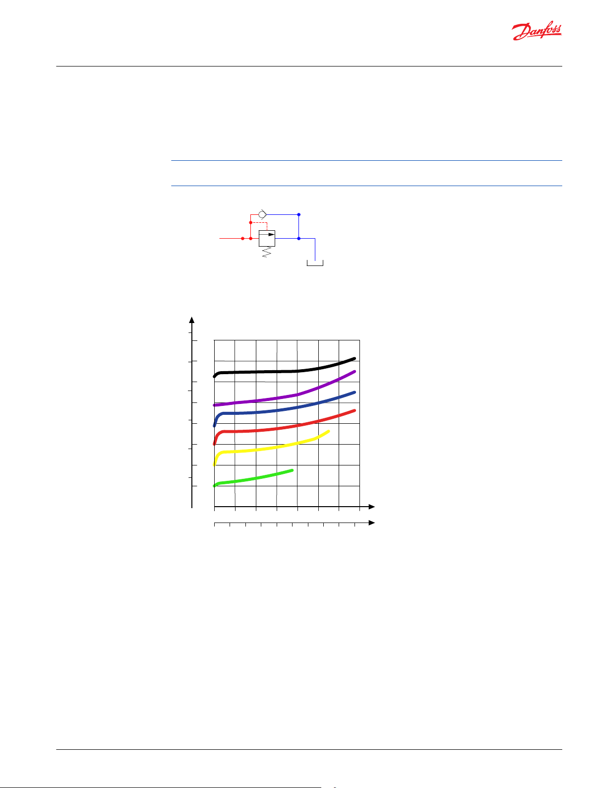
P109174
Port pressure
(l/min)
[US gal/min]
P
Q
Q
(bar)
[psi]
20 40 60 80 100 120 140
5
10 15 20 25 30 35 40 45
400
350
300
250
200
150
100
50
0
5000
4000
3000
2000
1000
0
6000
0
0
Technical Information
PVG 16 Proportional Valve Group
PVB Basic Modules Accessories
PVLP Shock and Anti-Cavitation Valve
The PVLP shock and anti-cavitation valve will relieve a pressure peak to the internal tank galleries and will
furthermore suck oil from the tank to the work port to prevent cavitation. Pressure settings range: 32–400
bar [460–5801 psi].
The pressure setting of the PVLP must always be 20 bar [290 psi] higher than LS
module.
PVLP schematic
PVLP shock valve characteristics
setting in the same
A/B
©
Danfoss | July 2021 BC152986484323en-001104 | 61

5 10 15 20 25 30 35 40 45 50 55 60 65
[l/min]
[US gal/min]
70 75 80
1 2 3 4 5 6 7 8 9 10 11 12 13 14 15 16 17 18 19 20 21
20
18
16
14
12
10
8
6
4
2
0
85 90 95 100
22 23 24 25 26
Q
28
26
24
22
P
P
200
160
120
80
40
0
280
240
320
400
360
0
[psi] [bar]
0
Q
105 110 115 120
27 28 29 30 31
PVLP
PVLA
Technical Information
PVG 16 Proportional Valve Group
PVB Basic Modules Accessories
PVLP/PVLA suction valve characteristics
Technical specification
Parameter Minimum Recommended range Maximum
Fluid temperature
Fluid viscosity
Fluid cleanliness
-30°C [-22°F] 30 to 60°C [86 to 140°F] 90° [194°F]
4 mm2/s [39 SUS] 12 to 75 mm2/s [65 to 347 SUS] 460 mm2/s [2128 SUS]
23/19/16 (according to ISO 4406)
(mechanical activation)
Fluid cleanliness
18/16/13 (according to ISO 4406)
(PVE activation)
Operating temperature
Ambient: -30 to 60°C [-22 to 140°F]
Part numbers for PVLP according to pressure settings
Part number Pressure in bar [psi] Part number Pressure in bar [psi]
157B2032 32 [464] 157B2210 210 [3045]
62 | © Danfoss | July 2021 BC152986484323en-001104
157B2050 50 [725] 157B2230 230 [3335]
157B2063 63 [913] 157B2240 240 [3480]
157B2080 80 [1160] 157B2250 250 [3626]
157B2100 100 [1450] 157B2265 265 [3844]
157B2125 125 [1813] 157B2280 280 [4061]
157B2140 140 [2031] 157B2300 300 [4351]
157B2150 150 [2176] 157B2320 320 [4641]
157B2160 160 [2321] 157B2350 350 [5076]
157B2175 175 [2538] 157B2380 380 [5511]
157B2190 190 [2756] —

P109175
Port pressure
5 10 15 20 25 30 35 40 45 50 55 60 65
[l/min]
[US gal/min]
70 75 80
1 2 3 4 5 6 7 8 9 10 11 12 13 14 15 16 17 18 19 20 21
20
18
16
14
12
10
8
6
4
2
0
85 90 95 100
22 23 24 25 26
Q
28
26
24
22
P
P
200
160
120
80
40
0
280
240
320
400
360
0
[psi] [bar]
0
Q
105 110 115 120
27 28 29 30 31
PVLP
PVLA
Technical Information
PVG 16 Proportional Valve Group
PVB Basic Modules Accessories
PVLA Suction Valve
The PVLA valve is an accessory available for PVB basic modules.
The PVLA will suck fluid from the tank to the work port to prevent cavitation by the 0.5 bar spring. The
plug will ensure that when using a single acting spool, all flow returning through the work port is led to
tank.
PVLA schematic
PVLP/PVLA suction valve characteristics
Technical specification
Parameter Minimum Recommended range Maximum
Fluid temperature
Fluid viscosity
Fluid cleanliness
(mechanical activation)
Fluid cleanliness
(PVE activation)
Operating temperature
PVLA suction valve part number
PVLA suction valve Plug
©
Danfoss | July 2021 BC152986484323en-001104 | 63
157B2001 157B2002
-30°C [-22°F] 30 to 60°C [86 to 140°F] 90° [194°F]
4 mm2/s [39 SUS] 12 to 75 mm2/s [65 to 347 SUS] 460 mm2/s [2128 SUS]
23/19/16 (according to ISO 4406)
18/16/13 (according to ISO 4406)
Ambient: -30 to 60°C [-22 to 140°F]

110 [4.33]
46 [1.81]
14,8 [0.59]
Technical Information
PVG 16 Proportional Valve Group
PVBS Main Spools
The main spools (PVBS) determine the flow out of the work section or the pressure build up and are
based on a generic platform with a wide selection of additional features, enabling you to tailor the PVBS
to suit the demands of any hydraulic system and any function.
The PVBS main spool can be activated in three different ways:
•
Mechanically by a PVM lever
•
Electrically by a PVE/PVHC actuator
•
Hydraulically by a PVH actuator
PVBS main spool
PVBS main spool dimensions
Weight: 0.16 kg [0.35 lb]
General features
•
4-way, positions
•
Optional 4-way, 4 positions with the right PVM
•
Flow control AB
•
Dead band 1.2mm [0.047 in]
PVBS Technical Parameters
Technical specification
Parameter Minimum Recommended range Maximum
Fluid temperature
Fluid viscosity
Fluid cleanliness
(mechanical activation)
Fluid cleanliness
(PVE activation)
Operating temperature
-30°C [-22°F] 30 to 60°C [86 to 140°F] 90° [194°F]
4 mm2/s [39 SUS] 12 to 75 mm2/s [65 to 347 SUS] 460 mm2/s [2128 SUS]
23/19/16 (according to ISO 4406)
18/16/13 (according to ISO 4406)
Ambient: -30 to 60°C [-22 to 140°F]
64 | © Danfoss | July 2021 BC152986484323en-001104

B
P
5
10
15
20
25
30
35
40
45
50
55
60
65
[l/min]
[US gal/min]
[mm]
PVM
0
1
2
3
4
5
6
7
[in]
0
0.04
0.08
0.12
0.16
0.20
0.24
0.28
70
1
2
3
4
5
6
7
8
9
10
11
12
13
14
15
16
17
18
A
P
[mm]
5
4
3
[in]
0.28
0.24
0.20
2
0.16
1
0
0.120.080.04
0
bar
AA
B
C
D
A
5791113
15
131197
5
15
PVH
73
218
73
218
psi
psi
bar
189
160
131
102
102 131
160 189
Spool types:
AA = 5/min
A = 10 l/min
B = 25 l/min
C = 40 l/min
D = 65 l/min
17
19
276
247
PVEA
0.50.55
0.6
0.650.7
0.75
0.30.350.4
0.45
0.5
0.25
U
s
U
DC
U
s
U
DC
7
6
Float
Technical Information
PVG 16 Proportional Valve Group
PVBS Main Spools
PVBS Fluid Flow Characteristics - Theoretical Performance
Fluid flow as a function of spool travel - compensated PVB
©
Danfoss | July 2021 BC152986484323en-001104 | 65

5
10
15
20
25
30
35
40
45
50
55
60
65
[mm]
0
1
2
3
4
5
6
7
[in]
PVM
0
0.04
0.08
0.12
0.16
0.20
0.24
0.28
PVEA
U
s
U
DC
0.5
0.55
0.6
0.65
0.7
0.75
70
1
2
3
4
5
6
7
8
9
10
11
12
13
14
15
16
17
18
[l/min]
[US gal/min]
[mm]
6
5
[in]
0.24
0.20
U
s
U
DC
0.35
0.4
0.45
4
0.16
0.5
3
2
1
0
0.12
0.08
0.04
0
A
B
C
D
E
AA
A
B
C
D
E
AA
Spool types:
AA = 5/min
A = 10 l/min
B = 15 l/min
C = 25 l/min
D = 40 l/min
E = 65 l/min
BP
AP
0.250.3
bar
PVH
579
11
1315
17
19
bar
1715
13
11
9
7
5
psi
PVH
73102
131
160189218
247
276
psi
247218
189160
131102
73
Technical Information
PVG 16 Proportional Valve Group
PVBS Main Spools
Fluid flow as a function of spool travel (asymmetrical spools)
66 | © Danfoss | July 2021 BC152986484323en-001104

5 10 15 20 25 30
[l/min]
[US gal/min]
35 40
1 2 3 4 5 6 7 8 9 10
200
180
160
140
120
100
80
60
40
20
45 50
11 12 13
Q
280
260
240
220
P
P
2000
1600
1200
800
400
0
2800
2400
3200
4000
3600
0
[psi]
0
Q
55 60
14 15
(bar)
Pressure drop for
PVBS 65 l/min
Technical Information
PVG 16 Proportional Valve Group
PVBS Main Spools
Pressure drop to T (open spool in neutral)
©
Danfoss | July 2021 BC152986484323en-001104 | 67

Technical Information
PVG 16 Proportional Valve Group
PVBS Main Spools Part Numbers
Flow Control Spools - Closed Neutral Position
Schematic for PVBS - 4-way, 3 positions Schematic for PVBS - 4-way, 4 positions
Symmetrical spools
Part number Actuation
11105532 PVE 5 [1.32] 5 [1.32] 5 [1.32] 5 [1.32]
11105533 PVE 10 [2.64] 10 [2.64] 10 [2.64] 10 [2.64]
11105534 PVE 25 [6.60] 25 [6.60] 25 [6.60] 25 [6.60]
11105535 PVE 40 [10.57] 40 [10.57] 40 [10.57] 40 [10.57]
11105536 PVE 65 [17.17] 65 [17.17] 65 [17.17] 65 [17.17]
11109632 PVH/PVHC 5 [1.32] 5 [1.32] 5 [1.32] 5 [1.32]
11109633 PVH/PVHC 10 [2.64] 10 [2.64] 10 [2.64] 10 [2.64]
11109634 PVH/PVHC 25 [6.60] 25 [6.60] 25 [6.60] 25 [6.60]
11109635 PVH/PVHC 40 [10.57] 40 [10.57] 40 [10.57] 40 [10.57]
11109636 PVH/PVHC 65 [17.17] 65 [17.17] 65 [17.17] 65 [17.17]
*
All spools can be mechanically actuated with a PVM, for more details see PVM Manual Actuation on page 71
*
Flow – l/min [US gal/min]
A → T P → A P → B B → T
Asymmetrical Spools
Part number Actuation
11109642 PVE 5 [1.32] 5 [1.32] 2.5 [0.66] 2.5 [0.66]
11109643 PVE 10 [2.64] 10 [2.64] 5 [1.32] 5 [1.32]
11156296 PVE 15 [3.96] 15 [3.96] 25 [6.60] 25 [6.60]
11109644 PVE 25 [6.60] 25 [6.60] 10 [2.64] 10 [2.64]
11109645 PVE 25 [6.60] 25 [6.60] 15 [3.96] 15 [3.96]
11156298 PVE 25 [6.60] 25 [6.60] 40 [10.57] 40 [10.57]
11109646 PVE 40 [10.57] 40 [10.57] 15 [3.96] 15 [3.96]
11146752 PVH/PVHC 5 [1.32] 5 [1.32] 2.5 [0.66] 2.5 [0.66]
11146753 PVH/PVHC 10 [2.64] 10 [2.64] 5 [1.32] 5 [1.32]
11145754 PVH/PVHC 25 [6.60] 25 [6.60] 10 [2.64] 10 [2.64]
11146755 PVH/PVHC 25 [6.60] 25 [6.60] 15 [3.96] 15 [3.96]
11146756 PVH/PVHC 40 [10.57] 40 [10.57] 15 [3.96] 15 [3.96]
11146757 PVH/PVHC 40 [10.57] 40 [10.57] 25 [6.60] 25 [6.60]
*
All spools can be mechanically actuated with a PVM, for more details see PVM Manual Actuation on page 71
*
Flow – l/min [US gal/min]
A → T P → A P → B B → T
68 | © Danfoss | July 2021 BC152986484323en-001104

Technical Information
PVG 16 Proportional Valve Group
PVBS Main Spools Part Numbers
Flow Control Spools - Throttled Open Neutral Position
Schematic for PVBS - 4-way, 3 positions Schematic for PVBS - 4-way, 4 positions
Symmetrical Spools
Part number Actuation
11105537 PVE 5 [1.32] 5 [1.32] 5 [1.32] 5 [1.32]
11105538 PVE 10 [2.64] 10 [2.64] 10 [2.64] 10 [2.64]
11105539 PVE 25 [6.60] 25 [6.60] 25 [6.60] 25 [6.60]
11105540 PVE 40 [10.57] 40 [10.57] 40 [10.57] 40 [10.57]
11105541 PVE 65 [17.17] 65 [17.17] 65 [17.17] 65 [17.17]
11109637 PVH/PVHC 5 [1.32] 5 [1.32] 5 [1.32] 5 [1.32]
11109638 PVH/PVHC 10 [2.64] 10 [2.64] 10 [2.64] 10 [2.64]
11109639 PVH/PVHC 25 [6.60] 25 [6.60] 25 [6.60] 25 [6.60]
11109640 PVH/PVHC 40 [10.57] 40 [10.57] 40 [10.57] 40 [10.57]
11109641 PVH/PVHC 65 [17.17] 65 [17.17] 65 [17.17] 65 [17.17]
*
All spools can be mechanically actuated with a PVM, for more details see PVM Manual Actuation on page 71
*
Flow – l/min [US gal/min]
A → T P → A P → B B → T
Asymmetrical Spools
Part number Actuation
11160953 PVE 5 [1.32] 5 [1.32] 2.5 [0.66] 2.5 [0.66]
11159472 PVE 5 [1.32] 5 [1.32] 5 [1.32] 5 [1.32]
11156160 PVE 15 [3.96] 15 [3.96] 25 [6.60] 25 [6.60]
11156158 PVE 25 [6.60] 25 [6.60] 40 [10.57] 40 [10.57]
11160957 PVE 40 [10.57] 40 [10.57] 25 [6.60] 25 [6.60]
11156155 PVE 40 [10.57] 40 [10.57] 65 [17.17] 65 [17.17]
11189195 PVH/PVHC 15 [3.96] 15 [3.96] 25 [6.60] 25 [6.60]
*
All spools can be mechanically actuated with a PVM, for more details see PVM Manual Actuation on page 71
*
Flow – l/min [US gal/min]
A → T P → A P → B B → T
©
Danfoss | July 2021 BC152986484323en-001104 | 69
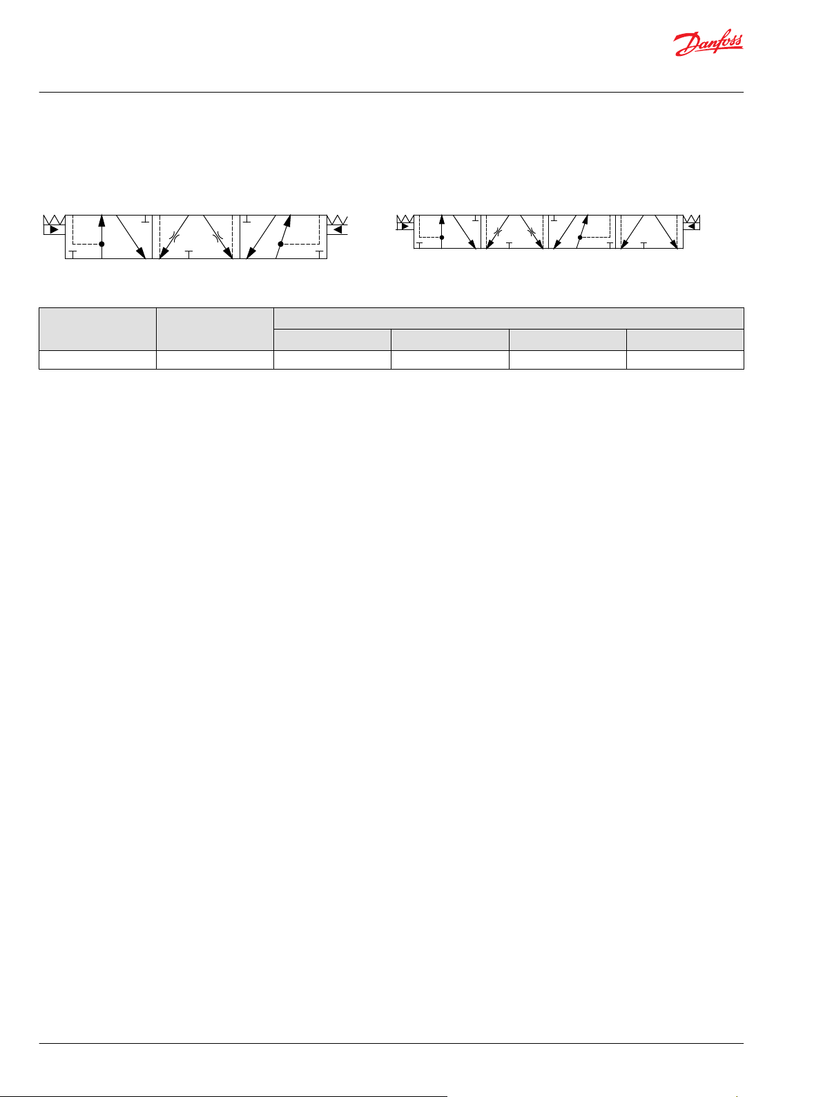
Technical Information
PVG 16 Proportional Valve Group
PVBS Main Spools Part Numbers
Flow Control Spools - Open/Closed Neutral Position
Schematic for PVBS - 4-way, 3 positions Schematic for PVBS - 4-way, 4 positions
Asymmetrical Spools
Part number Actuation
11179510 PVE 15 [3.96] 15 [3.96] 5 [1.32] 15 [3.96]
*
All spools can be mechanically actuated with a PVM, for more details see PVM Manual Actuation on page 71
*
Flow – l/min [US gal/min]
A → T P → A P → B B → T
70 | © Danfoss | July 2021 BC152986484323en-001104

183.8 [7.24]
85 [3.35]
60 [2.36]
13 [0.51]
45.6 [1.80]
51.7 [2.04]
Technical Information
PVG 16 Proportional Valve Group
PVG 16 Actuation
PVG 16 actuation can be done manually, hydraulically, electro-hydraulically and electrically.
PVG 16 actuation overview:
PVM Manual Actuation on page 71
•
PVMD Cover on page 72
‒
PVH Hydraulic Actuation on page 73
•
PVHC Electro-Hydraulic Actuation on page 75
•
PVE Electro-hydraulic Actuation on page 77
•
PVEO on page 79
‒
PVEA Series 6 Proportional Control Actuator on page 82
‒
PVM Manual Actuation
The PVM manual actuation cover is intended for use on any work section where the operator has to have
the ability to interact with the spool manually.
The PVM variants are based on a generic platform with a selection of additional features, enabling you to
tailor the PVM to suit the demands of any hydraulic system, which includes the following main variants:
•
PVM manual actuation or override of a function
•
Spring centering cover without manual override (PVML)
Optional with lever base
‒
Optional with lever base and lever
‒
Optional flow adjustment screws
‒
The adjustment screws are intended for limiting the spool travel and thereby the maximum achievable
flow.
PVM cover PVM dimensions
Control lever data
Standard control range Control lever range + float position
± 13.9° 22.3°
©
Danfoss | July 2021 BC152986484323en-001104 | 71

86 [3.39]
39 [1.54]
14 [0.55]
Technical Information
PVG 16 Proportional Valve Group
PVG 16 Actuation
PVM torque data
Spool displacement
From neutral position
Max. spool travel
Part numbers for PVM Manual Actuation
Part number Float Adjustment screws Lever base and lever Weight
11107332
11107333
11107335
11107505
11107506
11107507
PVM+PVMD
PVM+PVE
2.2 ± 0.2 N•m
[19.5 ± 1.8 lb•in]
2.8 ± 0.2 N•m
[24.8 ± 1.8 lb•in]
— Yes Yes
— — Yes
Yes — Yes
— — —
Yes — —
— Yes —
PVM+PVH
2.7 ± 0.2 N•m
[23.9 ± 1.8 lb•in]
7.1 ± 0.2 N•m
[62.8 ± 1.8 lb•in]
0,22 kg
[0,49 lb]
PVMD Cover
The PVMD cover is used when work section is purely mechanical activated.
PVMD Cover Dimensions, mm [in]
Part number and weight for PVMD Cover
Part number 11105518
Weight 1.5 kg [3.3 lb]
72 | © Danfoss | July 2021 BC152986484323en-001104

86 [3.39]
27 [1.06]29 [1.14]
39 [1.55]
28 [1.1]
19.5 [0.77]
Technical Information
PVG 16 Proportional Valve Group
PVG 16 Actuation
PVH Hydraulic Actuation
The PVH hydraulic actuation is intended for use on any work section where the operator wants to have a
possibility to interact with the main spool via a hydraulic joystick. The spool spring package must match
with this activation method.
PVH cover PVH 16 cover dimensions
The hydraulic remote control lever should be connected directly to the tank.
©
Danfoss | July 2021 BC152986484323en-001104 | 73

B
P
5
10
15
20
25
30
35
40
45
50
55
60
65
[l/min]
[US gal/min]
[mm]
PVM
0
1
2
3
4
5
6
7
[in]
0
0.04
0.08
0.12
0.16
0.20
0.24
0.28
70
1
2
3
4
5
6
7
8
9
10
11
12
13
14
15
16
17
18
A
P
[mm]
5
4
3
[in]
0.28
0.24
0.20
2
0.16
1
0
0.120.080.04
0
bar
AA
B
C
D
A
5791113
15
131197
5
15
PVH
73
218
73
218
psi
psi
bar
189
160
131
102
102 131
160 189
Spool types:
AA = 5/min
A = 10 l/min
B = 25 l/min
C = 40 l/min
D = 65 l/min
17
19
276
247
7
6
Float
Technical Information
PVG 16 Proportional Valve Group
PVG 16 Actuation
Fluid flow as a function of spool travel - PVH
Technical data
Main spool spring control pressure range
Maximum pilot oil pressure
Maximum pressure on port T
Part numbers for PVH Hydraulic Actuation
Part number Material Connection Weight
11108380
11108381 9/16"-18 UNF
74 | © Danfoss | July 2021 BC152986484323en-001104
Aluminum
5 – 15 bar [73 – 218 psi]
30 bar [435 psi]
10 bar [145 psi]
G1/4" BSP
0,13 kg
[0.29 lb]

92 [3.62]
39 [1.55]
100.5 [3.96]
Technical Information
PVG 16 Proportional Valve Group
PVG 16 Actuation
PVHC Electro-Hydraulic Actuation
The PVHC is an electrical actuator module for main spool control. The PVHC control is done by dual Pulse
Width Modulated, high current supply 100-400 Hz PWM control signals. The spool position will shift
when conditions are changed such as temperature change.
Inlet with Hydraulic Pilot Pressure is needed.
PVHC, Electro-Hydraulic Actuator PVHC dimensions
Weight: 0,9 kg [1,98 lb]
PVHC schematic
Dither frequency with a certain amplitude is needed for optimal application performance.
©
Danfoss | July 2021 BC152986484323en-001104 | 75
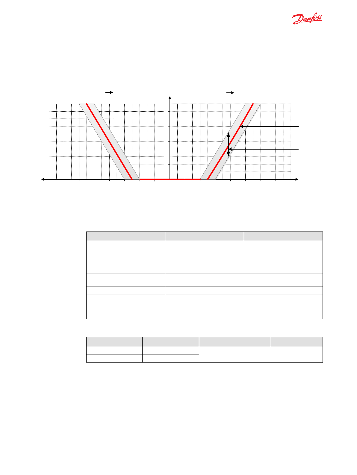
AP
1
2
3
4
5
6
7
8
9
10
0
0
200
100
400
200
600
300
800
400
1000
500
BP
800
400
600
300
400
200
200
100
1000
500
[Current in mA][Current in mA]
@12V
@24V
@12V
@24V
1600
800
1400
700
1200
600
1200
600
1600
800
1400
700
Spool stroke, mm
PVHC characteristics – Spool stroke vs current
Ideal curve
Hysteresis
P109250
Technical Information
PVG 16 Proportional Valve Group
PVG 16 Actuation
PVHC spool stroke vs current characteristics
The hysteresis is affected by viscosity, friction, flow forces, dither frequency and modulation frequency.
Technical data
Supply Voltage U
DC
Current input 0 – 1500 mA 0 – 750 mA
Resistance 4.75 Ω ± 5 % 20.8 Ω ± 5 %
Response time 150 to 200 ms
PWM frequency 100 to 400 Hz
Main spool spring control pressure
range
Pilot oil pressure range 20 – 25 bar [290 – 362 psi]
Ambient temperature range -30°C to 80°C [-22 °F to 176°F]
Temperature range -20°C to 80°C [-4 °F to 176°F]
Fluid cleanliness 23/19/16 (according to ISO 4406)
12 V
DC
5 – 15 bar [73 – 218 psi]
24 V
DC
Part numbers for PVHC Actuators
Part number Power supply Connector type Protection Class
11126941 12V
11127535 24V
76 | © Danfoss | July 2021 BC152986484323en-001104
2x2 DEUTSCH IP 67

Technical Information
PVG 16 Proportional Valve Group
PVG 16 Actuation
PVE Electro-hydraulic Actuation
The analog PVE Series 6 is an electro-hydraulic actuator used to control a single work section of a PVG
proportional valve group. The PVE actuator program for PVG 16 includes variants with different
performance levels and features.
The actuator positions the main spool in a PVG work section to control either the flow or the pressure of
the oil distributed to and from the work function. The control signal to the actuator is an analog voltage
signal, enabling the user to operate the work function remotely by means of a joystick, a controller or the
similar.
The electro-hydraulic solenoid valve bridge of the actuator is available in different designs utilizing
different regulation principles, depending on performance variant. The actuator positions the main spool
by distributing pilot oil pressure to either side of it, pressurizing one side by pilot pressure while relieving
the opposite side to tank and vice versa. All proportional actuators feature a closed- loop spool control
and continuous fault monitoring.
The analog PVE Series 6 actuator program for PVG 16 features two different main hydraulic principle
variants (PVEO and PVEA).
The different hydraulic principles combined with the different solenoid valve regulation principles
determine whether the actuator controls the spool proportionally according to a demand signal or
ON/OFF according to a voltage signal. The voltage control characteristic of the PVE actuators is shown in
the figure below on the left side.
PVG 16 with PVEO sectional view
©
Danfoss | July 2021 BC152986484323en-001104 | 77

Technical Information
PVG 16 Proportional Valve Group
PVG 16 Actuation
PVG 16 with PVEA sectional view
PVE Series 6 Overview
ON/OFF voltage control, non-proportional functions Proportional spool control for work functions
PVEO Series 6
For more information please see PVEO on page 79.
PVEA Series 6
78 | © Danfoss | July 2021 BC152986484323en-001104

21
0
Pp
SV2SV1
LED Circuit (PCB)
LED
Power
Supply
U
DC
A
B
) ( ) (
Technical Information
PVG 16 Proportional Valve Group
PVG 16 Actuation
PVEO
The PVEO actuator is a non-proportional ON/OFF control actuator with open-loop spool control primarily
used to control simple ON/OFF work functions where a proportional control of speed or oil flow is not a
requirement.
PVEO Series 6
•
Neutral position or max. spool stroke according to control signal
•
12 VDC or 24 VDC supply voltage
•
DEUTSCH connectors
•
Standard PVE pilot oil pressure of 13.5 bar [196 psi]
•
LED only indicating Power ON or Power OFF
•
CAN-interface (-CI)
Functionality principle
PVEO functionality diagram
The standard PVEO functionality includes the simplest electric circuit of the PVE actuator program, using
a fixed 12 VDC or 24 VDC supply voltage or signal voltage and a simple LED circuit to control the LED light
indicating Power ON/OFF.
An energization of solenoid valve SV1 and a simultaneous de-energization of SV2 will cause the main
spool to move to the right direction and vice versa. If both SV1 and SV2 are energized or de-energized
simultaneously, the main spool stays locked in its neutral position.
©
Danfoss | July 2021 BC152986484323en-001104 | 79
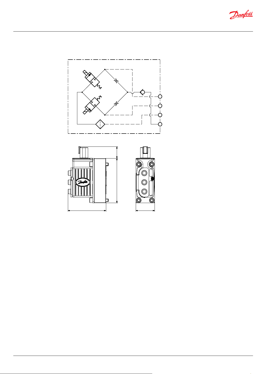
24 [0.94]
92 [3.62]
78.5 [3.09]
39 [1.54]
Technical Information
PVG 16 Proportional Valve Group
PVG 16 Actuation
PVEO Series 6 schematic
PVEO Series 6 dimensions
Weight: 0.7 kg [1.54 lb]
80 | © Danfoss | July 2021 BC152986484323en-001104

Technical Information
PVG 16 Proportional Valve Group
PVG 16 Actuation
PVEO Technical Data
Control Specifications
Description Type 12 VDC ± 10% 24 VDC ± 10%
Supply Voltage (UDC) Range 11 to 15 V
Current Consumption Typical 320 mA 160 mA
Pilot pressure
Minimum Nominal Maximum
10.0 bar [145 psi] 13.5 bar [196 psi] 15.0 bar [218 psi]
Fluid consumption
Neutral/Locked position Actuating
0.04 l/min [0.11 US gal/min] 0.6 l/min [0.16 US gal/min]
DC
Max. ripple 5% 5%
22 to 30 V
DC
Technical specification
Parameter Minimum Recommended range Maximum
Fluid viscosity
Fluid cleanliness
Storage temperature
Operating temperature
4 mm2/s [39 SUS] 12 to 75 mm2/s [65 to 347 SUS] 460 mm2/s [2128 SUS]
18/16/13 (according to ISO 4406)
Ambient: -50 to 90°C [-58 to 194°F]
Ambient: -40 to 90°C [-40 to 194°F]
LED characteristic
Color LED characteristic Description
Green constant Power ON
PVEO/PVEO-CI reaction time
Reaction time A-direction B-direction
Neutral to full stroke 173 ms 105 ms
Full spool stroke to neutral 396 ms 565 ms
Part numbers for PVEO and PVEO-CI
Part number Type Connector Protection Class Voltage Interface
11106793
11106794
11124002
11149443
PVEO 1x4 DEUTSCH IP 67 12 V
PVEO 1x4 DEUTSCH IP 67 24 V
PVEO-CI 2x4 DEUTSCH IP 67 — J1939/ISObus
PVEO-CI 2x4 DEUTSCH IP 67 — CANopen
DC
DC
—
—
©
Danfoss | July 2021 BC152986484323en-001104 | 81

Technical Information
PVG 16 Proportional Valve Group
PVG 16 Actuation
PVEA Series 6 Proportional Control Actuator
The PVEA actuator is a proportional control actuator with a closed-loop spool control primarily used to
control work functions with above medium performance requirements
PVEA Series 6
The PVEA functionality includes an electric circuit with a closed-loop logic. An integrated feedback
transducer measures spool movement in relation to the input signal. The PVEA features passive fault
monitoring, LED indicating fault state, error output pin and Power Save mode.
PVEA functionality
Power Save mode is entered when the command signal to the PVEA is below 15% of the supply voltage.
Entering Power Save mode will torn off the power to the solenoid valves. Power Save mode can be
identified by the LED blinking green at 1 Hz.
All variants available with following features:
•
Neutral position or max. spool stroke according to control signal
•
11–32 VDC multi-voltage power supply
•
DEUTSCH connectors
•
Standard PVE pilot oil pressure of 13.5 bar [196 psi]
•
LED indicating error state and passive fault monitoring
•
Float (-F) and CAN-interface (-CI)
82 | © Danfoss | July 2021 BC152986484323en-001104

24 [0.94]
92 [3.62]
78.5 [3.09]
39 [1.54]
Technical Information
PVG 16 Proportional Valve Group
PVG 16 Actuation
PVEA (-F) Series 6 schematic
PVEA (-F) Series 6 dimensions
Weight: 0.7 kg [1.54 lb]
PVEA Technical Data
PVEA/PVEA-CI/PVEA-F actuator technical specification and part numbers.
Control specification
Description Type Value
Supply voltage (UDC) Rated/range 11 to 32 V
DC
Max. ripple 15 bar [218 psi]
Signal voltage (US) Neutral 0.5 U
Q: P -> A 0.25 U
Q: P -> B 0.75 U
Current consumption @ 12 V
@ 24 V
DC
DC
DC
DC
DC
320 mA
170 mA
Input impedance Rated 12 kΩ
Input capacitance Rated 100 µF
Technical data
Pilot pressure Nominal 13.5 bar [196 psi]
Minimum 10.0 bar [145 psi]
Maximum 15.0 bar [218 psi]
©
Danfoss | July 2021 BC152986484323en-001104 | 83

Technical Information
PVG 16 Proportional Valve Group
PVG 16 Actuation
Technical data (continued)
Fluid consumption Neutral 0.04 l/min [0.01 US gal/min]
Fluid temperature Ambient Storage -50 to +90°C [-58 to +194°F]
Fluid viscosity Operating range 12 to 75 mm2/sec [65 to 347 SUS]
Fluid cleanliness Minimum 18/16/13 (according to ISO 4406)
LED characteristic
Color LED characteristic Description
Green constant No error – Actuating
Green flashing @ 1.5 Hz Neutral – Power save
Red constant Internal error
Red flashing @ 1.5 Hz External or Float error
Locked position 0.04 l/min [0.01 US gal/min]
Actuating 0.6 l/min [0.16 US gal/min]
Ambient Operating -40 to +90°C [-40 to +194°F]
Minimum 4 mm2/sec [39 SUS]
Maximum 460 mm2/sec [2128 SUS]
PVEA/PVEA-F/PVEA-CI reaction time
Reaction time A-direction B-direction
Neutral to full spool stroke 188 ms 142 ms
Full spool stroke to neutral 125 ms 120 ms
Part numbers for PVEA/PVEA-F/PVEA-CI
Part number Type Connector Protection Class Interface Functionality
11103692
11106795
11121945
11149437
PVEA 1x4 DEUTSCH IP 67 — Standard
PVEA-F 1x6 DEUTSCH IP 67 — Float B-port
PVEA-CI 1x4 DEUTSCH IP 67 J1939/ISObus Standard
PVEA-CI 1x4 DEUTSCH IP 67 CANopen Standard
84 | © Danfoss | July 2021 BC152986484323en-001104

2 3
41
2 3
41
23
4 1
1
2
3 4
5
6
Technical Information
PVG 16 Proportional Valve Group
PVG 16 Actuation
PVG 16 connector variants
PVG 16 connector variants for PVEO, PVEA, PVEO-CI, PVEA-CI, PVEA-F with pin layout information.
Pin connector
1 x 4 DEUTSCH 2 x 4 DEUTSCH 1 x 6 DEUTSCH
Pin layout for PVEO, PVEA, PVEO-CI, PVEA-CI
PVE Type Connector Pin 1 Pin 2 Pin 3 Pin 4
PVEO 1 x 4 DEUTSCH NC2 Vneg Vneg NC4
PVEA 1 x 4 DEUTSCH Vi SP Vneg Vbat
PVEO-CI, PVEA-CI 2 x 4 DEUTSCH CAN_H CAN_L Vbat Vneg
Pin layout for PVEA-F
Connector Pin 1 Pin 2 Pin 3 Pin 4 Pin 5 Pin 6
1 x 6 DEUTSCH Vi NC Vf SP Vneg Vbat
©
Danfoss | July 2021 BC152986484323en-001104 | 85

Technical Information
PVG 16 Proportional Valve Group
Fault Monitoring and Reaction
All proportional control PVG 16 actuators feature:
Integrated fault monitoring
•
Detecting spool stroke inconsistencies
•
Detecting internal hardware defects
•
Detecting demand signal inconsistencies
•
Fault reaction depending on the type of fault monitoring
•
Generic
‒
Specific
‒
The PVEA comes with a passive fault monitoring.
Passive fault monitoring
Passive fault monitoring does not disable the solenoid valves when an error is detected. It will continue
to operate despite that an error was detected. When the error no longer is registered the passive fault
monitoring will “forget” the error and continue as if the error was never there.
With a passive fault monitoring the following conditions will happen when an error is detected/occurs:
The LED light will switch from green to red and the error pin output will go high
•
The solenoid valves will continue operating at the set point given at the time of the error
•
Only exception is if the error is caused by the supply voltage (UDC) being either above or below
‒
the allowed range or if the temperature measured on the internal electronics board is higher than
allowed. In these cases, the solenoid valves will be disabled.
Generic Fault Reaction
All PVE actuators with fault monitoring are triggered by the following main events:
Control Signal Monitoring
Transducer/LVDT Supervision
Supervision of Spool Position
Float Position Monitoring
Temperature Monitoring
The Control signal voltage (US) is continuously monitored.
The permissible range is between 15% and 85% of the supply voltage (UDC).
Outside this range the PVE will switch into an error state. A disconnected U
pin (floating) is recognized as a neutral set point.
The internal LVDT wires are monitored. If the signals are interrupted or shortcircuited, the PVE will switch into an error state.
The actual position must always correspond to the demanded position (US).
If the actual spool position is further out from neutral than the demanded
spool position or in opposite direction, the PVE will switch into an error state.
Spool position closer to neutral and in same direction will not cause an error
state – the situation is considered in control.
Float position must be entered or left within a time limit.
A too high delay on the 1x6 pin float PVE will cause an error state – this is
relevant for the 1x6 pin PVEH-F actuators only.
When the temperature is too high the PVE LED will light constant red and
solenoid valves will be disabled.
S
86 | © Danfoss | July 2021 BC152986484323en-001104

Technical Information
PVG 16 Proportional Valve Group
Fault Monitoring and Reaction
Fault Reaction Overview
Description Monitoring LED Solenoid valves Error pin output Reaction time
Spool not at setpoint Passive — High 250
Unable to reach float position Passive — High 250
UDC > max. Passive Disabled — 250
UDC < min. Passive ——————— Disabled — 250
US out of range Passive — High 250
LVDT error Passive — High 250
Temp > max. Passive Disabled High 250
(ms)
©
Danfoss | July 2021 BC152986484323en-001104 | 87

Technical Information
PVG 16 Proportional Valve Group
PVS End Plates
The PVG 16 PVS end plates close off the valve stack section placed between them by placing them at the
end. Furthermore, the end plate is ensuring Load Sense (LS) is relieved to tank pressure when the valve is
not operated.
The PVS end plate variants are based on a generic platform with a wide selection of additional features,
enabling you to tailor the PVS to suit the demands of any hydraulic system.
The generic PVS end plates platform includes the following main variants:
PVS/PVSI – Either aluminum or cast iron
•
PVS/PVSI with LX-connection – Either aluminum or cast iron
•
PVSI with P-, T-, LX- and M-connection – Cast iron
•
PVST with T-connection – Steel
•
PVS/PVSI PVS/PVSI with LX-connection
PVSI with P-, T-, LX- and M-connection PVST with T-connection
For more information about PVS End Plates, see:
PVS/PVSI on page 89
PVS/PVSI with LX-connection on page 91
PVSI with P-, T-, LX- and M-connection on page 93
PVST with T-connection on page 95
88 | © Danfoss | July 2021 BC152986484323en-001104
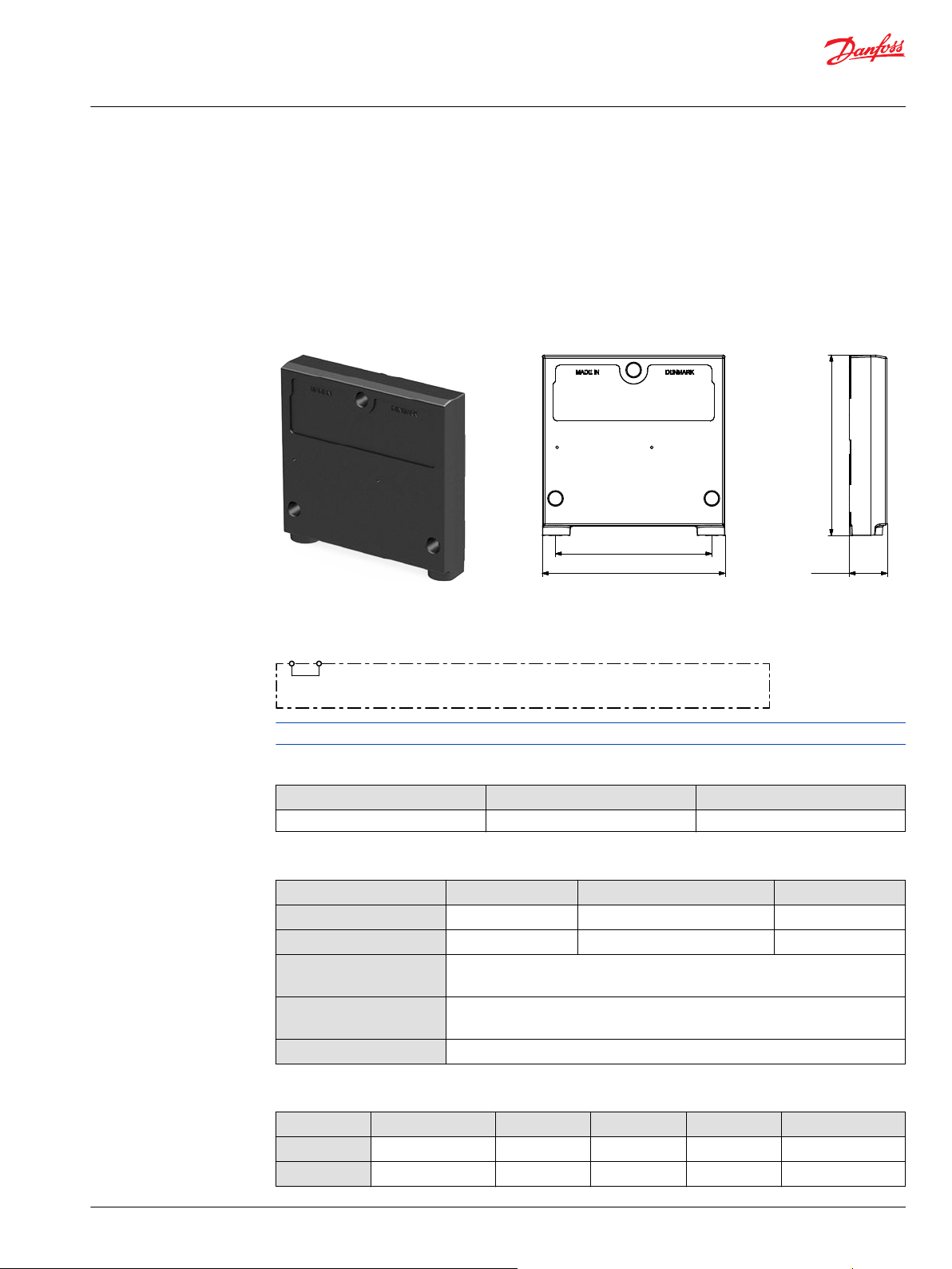
109.4 [4.31]
111 [4.37]
95 [3.74]
23 [0.91]
Technical Information
PVG 16 Proportional Valve Group
PVS End Plates
PVS/PVSI
The PVS/PVSI are made of either aluminum or cast iron material and works as an end plate.
The PVSI Start Plates features:
•
Integrated LS pressure relief to tank
•
Optional integrated thermal orifice
•
Optional version without seals
PVS/PVSI PVS/PVSI dimensions
Weight: 0.47 kg [1.05 lb]
PVS/PVSI schematic
See part number table for details on maximum pressure capacity
Technical specification for A/B-port
Max. continuous pressure Max. intermittent pressure Max. rated flow
380 bar [5510 psi] 420 bar [6090 psi] 65 l/min [17 US gal/min]
Technical specification
Parameter Minimum Recommended range Maximum
Fluid temperature
Fluid viscosity
Fluid cleanliness
(mechanical activation)
Fluid cleanliness
(PVE activation)
Operating temperature
-30°C [-22°F] 30 to 60°C [86 to 140°F] 90° [194°F]
4 mm2/s [39 SUS] 12 to 75 mm2/s [65 to 347 SUS] 460 mm2/s [2128 SUS]
23/19/16 (according to ISO 4406)
18/16/13 (according to ISO 4406)
Ambient: -30 to 60°C [-22 to 140°F]
Part numbers for PVS end plates
Part number Maximum pressure Material Weight kg [lb] Seals Mounting
157B2000
157B2020
©
Danfoss | July 2021 BC152986484323en-001104 | 89
300 bar [4351 psi] Aluminum 0.475 [1.05] Yes M8
300 bar [4351 psi] Aluminum 0.475 [1.05] Yes 5/16-18 UNC

Technical Information
PVG 16 Proportional Valve Group
PVS End Plates
Part numbers for PVS end plates (continued)
Part number Maximum pressure Material Weight kg [lb] Seals Mounting
157B2004
157B2014
350 bar [5076 psi] Cast iron 1.745 [3.85] Yes 5/16-18 UNC
350 bar [5076 psi] Cast iron 1.745 [3.85] Yes M8
90 | © Danfoss | July 2021 BC152986484323en-001104
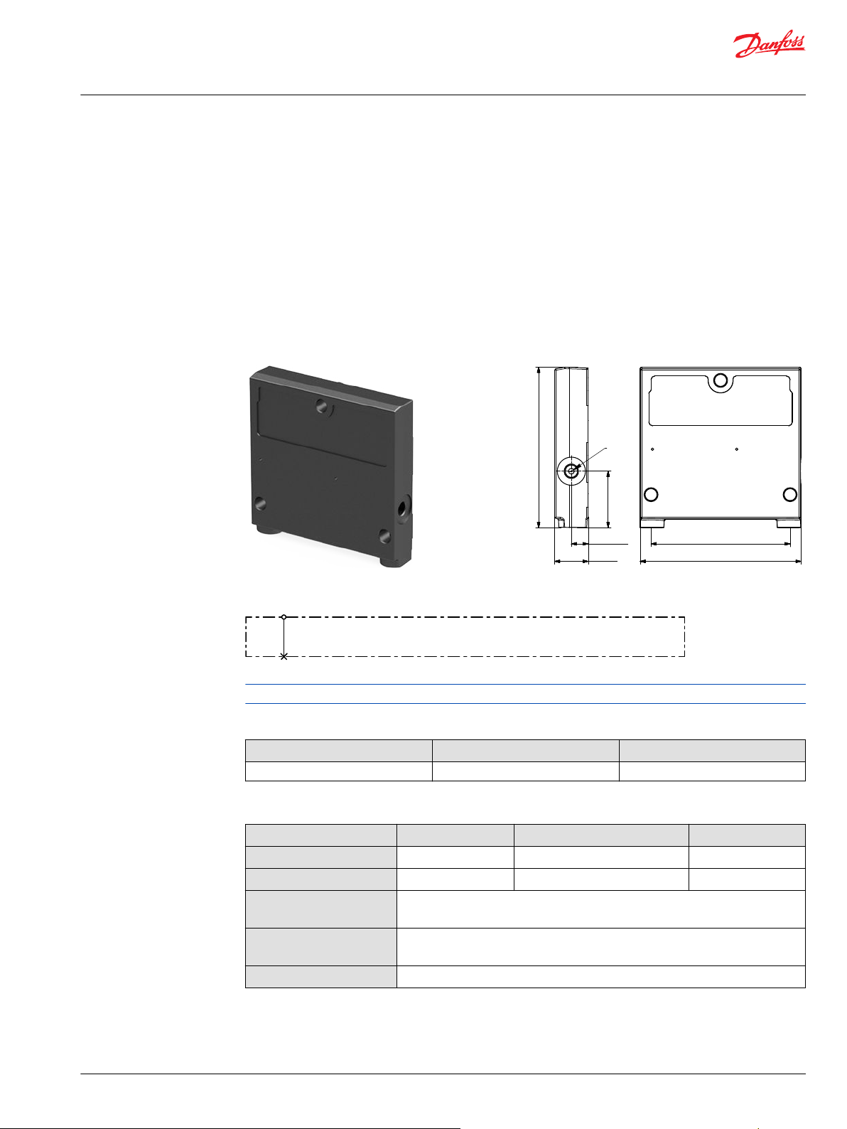
109.4 [4.31]
38.4 [1.51]
110 [4.33]
95 [3.74]
23 [0.9]
11.5 [0.45]
LX
G1/8
Lx
Technical Information
PVG 16 Proportional Valve Group
PVS End Plates
PVS/PVSI with LX-connection
The PVG 16 PVS end plates are placed at the end the valve stack section. Furthermore, the end plate is
ensuring Load Sense (LS) is relieved to tank pressure when the valve is not operated. The LX port enables
other remote valves to be connected onto the Load Sense shuttle network.
The PVS type end plates are made of aluminum while the PVSI types are made of cast iron thereby being
able to withstand a higher pressure.
The PVS/PVSI with LX-port connection features:
•
Integrated LS pressure relief to tank
•
Threaded LX port for connecting another valve to LS network
PVS/PVSI with LX-connection PVS/PVSI with LX-connection dimensions
PVS/PVSI with LX-connection schematic
See part number table for details on maximum pressure capacity
Technical specification for A/B-port
Max. continuous pressure Max. intermittent pressure Max. rated flow
380 bar [5510 psi] 420 bar [6090 psi] 65 l/min [17 US gal/min]
Technical specification
Parameter Minimum Recommended range Maximum
Fluid temperature
Fluid viscosity
Fluid cleanliness
(mechanical activation)
Fluid cleanliness
(PVE activation)
Operating temperature
-30°C [-22°F] 30 to 60°C [86 to 140°F] 90° [194°F]
4 mm2/s [39 SUS] 12 to 75 mm2/s [65 to 347 SUS] 460 mm2/s [2128 SUS]
23/19/16 (according to ISO 4406)
18/16/13 (according to ISO 4406)
Ambient: -30 to 60°C [-22 to 140°F]
©
Danfoss | July 2021 BC152986484323en-001104 | 91
Technical Information
PVG 16 Proportional Valve Group
PVS End Plates
Part numbers for PVS/PVSI with LX-port connection
Part number Max. pressure Material Weight kg [lb] LX port Mounting
157B2005
157B2015
157B2910
157B2011
157B2021
350 bar 5076 psi] Cast iron 1.695 [3.74]
300 bar [4351 psi] Aluminum 0.495 [1.09]
1/2-20 UNF 5/16-18 UNC
G1/4”
M12x1.5 ISO 6149
G1/8” M8
3/8-24 UNF 5/16-18 UNC
M8
92 | © Danfoss | July 2021 BC152986484323en-001104

77.4 [3.05]
11.5 [0.45]
70.8 [2.79]
35.2 [1.386]
35.3 [1.39]
30.5 [1.20]
20.4 [0.8]
109.4 [4.31]
40 [1.57]
112.7 [4.44]
95 [3.74]
23 [0.91]
T
Lx
M
P
Technical Information
PVG 16 Proportional Valve Group
PVS End Plates
PVSI with P-, T-, LX- and M-connection
PVSI is made of cast iron and works as an end plate. The PVSI with LX connection enables another valves
LS pressure to be shuttled to the pump when needed. The additional P- and T-port connections enables
an additional pump flow to a PVG 16 valve.
The PVSI with P-, T-, LX- and M-connection features:
•
Integrated LS pressure relief to tank
•
Threaded ports for P/T/LS/LX and M measuring gauge
PVSI with P-, T-, LX- and M-connection PVSI with P-, T-, LX- and M-connection dimensions
PVSI with P-, T-, LX- and M-connection schematic
Maximum pressure for P- and T-port
Max. P-port continuous Max. P-port intermittent Max. T-port static/dynamic
350 bar [5076 psi] 400 bar [5800 psi] 25/40 bar [365/580 psi]
See part number table for details on maximum pressure capacity
Technical specification for A/B-port
Max. continuous pressure Max. intermittent pressure Max. rated flow
380 bar [5510 psi] 420 bar [6090 psi] 65 l/min [17 US gal/min]
Technical specification
Parameter Minimum Recommended range Maximum
Fluid temperature
Fluid viscosity
Fluid cleanliness
(mechanical activation)
©
Danfoss | July 2021 BC152986484323en-001104 | 93
-30°C [-22°F] 30 to 60°C [86 to 140°F] 90° [194°F]
4 mm2/s [39 SUS] 12 to 75 mm2/s [65 to 347 SUS] 460 mm2/s [2128 SUS]
23/19/16 (according to ISO 4406)

Technical Information
PVG 16 Proportional Valve Group
PVS End Plates
Technical specification (continued)
Parameter Minimum Recommended range Maximum
Fluid cleanliness
(PVE activation)
Operating temperature
Part number for PVSI with P-, T-, LX-, M-ports
Part number P-port T-port LX-port M-port Mounting feet Weight
157B2920
18/16/13 (according to ISO 4406)
Ambient: -30 to 60°C [-22 to 140°F]
G3/8 G1/2 G1/8 G1/4 M8 0.47 kg [1.05 lb]
94 | © Danfoss | July 2021 BC152986484323en-001104

77.4 [3.05]
110 [4.33]
110 [4.33]
95 [3.74]
16
[0.63]
32 [1.26]
T
Technical Information
PVG 16 Proportional Valve Group
PVS End Plates
PVST with T-connection
The PVST end plate closes off the valve stack section placed between them by placing it at the end.
Furthermore, the end plate is ensuring Load Sense (LS) is relieved to tank pressure when the valve is not
operated.
The PVSI Start Plates features:
•
Integrated LS pressure relief to tank
•
Threaded T port
•
Optional integrated thermal orifice
PVST with T-connection PVST with T-connection dimensions
PVST with T-connection schematic
Maximum pressure for P- and T-port
Max. P-port continuous Max. P-port intermittent Max. T-port static/dynamic
350 bar [5076 psi] 400 bar [5800 psi] 25/40 bar [365/580 psi]
Technical specification for A/B-port
Max. continuous pressure Max. intermittent pressure Max. rated flow
380 bar [5510 psi] 420 bar [6090 psi] 65 l/min [17 US gal/min]
Technical specification
Parameter Minimum Recommended range Maximum
Fluid temperature
Fluid viscosity
Fluid cleanliness
(mechanical activation)
Fluid cleanliness
(PVE activation)
©
Danfoss | July 2021 BC152986484323en-001104 | 95
Operating temperature
When using a PVST with T-connection it is not possible to use the LS A/B fitting in the bottom of the PVG
section next to the PVST.
-30°C [-22°F] 30 to 60°C [86 to 140°F] 90° [194°F]
4 mm2/s [39 SUS] 12 to 75 mm2/s [65 to 347 SUS] 460 mm2/s [2128 SUS]
23/19/16 (according to ISO 4406)
18/16/13 (according to ISO 4406)
Ambient: -30 to 60°C [-22 to 140°F]

Technical Information
PVG 16 Proportional Valve Group
PVS End Plates
Part numbers for PVST with T-connection
Part number Material T-port Mounting feet Weight
157B2500
157B2520
Steel
G1/2 M8
7/8–14 5/16–18
0.47 kg [1.05 lb]
96 | © Danfoss | July 2021 BC152986484323en-001104

Technical Information
PVG 16 Proportional Valve Group
PVAS Stay Bolts
PVAS Stay Bolts kit for various PVG combinations consist of three tie rods, six washers, six nuts and O-ring.
Use the guide and reference tables how to choose PVAS kit.
The tie rods are inserted through the entire length of the PVG valve stack. The nuts are tightened at the
pump side and at the end plate.
To find the PVAS kit that fits your PVG 16 valve stack, you need to go to the table PVG 16 modules total
length and weight on page 98 and find the length. Then go to the table PVAS Part Numbers on page 98
and find the matching part number.
For stay bolts for a PVG 32/16 combination, see this PVG 32/16 Combinations on page 99.
Stay bolts for PVG 256/128/32/16 combinations consist of two different kits. See PVG 256/128/32/16
Combinations on page 100 to find the right kits for your combination.
Combinations with PVG 100 and PVG 120 requires special PVAS kits. These are not included in the PVAS
table.
©
Danfoss | July 2021 BC152986484323en-001104 | 97

Technical Information
PVG 16 Proportional Valve Group
PVAS Stay Bolts
PVAS Part Numbers
PVAS part numbers according to accumulated length interval PVG 16.
PVAS part numbers
Length, mm [in] Part number Length, mm [in] Part number
20 – 48 [0.79 – 1.89] 11188219 361 – 372 [14.21 – 14.65] 11188205
49 – 60 [1.93 – 2.36] 11188218 373 – 384 [14.69 – 15.12] 157B8026
61 – 72 [2.40 – 2.83] 157B8000 385 – 396 [15.16 – 15.59] 11188204
73 – 84 [2.87 – 3.31] 11188217 397 – 408 [15.63 – 16.06] 157B8007
85 – 96 [3.35 – 3.78] 157B8031 409 – 420 [16.10 – 16.54] 11188203
97 – 108 [3.82 – 4.25] 11188216 421 – 432 [16.58 – 17.01] 157B8027
109 – 120 [4.29 – 4.72] 157B8001 433 – 444 [17.05 – 17.48] 11188202
121 – 132 [4.76 – 5.20] 11188215 445 – 456 [17.52 – 17.95] 157B8008
133 – 144 [5.24 – 5.67] 157B8021 457 – 468 [17.99 – 18.43] 11188201
145 – 156 [5.71 – 6.14] 11188214 469 – 480 [18.47 – 18.90] 157B8028
157 – 168 [6.18 – 6.61] 157B8002 481 - 492 [18.94 – 19.37] 11188200
169 – 180 [6.65 – 7.09] 11188213 493 – 504 [19.41 – 19.84] 157B8009
181 – 192 [7.13 – 7.56] 157B8022 505 – 516 [19.88 – 20.31] 11188199
193 – 204 [7.60 – 8.03] 11188212 517 – 528 [20.35 – 20.79] 157B8029
205 – 216 [8.07 – 8.50] 157B8003 529 – 540 [20.83 – 21.26] 11188198
217 – 228 [8.54 – 8.98] 11188211 541 – 552 [21.30 – 21.73] 157B8010
229 – 240 [9.02 – 9.45] 157B8023 553 – 564 [21.77 - 22.20] 11188197
241 – 252 [9.49 – 9.92] 11188210 565 – 576 [22.24 – 22.68] 157B8030
253 – 264 [9.96 – 10.39] 157B8004 577 – 588 [22.72 – 23.15] 11188196
265 – 276 [10.43 – 10.87] 11188209 589 – 600 [23.19 – 23.62] 157B8061
277 – 288 [10.91 – 11.34] 157B8024 601 – 612 [23.66 – 24.09] 11188195
289 – 300 [11.38 – 11.81] 11188208 613 – 624 [24.13 – 24.57] 157B8081
301 – 312 [11.85 – 12.28] 157B8005 625 – 636 [24.61 – 25.04] 11188194
313 – 324 [12.32 – 12.76] 11188207 637 – 648 [25.08 – 25.51] 157B8062
325 – 336 [12.80 – 13.23] 157B8025 649 – 660 [25.55 – 25.98] 11188189
337 – 348 [13.27 – 13.70] 11188206 661 - 672 [26.02 – 26.46] 157B8082
349 – 360 [13.74 – 14.17] 157B8006
PVG 16 modules total length and weight
Table with total length of the PVG 16 depending on the number of PVB modules.
No. of
PVB 16
Length
mm [in]
Weight
kg [lb]
*
Weight is for a PVG 16 with a PVE on each working section and is only approximate.
1 2 3 4 5 6 7 8 9 10 11 12
111
151
191
*
[4.37]
7.2
[15.9]
[5.94]
10.9
[24]
[7.52]
14.6
[32.2]
231
[9.09]
18.3
[40.3]
271
[10.67]
22.0
[48.5]
311
[12.24]
25.7
[56.7]
351
[13.82]
29.4
[64.8]
391
[15.39]
33.1
[73]
431
[16.97]
36.8
[81.1]
471
[18.54]
40.5
[89.3]
511
[20.12]
44.2
[97.4]
551
[21.69]
47.9
[105.6]
98 | © Danfoss | July 2021 BC152986484323en-001104
Technical Information
PVG 16 Proportional Valve Group
PVAS Stay Bolts
PVG 32/16 Combinations
The table of PVB 32 and PVB 16 modules combination, the total length depending on the amount of
valve groups.
PVB 16
Modules in mm [in] 1 2 3 4 5 6 7 8 9 10 11
PVB 32
1
2
3
4
5
6
7
8
9
10
11
159
[6.26]
207
[8.15]
255
[10.04]
303
[11.93]
351
[13.82]
399
[15.71]
447
[17.60]
495
[19.49]
543
[21.38]
591
[23.27]
639
[25.16]
199
[7.83]
247
[9.72]
295
[11.61]
343
[13.50]
391
[15.39]
439
[17.28]
487
[19.17]
535
[21.06]
583
[22.95]
631
[24.84]
- - - - - - - - - -
239
[9.41]
287
[11.30]
335
[13.19]
383
[15.08]
431
[16.97]
479
[18.86]
527
[20.75]
575
[22.64]
623
[24.53]
671
[26.42]
279
[10.98]
327
[12.87]
375
[14.76]
423
[16.65]
471
[18.54]
519
[20.43]
567
[22.32]
615
[24.21]
663
[26.10]
- - - - - - - -
319
[12.56]
367
[14.45]
415
[16.34]
463
[18.23]
511
[20.12]
559
[22.01]
607
[23.90]
655
[25.79]
- - - - - - -
359
[14.13]
407
[16.02]
455
[17.91]
503
[19.80]
551
[21.69]
599
[23.58]
647
[25.47]
- - - - - -
399
[15.71]
447
[17.60]
495
[19.49]
543
[21.38]
591
[23.27]
639
[25.16]
- - - - -
439
[17.28]
487
[19.17]
535
[21.06]
583
[22.95]
631
[24.84]
- - - -
479
[18.86]
527
[20.74]
575
[22.64]
623
[24.53]
671
[26.42]
519
[20.43]
567
[22.32]
615
[24.21]
663
[26.10]
- -
559
[22.01]
607
[23.90]
655
[25.79]
-
©
Danfoss | July 2021 BC152986484323en-001104 | 99

C
Technical Information
PVG 16 Proportional Valve Group
PVAS Stay Bolts
PVG 256/128/32/16 Combinations
The tables of PVB 256/128, 32/16 modules, total length depending on the amount of valve groups.
Stay bolts for PVG 128/256/32/16 combinations consist of 2 different kits:
1. For PVAS containing 2 stay bolts – please look in the Table 1 below and use the part number before
the + symbol.
2. For PVAS containing 3 stay bolts – please look in Table 1 below and write down the length in
millimeters which is the number after the + symbol. Next you add the number from Table 2 below.
Now find the part number for the needed stay bolts in the table PVAS Part Numbers on page 98.
O-rings are a part of the PVAS kits – no additional part number needed.
Caution
It is not possible to do combinations exceeding 672 mm.
Example
For 2 PVB 256 and 1 PVB 128 and 1 PVB 32 and 2 PVB 16: PVAS 1 Part number = 11187681 from Table 1.
PVAS 2 = 278 mm from Table 1 + 152 mm from Table 2= 278+152 =430 mm which equals 157B8027 in
the PVAS table.
Table 2 – PVG 256/128 combinations
PVB 256
Modules (mm) 0 1 2 3 4 5 6 7
PVB 128
0 11187676+
1
2
3
4
5
6
7
8
9
40
11187320+
106
11187617+
172
11187655+
238
11187684+
304
11187658+
370
11187693+
436
11187705+
502
11187692+
568
11187710+
634
11187672+
126
11187677+
192
11187678+
258
11187679+
324
11187680+
390
11187699+
456
11187703+
522
11187694+
588
11187709+
654
11187673+
212
11187681+
278
11187682+
344
11187683+
410
11187696+
476
11187688+
542
11187704+
608
11187656+
298
11187658+
364
11187686+
430
11187705+
496
11187697+
562
11187710+
628
11187675+
384
11187685+
450
11187691+
516
11187694+
582
11187689+
648
11187696+
470
11187687+
536
11187704+
602
11187695+
668
11187697+
556
11187690+
622
11187698+
642
100 | © Danfoss | July 2021 BC152986484323en-001104
 Loading...