

Installation Guide
PVEO
PVH
G
tuator
of the electrical actuator is recommended.
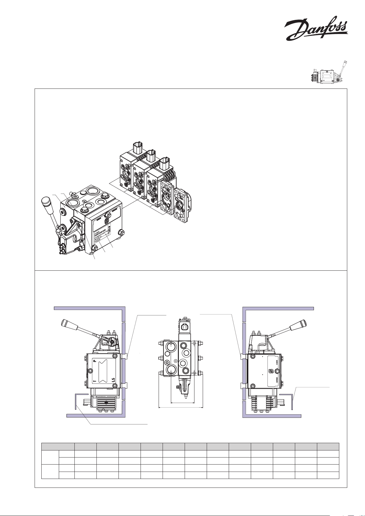
Proportional Valve Group
PVG 16
Identikation, Identication
Standardmontage: PVP til venstre for PVM
Standard installation: PVP to the left of PVM
Normale Montage: PVP links von PVM
Montage standard: PVP à gauche de PVM
PVP
F
E
PVM
PVB
D
PVS
C
PVEA
PVEA-F
PVMD
V310395.B
V3104 00A
C: PVG-nummer, uge og år for montage og serienummer
D: PVP-trykindstilling
E: PVP-nummer, uge og år for fremstilling og serienummer
F: PVB - A-port, nummer, uge og år for fremstilling og serienummer
G: PVM, uge og år for fremstilling
C: PVG-number, week and year of installation and series number
D: PVP - pressure setting
E: PVP-number, week and year of manufacturing and series
number
F: PVB - A-port, number, week and year of manufacturing and
series number
G: PVM, week and year for manufacturing
C: PVG-Nummer, Woche und Jahr der Montage und Seriennummer
D: PVP - Druckeinstellung
E: PVP-Nummer, Woche und Jahr der Herstellung und
Seriennummer
F: PVB - A-Anschluß, Nummer, Woche und Jahr der Herstellung
und Seriennummer
G: PVM, Woche und Jahr der Herstellung
C: PVG-numéro, semaine et année de montage et numéro sériel
D: PVP - réglage de pression
E: PVP-numéro, semaine et année de fabrication et numéro sériel
F: PVB - orice-A, numéro, semaine et année de fabrication et
numéro sériel
G: Semaine et année de fabrication
Montering og orientering af stik
Installation and plug orientation
Montage und Ausrichtung des Steckers
Montage et orientation de la prise
L1
Mounting thread:
M8 x min 10 mm or
5/16-18 x min 0,39 in
Torque:
P VS: 20 N•m [177 lbf•in]
PVSI: 40 N•m [354 lbf•in]
In particularly exposed
applications, protection
in the form of screening
of the electrical ac
is recommended.
Mounting thread:
M8 x min 10 mm or
5/16-18 x min 0,39 in
Torque:
40 N•m [354 lbf•in]
L2
In particularly exposed applications,
protection in the form of screening
No. of PVB 16 1 2 3 4 5 6 7 8 9 10 11 12
mm 74 114 154 194 234 274 314 354 394 434 474 514
L1
[in] [2.91] [4.49] [6.06] [7.64] [9. 21] [10.79] [12 .36] [13.94] [15.51] [17.09 ] [18.66] [20.24]
mm 140 189 213 262 311 336 385 434 458 507 551 576
L2
[in] [5. 51] [7.4 4] [8.39] [10.31] [12 .24] [13.2 3] [15.16] [17. 09] [18.03] [19.9 6] [21.69] j
V310 401.B
© Danfoss, 2015-08 L1216888 • Rev BD • Aug 2015 1
V310183.A
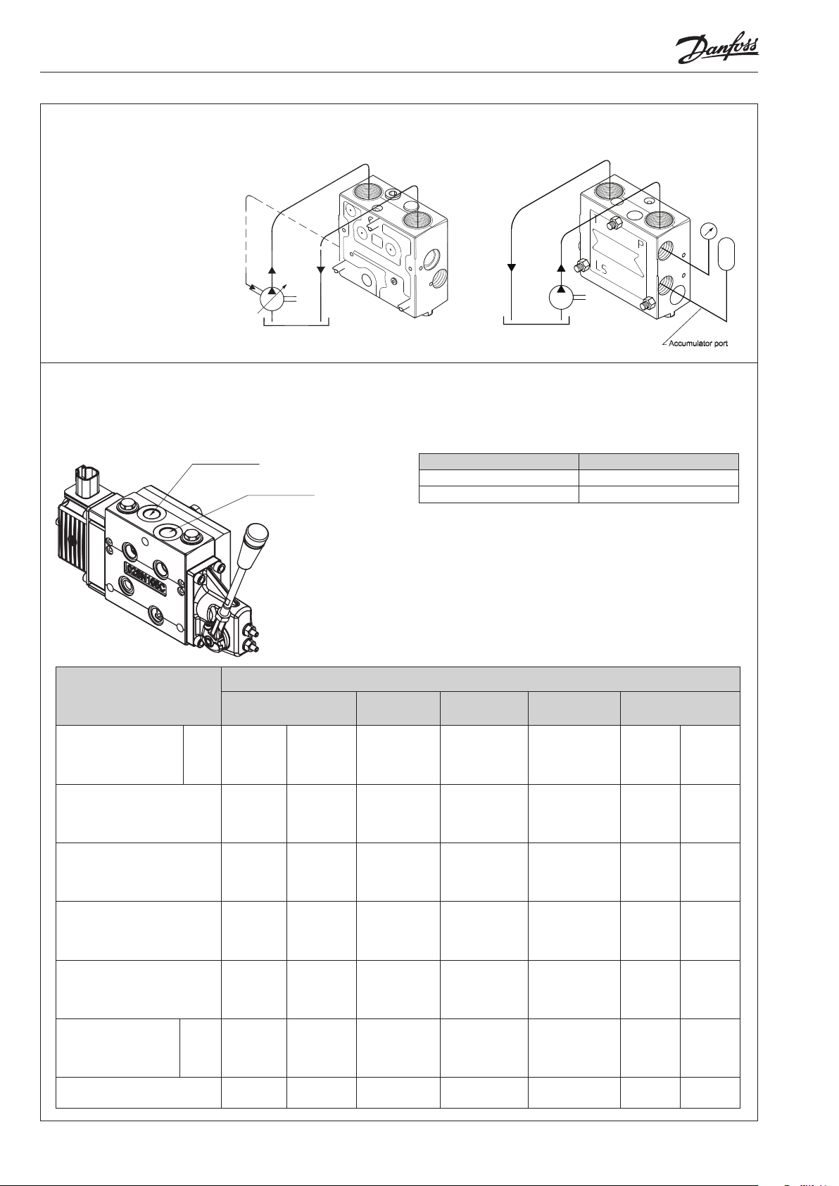
Tilslutning, pumpesidemodul, PVP
Work port B or:
Connection, pump side module, PVP
Anschluß, pumpenseitiges Modul, PVP
Raccordement, plaque d’entrée PVP
157- 81.13
Tilslutning, grundmodul, PVB
Connection, basic module, PVB
Anschluß, Grundmodul, PVB
Raccordement, module de distribution, PVB
G or in -16
Work port B or:
G or in -16
V3103 96.B
Max. tilspændingsmoment
Max. tightening torque
Max. Anzugsmoment
Couple de serrage maxi
Forskruning
Screwed connection
Verschraubung
Raccord
Med stålskive
With steel washer
Stahldichtring
Avec rondelle en acier
Med kobberskive
With copper washer
Kupfer Dichtring
Avec rondelle en cuivre
Med aluminiumsskive
With aluminium washer
Aluminium Dichtring
Avec rondelle en all
Med skærekant
With cutting edge
Mit Dichtkante
Tranchant
Forskruning
Screwed connection
Verschraubung
Raccord
O-ring
RG
BSP. F
R
G
UNF 7/8 in - 14 1 1/16 in - 12 3/4 in - 16 1 1/16 in - 12 1/2 in - 20 3/8 in - 24 1/2 in - 20
1/2 in 3/4 in 3/8 in 3/4 in 1/4 in 1/8 in 1/4 in
130 N• m
[1150 lbf•in]
30 N•m
[270 lbf•in]
70 N•m
[620 lbf•in]
130 N• m
[1150 lbf•in]
90 N•m
[800 lbf•in]
P A/B T
[1850 lbf•in]
[1850 lbf•in]
[1060 lbf•in]
210 N•m
50 N•m
[445 lbf•in]
110 N• m
[970 lbf•in]
210 N•m
120 N•m
Nominel tryk
Rated pressure
Nomineller Druck
Pression nominale
Product Rated pressure
with PVS 300 bar [4351 psi]
with PVSI 350 bar [5076 psi]
Tilslutning • Connection • Anschluss • Reccordement
LS, M, LSA, LSB
PVH, Accu.
130 N• m
[1150 lbf•in]
30 N•m
[270 lbf•in]
70 N•m
[620 lbf•in]
130 N• m
[1150 lbf•in]
90 N•m
[800 lbf•in]
210 N•m
[1850 lbf•in]
50 N•m
[445 lbf•in]
110 N• m
[970 lbf•in]
210 N•m
[1850 lbf•in]
120 N•m
[1060 lbf•in]
40 N•m
[350 lbf•in]
20 N•m
[180 lbf•in]
30 N•m
[270 lbf•in]
40 N•m
[350 lbf•in]
30 N•m
[270 lbf•in]
LX
PVS PVSI
17 N •m
[150 lbf•in]
15 N •m
[135 lbf•in]
15 N •m
[135 lbf•in]
17 N •m
[150 lbf•in]
10 N•m
[90 lbf•in]
40 N•m
[350 lbf•in]
20 N•m
[180 lbf•in]
30 N•m
[270 lbf•in]
40 N•m
[350 lbf•in]
30 N•m
[270 lbf•in]
2 L1216888 • Rev BD • Aug 2015 © Danfoss, 2015-08

Mekanisk justering af max ow
B
4 [0.16]
V310 397.B
V310 397.B
Mechanical adjustment of max ow
Mechanische Einstellung des maximalen Volumenstroms
Ajustement mécanique du débit maximum
Trykindstilling PVP
Pressure setting PVP
Druckeinstellung PVP
Réglage de pression PVP
10 [0.40]
6 ±1 N•m
[53 ±9 lbf•in]
3 [0.12]
V3 103 67.A
Relief valve 1 x x
Relief valve 2 x x
Montage af PVE
Installation of PVE
Montage von PVE
Installation de PVE
6 [0.24]
360o≈120 bar
[1740 psi]
360o≈100 bar
[1450 psi]
Relief valve 2 Relief valve 1
Before week 40/2003 Week 40/2003 - week 2/2012 After week 2/2012
V310 402. B
V310402.
© Danfoss, 2015-08 L1216888 • Rev BD • Aug 2015 3

Standard mounting
t P -> B limit
t
P
Oliestrømmens retning og indstilling
af max. olietrøm. PVP til venstre for
PVM.
Oil ow direction and setting of max.
ow. PVP to the left of PVM.
->A
A-port
B-port
Richtung des Ölstroms und
Einstellung des max. Ölstroms. PVP
links von PVM.
Sens du débit et réglage de débit
maxi. PVP à gauche de PVM.
Connections
Pin layout: PVEO
The PVEO is available for simple ON/OFF actuation
of the main spool. It has a 4 pin Deutsch
connector.
Pin layout: PVEA
The PVEA is available as the PVE for proportional
control of the spool. It has a 4 pin Deutsch
connector.
Pin layout: PVEA-F
The PVEA-F is available for oat options.
It has a 6 pin Deutsch connector where the oat
command has a dedicated pin.
All features in the PVEA is also in the PVEA-F.
WWarning
When PVEA-F is given oat command it will actuate
the spool into oat state no matter what position in
spool has or set point given to PVEA-F.
PVEA PVEO
4
PVEA-F
6
5
1
1. Vi (signal pin)
2. Sp (spool position)
23
3. Vneg (÷)
4. Vbat (+)
V3103 58.A
1. Vi (signal pin)
2. NC (not connected)
1
3. Vf (oat)
4. Sp (spool position)
2
5. Vneg (÷)
34
6. Vbat (+)
V3103 59.A
4
Function
Neutral 0 0
Q: P→ A U
Q: P→ B 0 U
Function Signal voltage (US)
Neutral US (p in 1) = 0.5 • U
Q: P→ A US (pin 1) = (0.5→0.25) • U
Q: P→ B US (pin 1) = (0.5→0.75) • U
P->A
B-por
A-port P -> A limi
1
1. NC 2 (A-direction)
2. Vneg (÷)
23
3. Vneg (÷)
4. NC 4 (B-direction)
V3103 58.A
Signal voltage
A (pin 1) B (pin 2)
DC
V3103 94.B
V310394.B
0
DC
DC
DC
DC
Udluftning
Hvis gruppen er monteret vertikalt, anbefales det at udlufte ved justerskruer (Pos. A).
Bemærk: Ved PVEA kan det, pga.dens hydrauliske opbygning, være påkrævet at
A
foretage udluftning.
Bleeding
If the group is installed vertically, it is recommended to bleed it at the adjusting
screws (Pos. A).
Note: Because of the hydraulic build-up of PVEA, it may be necessary to bleed the
PVEK.
Entlüftung
Wenn die Gruppe vertikal montiert ist, empfehlen wir an den Justierschrauben zu
entlüften (Pos. A).
Beachte: Wegen des hydraulischen Aufbaus von PVEA kann eine Entlüftung
erforderlich sein.
Purge
Si l'ensemble est monté verticalement, il est recommandé de le purger au moyen des
vis d'ajustage (Pos. A).
Nb! En raison du système hydraulique des PVEAs il peut s'avérer nécessaire de purger.
4 L1216888 • Rev BD • Aug 2015 © Danfoss, 2015-08
V310399. B
 Loading...