

Page 1
Technical Information
PVG 128/256
Proportional Valve Group
www.danfoss.com
Page 2

Technical Information
PVG 128/256 Technical Information
Revision history Table of revisions
Date Changed Rev
July 2021 Corrected PVB 256 3-way Compensator with LS A/B parts table 0510
March 2021 Corrected PVSI with P and T port dimensions 0509
May 2020 Minor revision - data corrections throughout, updated version number to match online
catalogue.
Changed document number from 'BC00000380' to 'BC220686485279' XX
June 2019 Minor changes throughout document, new images added. 0407
September 2018 Safety topic added. 0406
August 2018 Layout changes, minor edits 0405
June 2018 Table for dimensions page 90 update. 0404
March 2018 Minor edits 0403
January 2018 correction to part number pg 54 0402
October 2017 Updated port names on schematics 0401
July 2017 Updated specs and dimensions 0301
March 2017 Corrected PVAS equation 0203
March 2017 Updated PVAS tables 0202
January 2017 Changed PVEO and PVEH product data 0201
November 2016 First edition 0101
0508
2 | © Danfoss | July 2021 BC220686485279en-000510
Page 3

Technical Information
PVG 128/256 Technical Information
Contents
General Information
Safety in Systems..............................................................................................................................................................................5
PVG 128/256 Proportional Valve Group...................................................................................................................................7
PVG general description................................................................................................................................................................ 8
Features of the PVG 128/256 valve............................................................................................................................................ 8
PVPV Inlet Modules
Closed Center PPRV for PVE Activation and/or Mechanical........................................................................................... 10
PPRV for PVH/PVHC Activation and/or Mechanical ..........................................................................................................12
PVB 128 Variant Overview
PVB 128 3-way Compensator.................................................................................................................................................... 15
PVB 128 3-way Compensator with LS A/B.............................................................................................................................18
PVB 128 3-way Compensator with LS A/B and PVLP.........................................................................................................22
PVB 256 Variant Overview
PVB 256 3-way Compensator.................................................................................................................................................... 28
PVB 256 3-way Compensator with LS A/B.............................................................................................................................32
PVB 256 3-way Compensator with LSA/B and PVLP..........................................................................................................36
PVB 256 3-way Compensator with LS A/B, PVLP and Turbo...........................................................................................41
PVLP Shock and PVLA Suction Valves
PVLP Overview................................................................................................................................................................................46
PVLP Technical Data......................................................................................................................................................................46
PVBS Main Spool
PVBS Main Spools variant overview........................................................................................................................................49
Flow control spools..................................................................................................................................................................49
PVBS main spools product details........................................................................................................................................... 49
PVS Main spools part numbers................................................................................................................................................. 51
Flow control spools..................................................................................................................................................................52
Flow control spool closed neutral position............................................................................................................... 52
Flow control spool throttled open neutral position...............................................................................................52
Single acting cylinder flow control spool closed neutral position, flow control B port............................ 53
Flow control spool closed neutral position with A-float.......................................................................................54
PVM Manual Activation
PVM Technical Data.......................................................................................................................................................................56
PVH Hydraulic Actuation
PVH Technical Data....................................................................................................................................................................... 58
PVHC Electro-Hydraulic Actuator type
PVHC Technical Data.....................................................................................................................................................................60
PVMD Cover Manual Actuation Only
PVMD Part Numbers..................................................................................................................................................................... 61
PVE Electrical Actuator
PVE Series 7 Electrical Actuator.................................................................................................................................................62
PVE Variant Overview
PVE Variant Overview................................................................................................................................................................... 64
PVEO................................................................................................................................................................................................... 64
PVEO..............................................................................................................................................................................................65
PVEO Schematics and Dimensions............................................................................................................................... 66
PVEO Technical Data..........................................................................................................................................................66
PVEO 128/256 Reaction Times........................................................................................................................................67
PVEO Variants for PVG....................................................................................................................................................... 67
PVEH....................................................................................................................................................................................................68
PVEH Overview..........................................................................................................................................................................68
PVEH Schematics and Dimensions............................................................................................................................... 69
PVEH Technical Data.......................................................................................................................................................... 69
PVEH Reaction Times......................................................................................................................................................... 71
©
Danfoss | July 2021 BC220686485279en-000510 | 3
Page 4

Technical Information
PVG 128/256 Technical Information
Contents
PVEH Hysteresis and Ripple.............................................................................................................................................71
PVEH Variants for PVG....................................................................................................................................................... 72
Connector Overview
Connector Overview.....................................................................................................................................................................73
Fault Monitoring and Reaction
Generic Fault Reaction.................................................................................................................................................................74
PVEH Fault Reaction Overview..................................................................................................................................................75
Functionality Overview
Standard and Fixed US 0-10 Vdc.............................................................................................................................................. 76
PWM Voltage Control..............................................................................................................................................................76
Float A-Port (-FLA)..........................................................................................................................................................................78
PVE Power Save.............................................................................................................................................................................. 78
Special Features
Dedicated Float Pin (UF)..............................................................................................................................................................79
Disable Mode...................................................................................................................................................................................79
Performance Overview
PVG 128/256 Reaction Times.....................................................................................................................................................80
Hysteresis and Ripple................................................................................................................................................................... 81
Oil Consumption............................................................................................................................................................................ 81
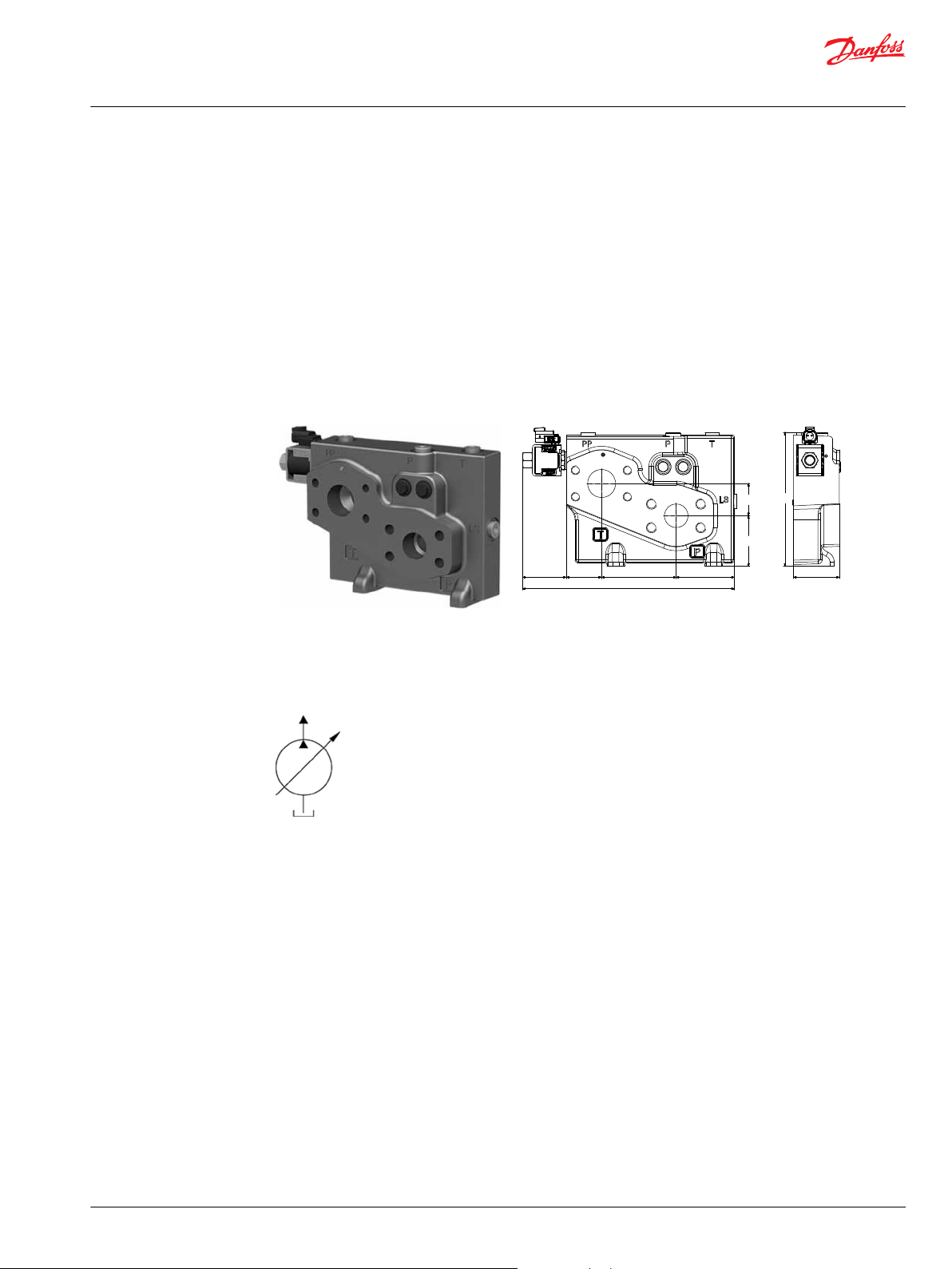
PVSI/PVGI End and Interface Plates
PVSI with or without LX-connection.......................................................................................................................................83
PVSI with P and T port connections........................................................................................................................................ 84
PVGI Interface Plate.......................................................................................................................................................................85
PVAS
PVAS for Combo............................................................................................................................................................................. 87
PVAS Part Number Overview.....................................................................................................................................................88
PVG Valve Schematics
Valve Schematics............................................................................................................................................................................90
Dimension Overview
Dimension Overview for PVG 128/256...................................................................................................................................92
Specifications example................................................................................................................................................................ 95
4 | © Danfoss | July 2021 BC220686485279en-000510
Page 5
W
Technical Information
PVG 128/256 Technical Information
General Information
Safety in Systems
All types and brands of control valves, including proportional valves, can fail. Therefore, the necessary
protection against the serious consequences of a functional failure should always be built into the
system.
General safety considerations
For each application an assessment should be made for the consequences of the system in case of
pressure failure and uncontrolled or blocked movements.
Warning
Because the proportional valve is used in many different applications and under different operating
conditions, it is the sole responsibility of the manufacturer to ensure that all performance, safety and
warning requirements of the application is met in his selection of products and complies with relevant
machine specific and generic standards.
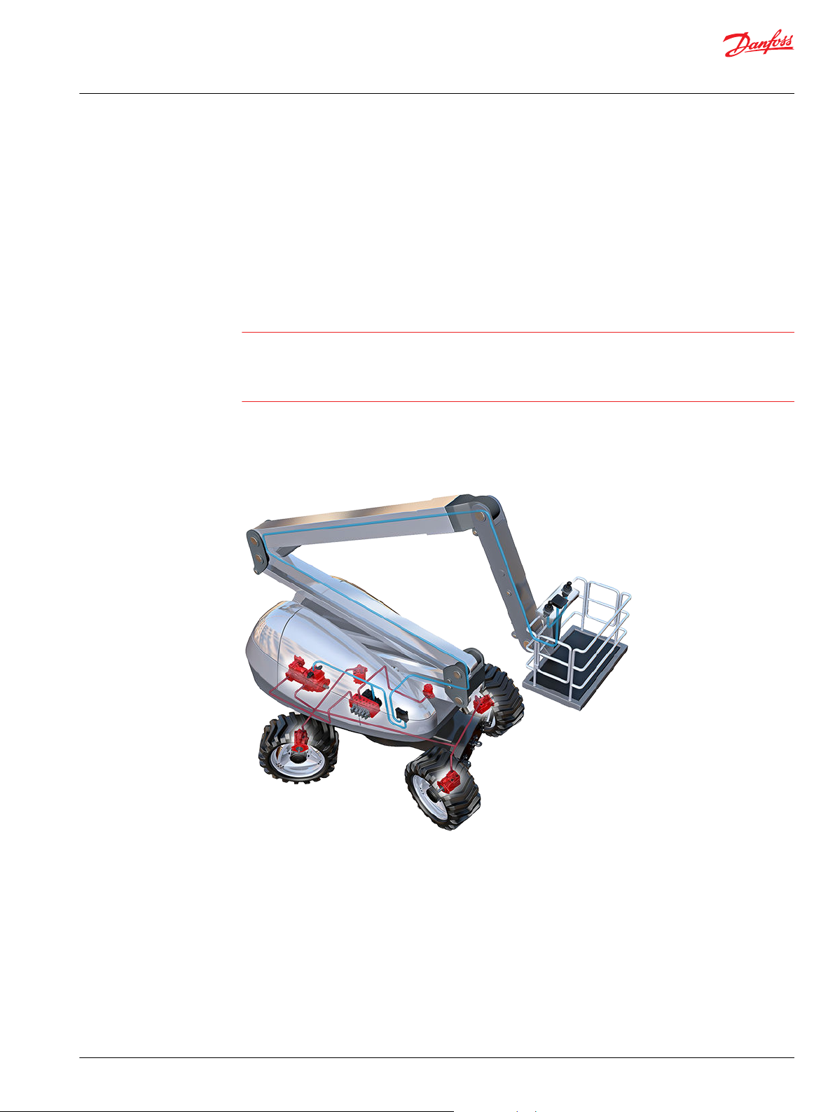
Control system example
An example of a control system using an aerial lift is shown below:
Aerial lift
This example breaks down the control system into smaller bits explaining the architecture in depth. Even
though many Danfoss components are used in the PVG control system.
The function of the control system is to use the output from the PVE together other external sensors to
ensure the PLUS+1 main controllers correct function of the aerial lift.
©
Danfoss | July 2021 BC220686485279en-000510 | 5
Page 6
W
C
Technical Information
PVG 128/256 Technical Information
General Information
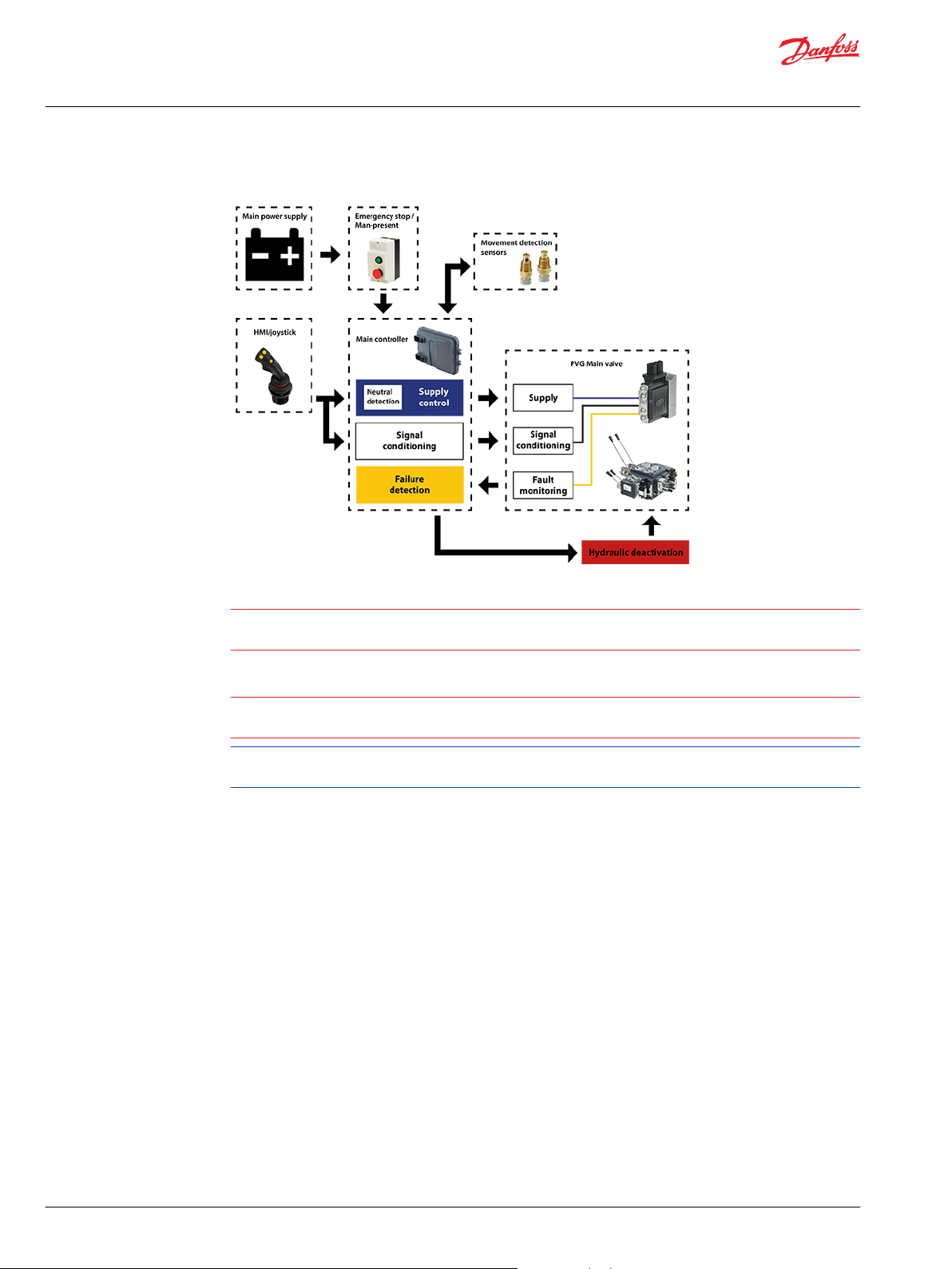
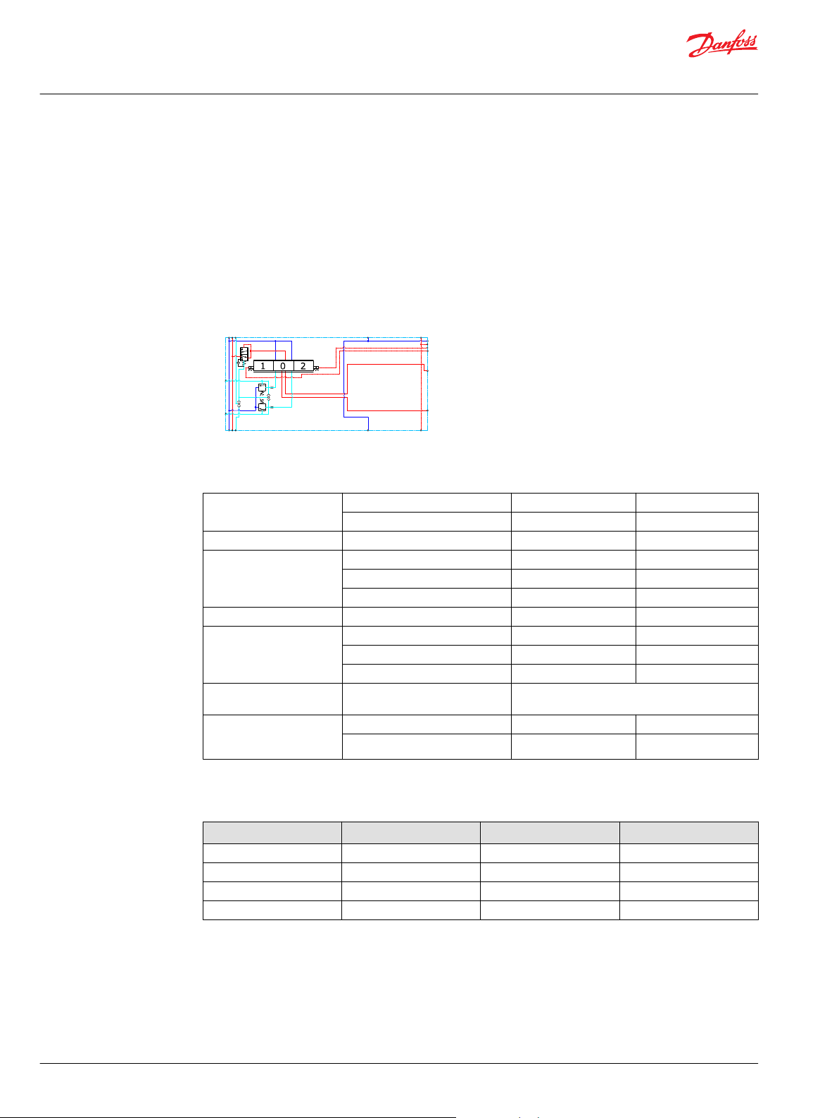
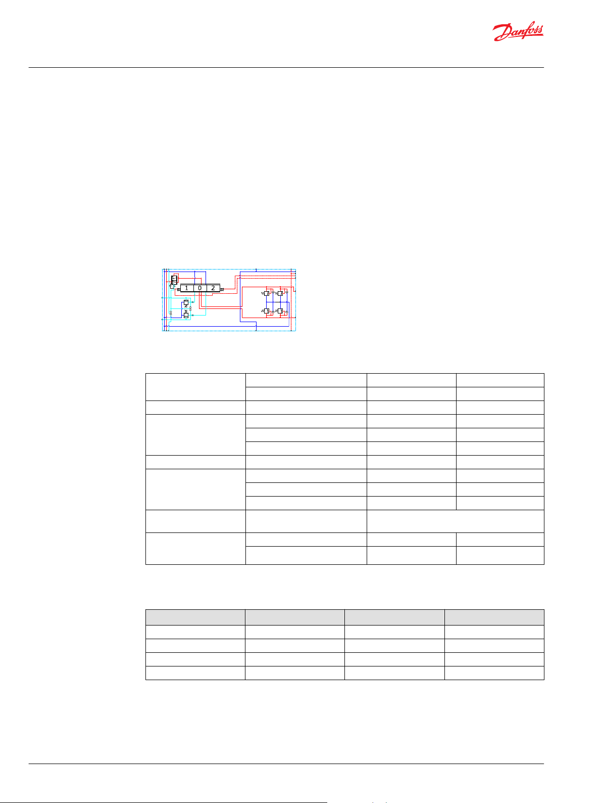
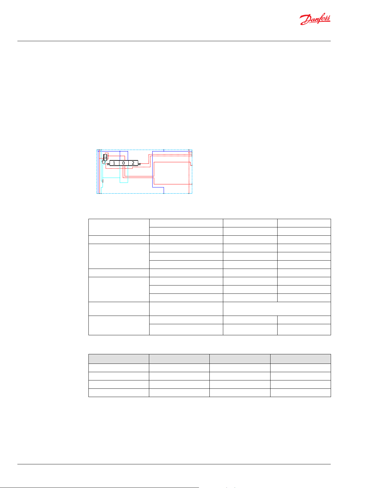
Electrical block diagram
Warning
It is the responsibility of the equipment manufacturer that the control system incorporated in the
machine is declared as being in conformity with the relevant machine directives.
Caution
A mix of electrical actuation and hydraulic actuation on the same valve stack is not safe. PVE and PVH are
designed for different pilot pressure.
Cost-free repairs, as mentioned in Danfoss General Conditions of Sale, are carried out only at Danfoss or
at service shops authorized by Danfoss.
6 | © Danfoss | July 2021 BC220686485279en-000510
Page 7
PVPV
PVE/PVHC ActuatorsPVB 256
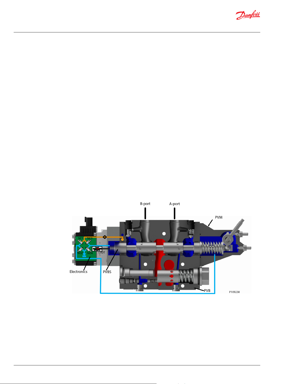
PVM PVBS
PVB 128
PVMD/PVH Covers
PVSI/PVGI
PVAS
P109160
Technical Information
PVG 128/256 Technical Information
General Information
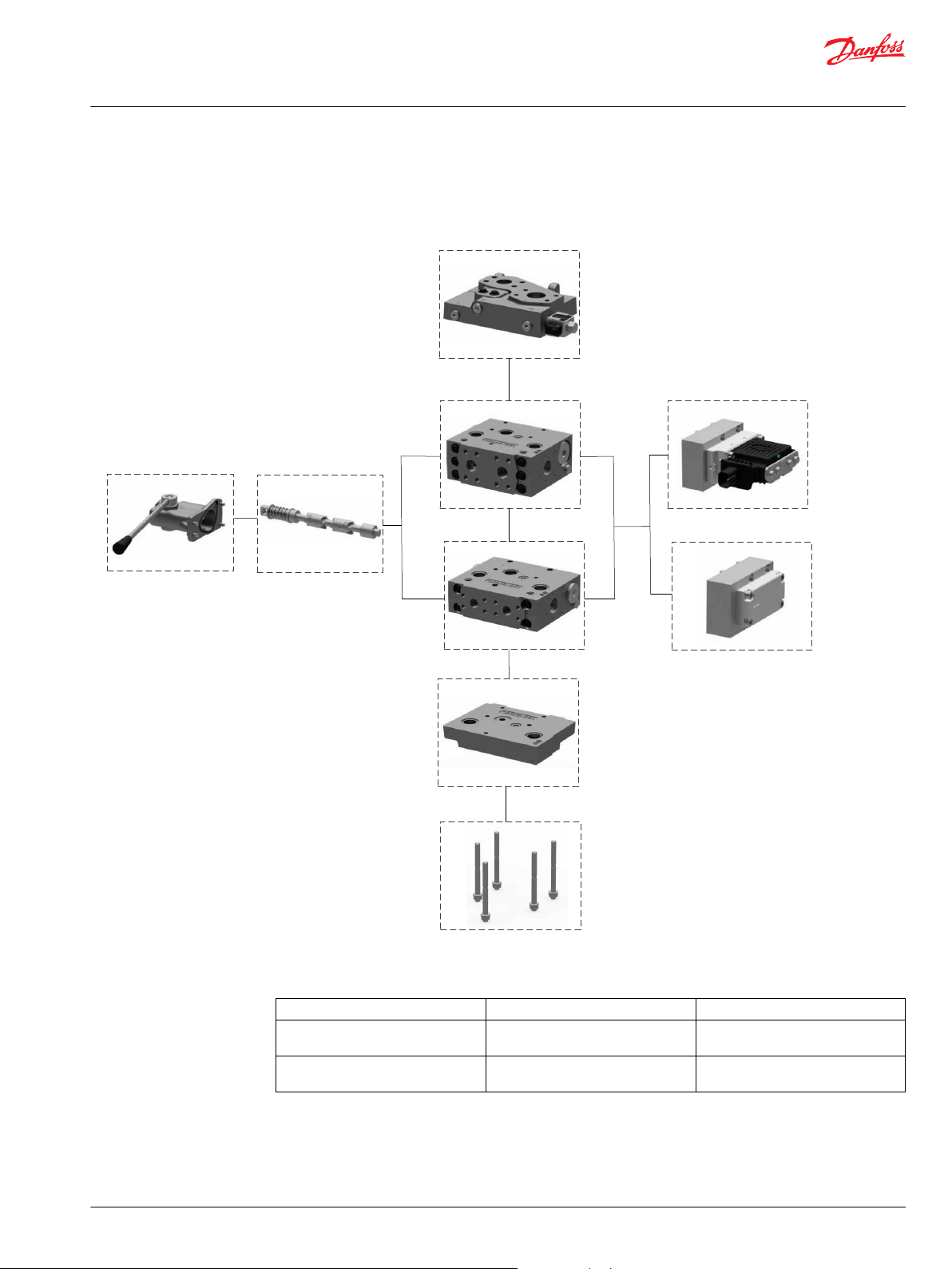
PVG 128/256 Proportional Valve Group
Navigation
PVPV PVB 256 PVB 128
PVBS Main Spool on page 49 PVM PVE Series 7 Electrical Actuator on
PVMD/PVH Covers PVSI/PVGI End and Interface Plates on
page 82
page 62/PVHC
PVAS
©
Danfoss | July 2021 BC220686485279en-000510 | 7
Page 8
Technical Information
PVG 128/256 Technical Information
General Information
PVG general description
PVG is a hydraulic, load-sensing proportional valve, designed for optimal machine performance and
maximum design flexibility.
The PVG valve design is based on a modular concept that enables machine designers to specify a valve
solution suitable for multiple market segments across multiple applications.
The load independent proportional control valve and high performance actuator technology combined
with a low pressure drop design improves the machine performance and efficiency – increasing
productivity and reducing energy consumption.
Features of the PVG 128/256 valve
•
Inlet flow up to 1200 l/min [317 US gal/min]
•
Compact sectional platform solution for easy integration with PVG 16 and PVG 32
•
Load-independent flow control:
Oil flow to an individual function is independent of the load pressure of this function
‒
Oil flow to one function is independent of the load pressure of other functions
‒
•
Reliable regulation characteristics across the entire flow range
•
Load sense relief valves for A and B port enables reduced energy loss at target pressure
•
Optimized for lower pressure drop and higher efficiency
•
Several options for connection threads and flange mount
•
Compact design, easy installation and serviceability
•
Static Load sense system when selecting pump control
•
Internal T0 connection in all PVSI/PVGI
8 | © Danfoss | July 2021 BC220686485279en-000510
Page 9
59
47.5
285.5
100.5
78.5
68
43.5
180.6
62
PVPV 256
PVPV inlet module dimensions (mm)
Weight 10 kg [22 lbs]
Technical Information
PVG 128/256 Technical Information
PVPV Inlet Modules
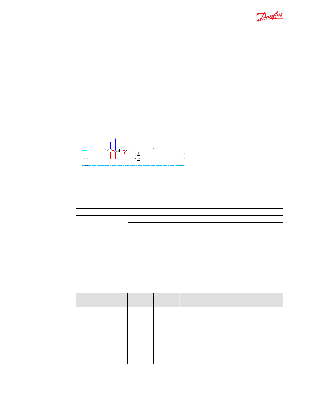
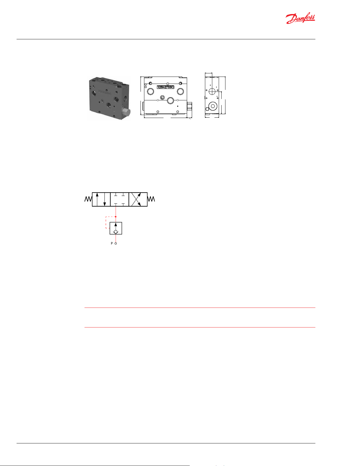
The Closed Center PVPV inlet with integrated pilot pressure reduction valve (PPRV) for PVE activation is
intended for use with variable displacement pumps in applications where a valve group with electrohydraulic or hydraulically controlled work sections is desired.
All Variants are prepared for 2xPVLP shock/anti-cavitation valves for pressure peak protection and anticavitation prevention.
PVLPs are for pressure peak protection in the system and pump.
Optional electrically actuated pilot shut off valve PVPP provides additional functional system safety by
removing pilot oil from the electrical actuation or hydraulic actuation system, disabling main spool
actuation.
All variants have internal T0 to tank connection in the PVSI and PVGI end plates.
The PVPV 256 inlet module variants are based on a generic platform with a selection of additional
features, enabling you to tailor the PVPV inlet to suit the demands of any hydraulic system.
Variable displacement pump symbol
The generic PVPV 256 inlet module platform includes the following main variants:
Closed Center PVPV with PPRV PVEClosed center inlet module for variable displacement pumps.
Closed Center PVPV with PPRV for PVH/PVHC Closed center inlet module for variable displacement pumps.
Optional feature: PVPP Electrical Pilot Shut-Off Valve - Closed center inlet module for variable
displacement pumps.
©
Danfoss | July 2021 BC220686485279en-000510 | 9
Page 10
P
Pp
T
T
LS
P
P109162
Technical Information
PVG 128/256 Technical Information
PVPV Inlet Modules
Closed Center PPRV for PVE Activation and/or Mechanical
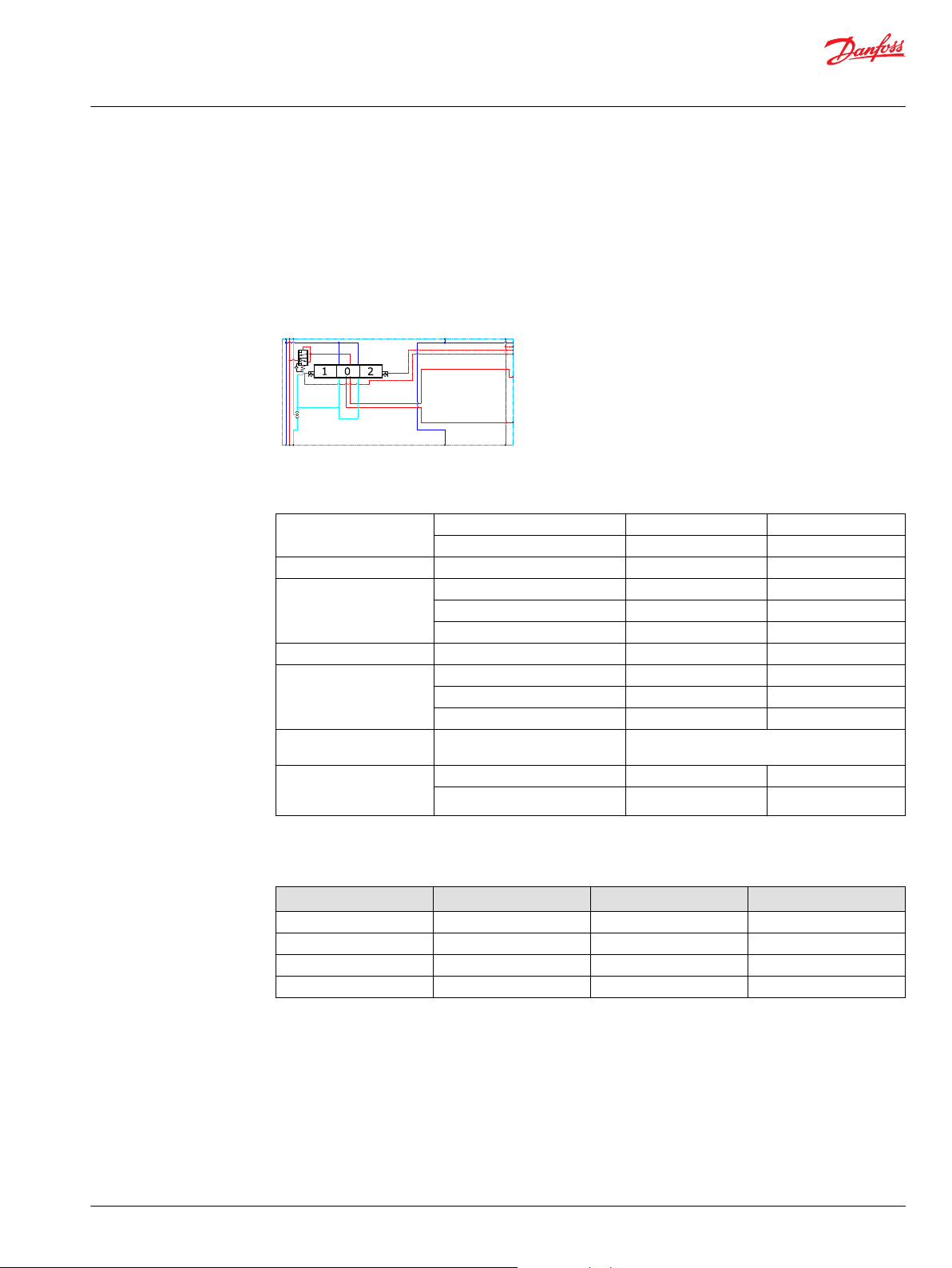
The PVPV 256 inlet modules, also referred to as pump side modules, act as an interface between the PVG
128/256 proportional valve group and the hydraulic pump and tank reservoir.
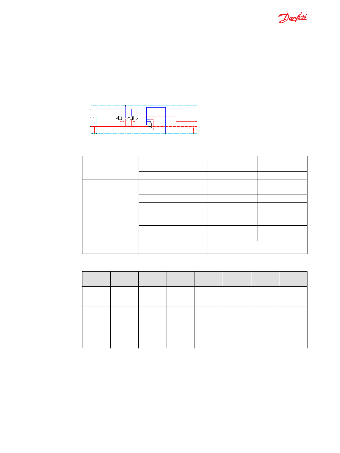
Schematic
Technical data
Max. rated pressure P-port continuous 350 bar [5076 psi]
P-port intermittent 400 bar [5800 psi]
T-port static/dynamic 25/40 bar [363/580 psi]
Rated Port P (PVPV/PVSI) P-port 600/600 l/min [159/159 US gal/min]
Oil temperature Recommended 30 to 60°C [86 to 140°F]
Minimum -30°C [-22°F]
Maximum 90° [194°F]
Ambient temperature Recommended -30 to 60°C [-22 to 140°F]
Oil viscosity Operating range 12 to 75 mm2/s [65 to 347 SUS]
Minimum 4 mm2/s [39 SUS]
Maximum 460 mm2/s [2128 SUS]
Oil contamination
according to ISO 4406
Maximum 23/19/16
Part numbers for Closed Center PVPV with PPRV for PVE
Part
number
11173130 PVE
11176703 PVE
11176691 PVE
11176702 PVE
10 | © Danfoss | July 2021 BC220686485279en-000510
PPRV P-port T-port
Metric
Flange
1-1/4”
Thread Ports
G1-1/2" BSP
SAE Flange
1-1/4” UNF
Thread Ports
1-7/8” UNF
Metric
Flange
1-1/2”
Thread Ports
G1-1/2" BSP
SAE Flange
1-1/2” UNF
Thread Ports
1-7/8” UNF
LS-port
Gauge-port
G3/8"BSP G3/8"BSP G1/4"BSP M12
G3/8"BSP G3/8"BSP G1/4"BSP M12
9/16-18 UNF 3/4-16 UNF 7/16-20 UNF M12
9/16-18 UNF 3/4-16 UNF 7/16-20 UNF M12
M-port
Gauge-port
T- and Pp
Gauge-port
Mounting
feet
Page 11
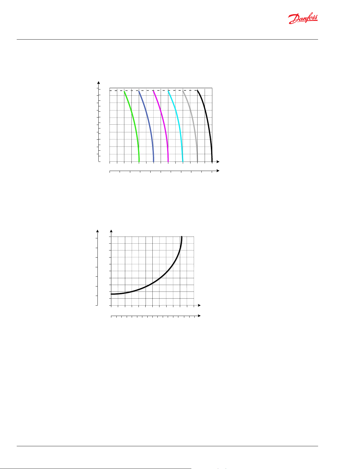
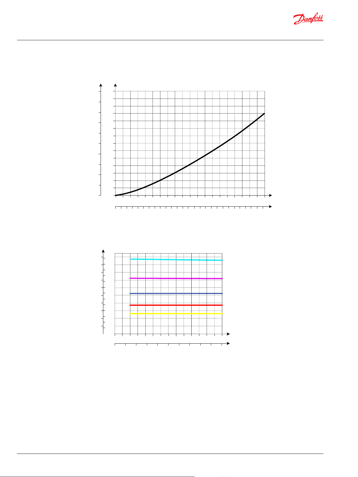
[psi] [bar]
P
Max
Min
Q
400
300
200
100
0
30
25
20
15
10
5
0
0 1 2 3 4 5
0 0.25 0.5 0.75 1.0 1.25
Q
[l/min]
[US gal/min]
P109211
Technical Information
PVG 128/256 Technical Information
PVPV Inlet Modules
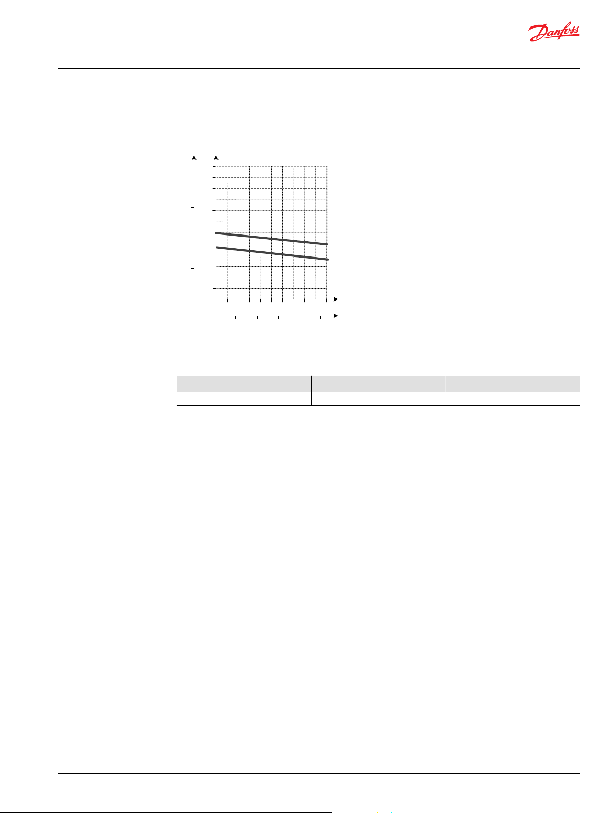
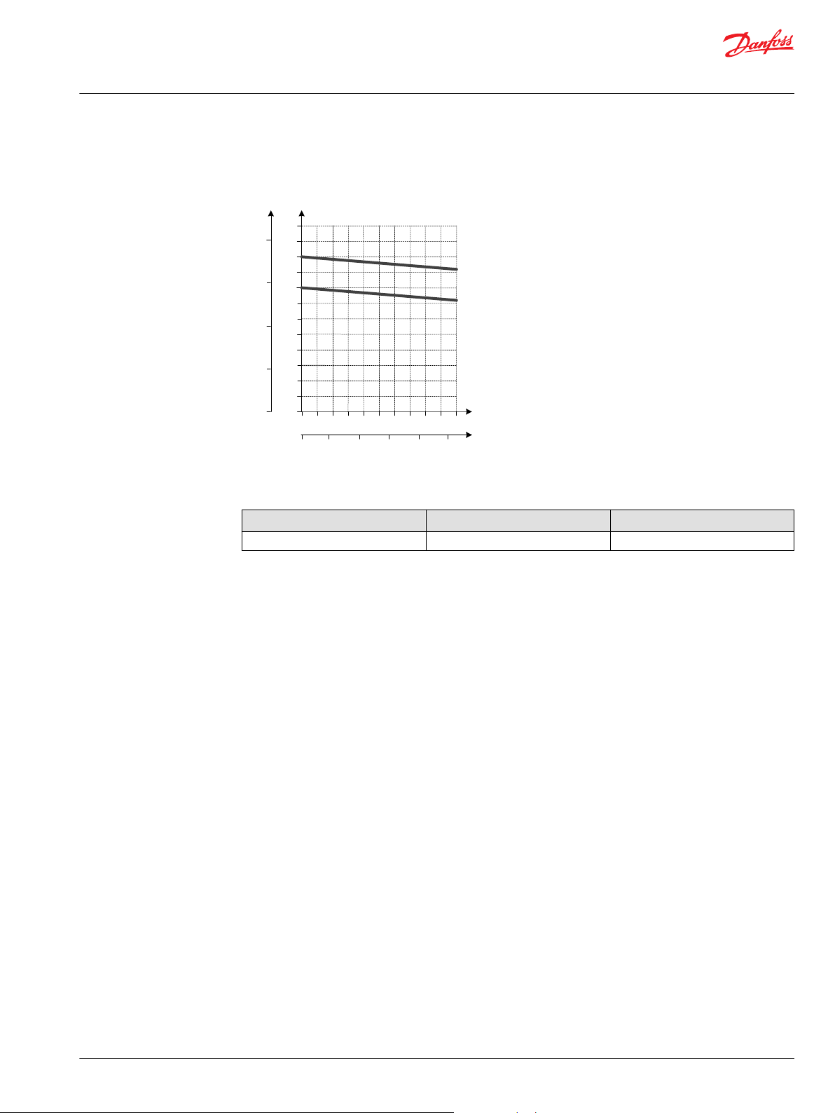
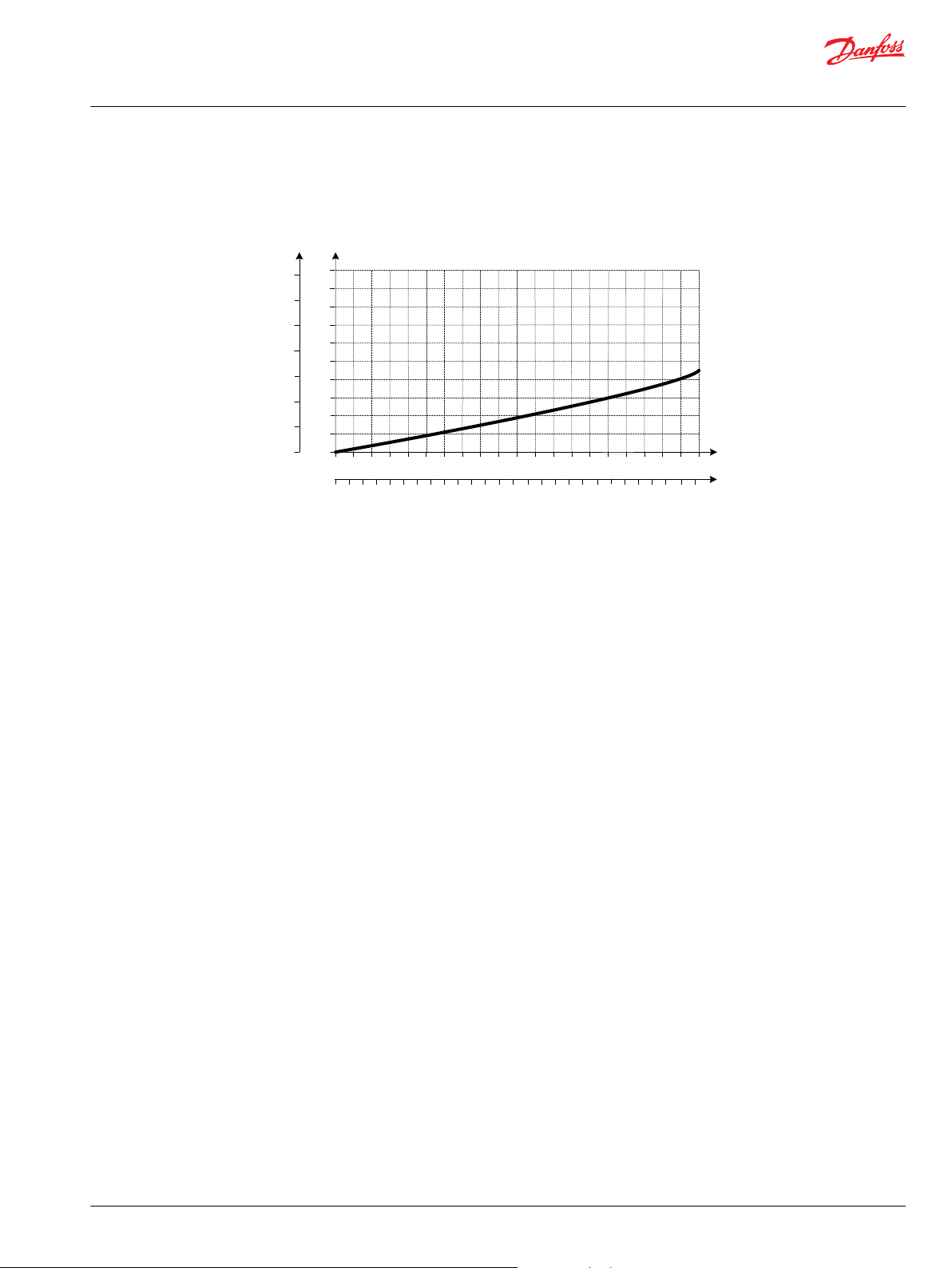
Pilot Pressure Reduction Valve Performance
Accessory module for PVPV 256
Ordering information 12 V 24 V
PVPP Pilot shut off valve 11160318 11160319
©
Danfoss | July 2021 BC220686485279en-000510 | 11
Page 12
P
Pp
T
T
LS
P
P109163
Technical Information
PVG 128/256 Technical Information
PVPV Inlet Modules
PPRV for PVH/PVHC Activation and/or Mechanical
The Closed Center PVPV inlet with integrated pilot pressure reduction valve (PPRV) for PVH/PVHC
activation is intended for use with variable displacement pumps in applications where a valve group with
PVH/PVHC controlled work sections is desired.
All Variants are prepared for 2xPVLP shock/anti-cavitation valves for pressure peak protection and anticavitation prevention.
Optional electrically actuated pilot shut off valve PVPP provides additional functional system safety by
removing pilot oil from the electrical actuation or hydraulic actuation system, disabling main spool
actuation.
Schematic
Technical data
Max. rated pressure P-port continuous 350 bar [5076 psi]
P-port intermittent 400 bar [5800 psi]
T-port static/dynamic 25/40 bar [363/580 psi]
Rated Port P (PVPV/PVSI) P-port 600/600 l/min [159/159 US gal/min]
Oil temperature Recommended 30 to 60°C [86 to 140°F]
Minimum -30°C [-22°F]
Maximum 90° [194°F]
Ambient temperature Recommended -30 to 60°C [-22 to 140°F]
Oil viscosity Operating range 12 to 75 mm2/s [65 to 347 SUS]
Minimum 4 mm2/s [39 SUS]
Maximum 460 mm2/s [2128 SUS]
Oil contamination
according to ISO 4406
Maximum 23/19/16
Part numbers for Closed Center PVPV with PPRV for PVH/PVHC
Part
number
11178095 PVH/PVHC
11178098 PVH/PVHC
11178117 PVH/PVHC
11178119 PVH/PVHC
PPRV P-port T-port
Metric
Flange
1-1/4”
Thread Ports
G1-1/2" BSP
SAE Flange
1-1/4” UNF
Thread Ports
1-7/8” UNF
Metric
Flange
1-1/2”
Thread Ports
G1-1/2" BSP
SAE Flange
1-1/2” UNF
Thread Ports
1-7/8” UNF
LS-port
Gauge-port
G3/8"BSP G3/8"BSP G1/4"BSP M12
G3/8"BSP G3/8"BSP G1/4"BSP M12
9/16-18 UNF 3/4-16 UNF 7/16-20 UNF M12
9/16-18 UNF 3/4-16 UNF 7/16-20 UNF M12
M-port
Gauge-port
T- and Pp
Gauge-port
Mounting
feet
12 | © Danfoss | July 2021 BC220686485279en-000510
Page 13
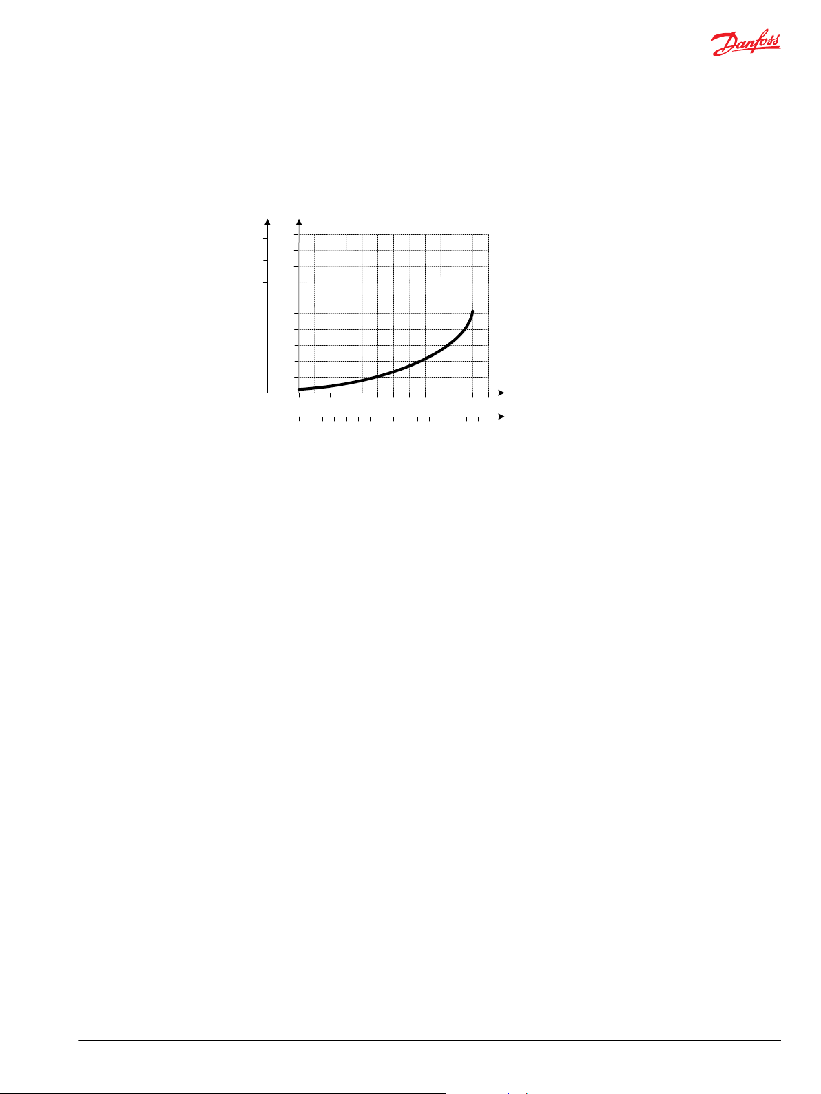
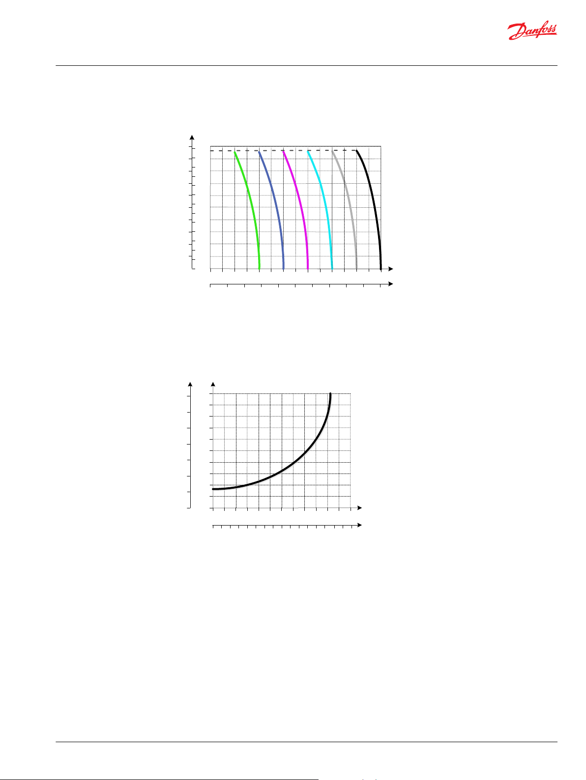
1 2 3 4 5
5
0
0
P
Max
Min
Q
Q
[psi] [bar]
400
300
200
100
0
30
25
20
15
10
0 0.25 0.5 0.75 1.0 1.25
[l/min]
[US gal/min]
P109212
Technical Information
PVG 128/256 Technical Information
PVPV Inlet Modules
Pilot Pressure Reduction Valve Performance
Accessory module for PVPV 256
Ordering information 12 V 24 V
PVPP Pilot shut off valve 11160318 11160319
©
Danfoss | July 2021 BC220686485279en-000510 | 13
Page 14
182.2
205
23.5
66
107
178.8
33
PVB 128
PVB 128 basic module dimensions (mm)
Weight 10 kg [22 lbs]
W
Technical Information
PVG 128/256 Technical Information
PVB 128 Variant Overview
The PVG 128 Basic modules (PVB), also referred to as work sections, is the interface between the PVG 128
proportional valve group and the work function such as a cylinder or a motor.
The PVB basic module variants are based on a generic platform with a selection of additional features,
enabling you to tailor the PVB to suit the demands of any hydraulic system.
The compensator is a 3-way type which include load drop check valve functionality, compensator
function and neutral relief which avoid A and B port pressure build up in neutral.
Symbol - compensated PVB
The generic PVB basic module platform includes the following main variants:
PVB 128 Compensated basic module.
Compensated PVB 128 w LSA/B Compensated basic module with LSA/B relief valve for each work port.
Compensated PVB 128 with LSA/B and PVLP Compensated basic module with LSA/B relief valve for each
work port and 2xPVLPs for each work port.
Warning
Risk of leak
The module will leak if the flange mount screws are not properly secured.
Flange mount screws according to ISO 6162-2.
14 | © Danfoss | July 2021 BC220686485279en-000510
Page 15
A
B
P109173
Technical Information
PVG 128/256 Technical Information
PVB 128 Variant Overview
PVB 128 3-way Compensator
The compensated PVB is intended for controlling a work function where the function behavior in terms
of flow and pressures requires independency on the load pressure of other functions used
simultaneously.
The compensator is a 3-way type which include load drop check valve functionality, compensator
function and neutral relief which avoid A and B port pressure build up in neutral.
Schematic
Technical data
Max. rated pressure A/B port continuous 350 bar [5076 psi]
Max. rated flow
Oil temperature Recommended 30 to 60°C [86 to 140°F]
Ambient temperature Recommended -30 to 60°C [-22 to 140°F]
Oil viscosity Operating range 12 to 75 mm2/s [65 to 347 SUS]
Oil contamination
according to ISO 4406
Max. internal leakage at 100
bar [1450 psi] and 21 mm2/s
[102 SUS]
*
Rated flow at 15 bar margin pressure
A/B port intermittent 400 [5800 psi]
*
A/B port 250 l/min [66 US gal/min]
Minimum -30°C [-22°F]
Maximum 90° [194°F]
Minimum 4 mm2/s [39 SUS]
Maximum 460 mm2/s [2128 SUS]
Maximum 23/19/16
A/B→T without shock valve 70 cm3/min [4.27 in3/min]
A/B→T with shock valve 80 cm3/min [4.88 in3/min
Part numbers for Compensated PVB 128
Part number A/B-port PVLP/PVLA LS A/B-port
11170522 Metric Flange 3/4” - 11170528 G 1" BSP - 11170524 SAE Flange 3/4” UNC - 11170526 Thread Ports 1 5/16 UNC - -
©
Danfoss | July 2021 BC220686485279en-000510 | 15
Page 16
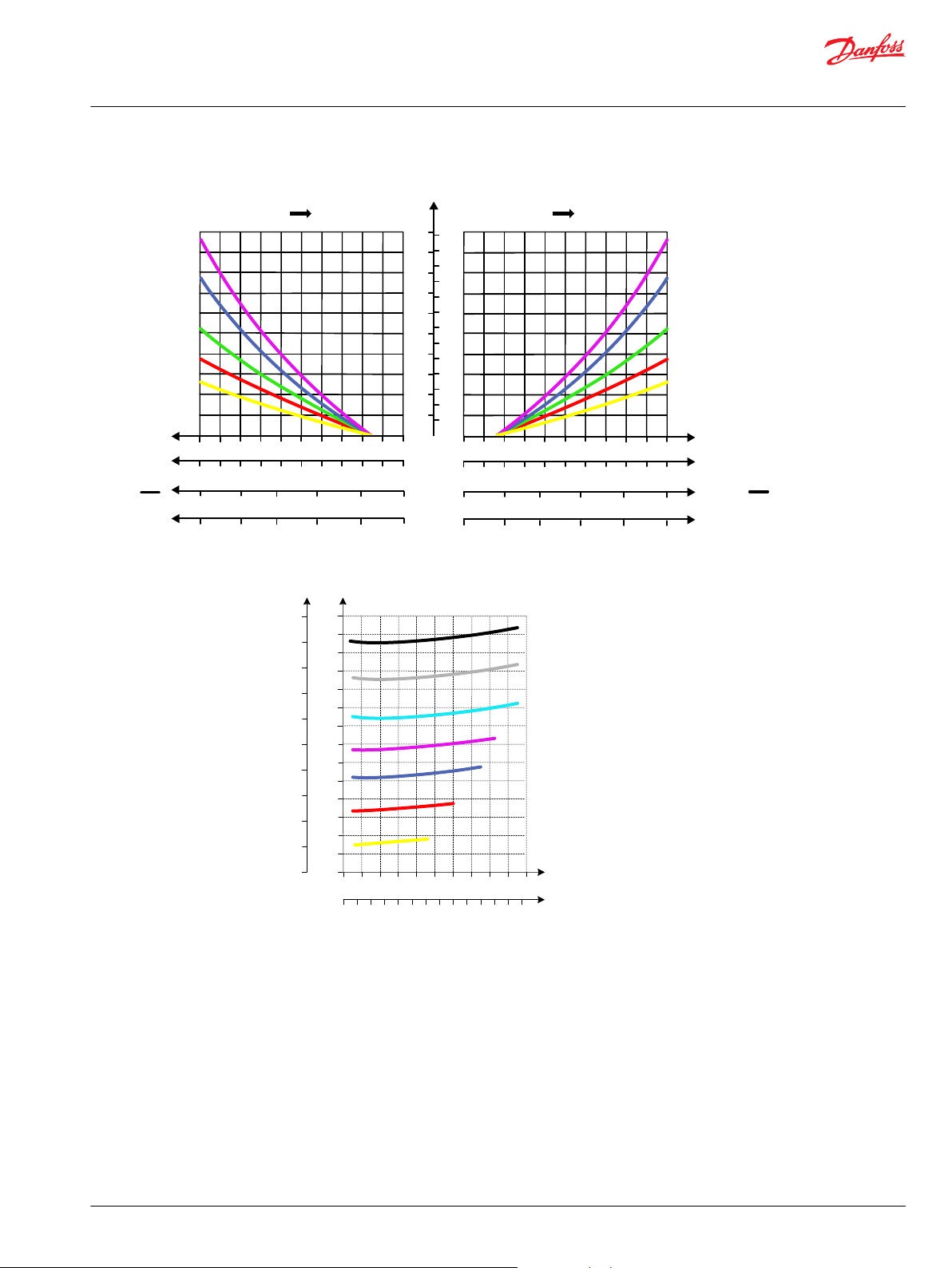
AP
25
50
75
100
125
150
175
200
225
250
[l/min] [US gal/min]
[mm]
PVM
01234567
[in]
PVM
00.040.080.120.160.200.240.28
PVEH
U
s
U
DC
8
0.31
910
0.350.39
5
10
15
20
25
30
35
40
45
50
55
60
65
A
B
C
D
E
BP
[mm]
PVM
1098765
[in]
PVM
0.390.350.310.280.240.20
U
s
U
DC
0.70.650.60.55
4
0.16
0.5
321
0
0.120.080.04
0.75
A
B
C
D
E
PVEH
PVEH-U
5.0
7.5
PVEH-U
0.450.40.350.3
0.25
0.5
2.5
5.0
[V]
[V]
0
25
50
75
100
125
150
175
200
225
250
[l/min] [US gal/min]
5
10
15
20
25
30
35
40
45
50
55
60
65
250225200175150125
100
755025
0
Q
350
325300275
P
P
25002000150010005000 35003000 4000 50004500
[b ar]
[p si]
P109213
Technical Information
PVG 128/256 Technical Information
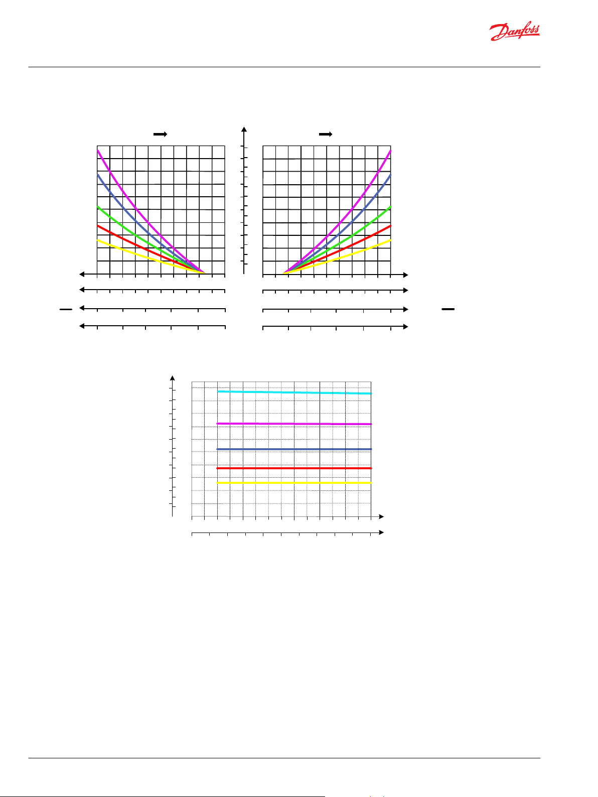
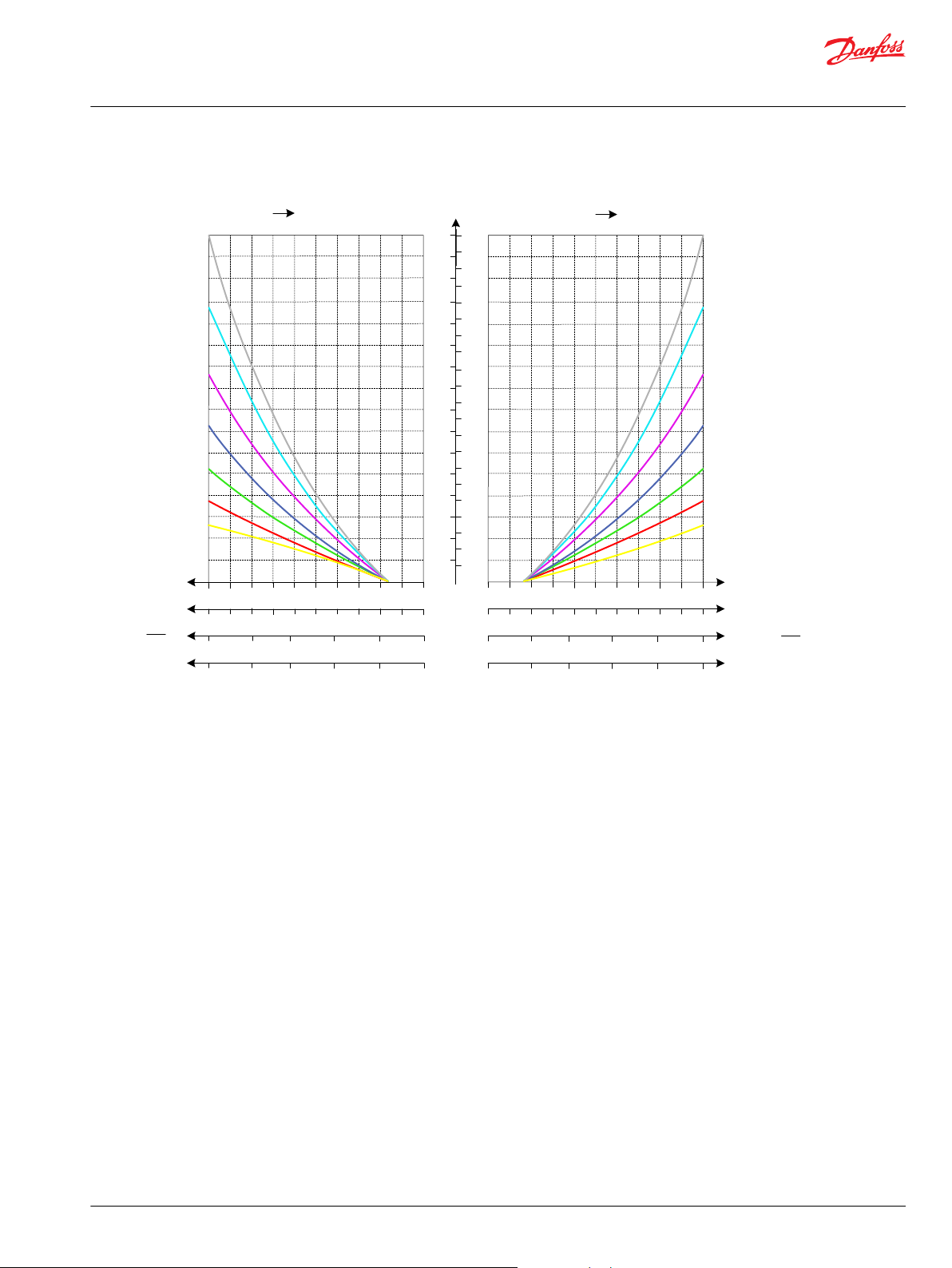
PVB 128 Variant Overview
Oil flow as function of spool travel
Load Independent Oil Flow, Pressure Compensated
16 | © Danfoss | July 2021 BC220686485279en-000510
Page 17
25 50 75 100 125 150 175 200 225 250 275 300
5 10 15 20 25 30 35 40 45 50 55 60 65 70 75 80
25
20
15
10
5
0
250
200
150
100
50
0
350
300
0
0
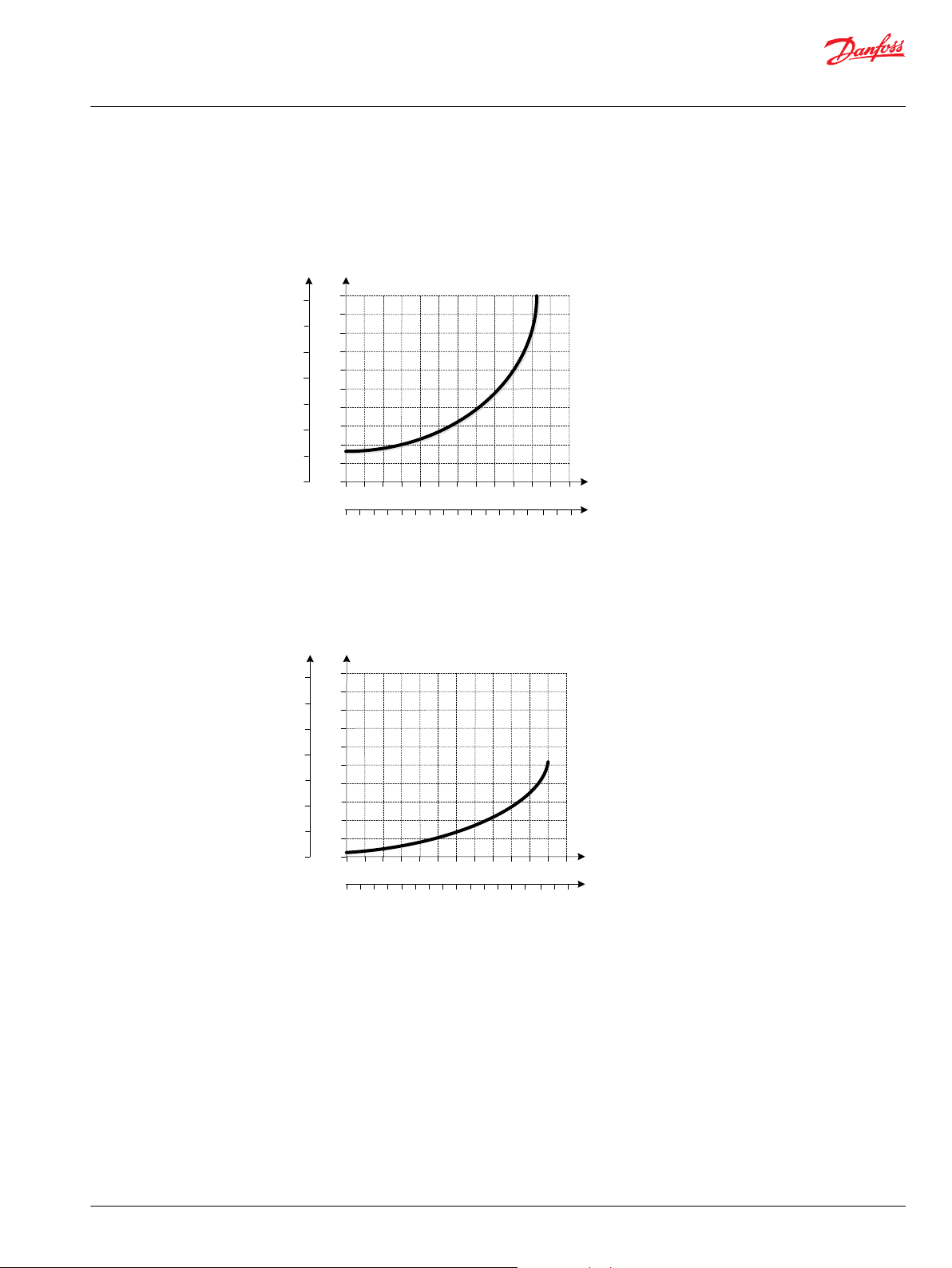
Port P to Port A/B at full spool stroke
E = Spool 240 l/min
P
Q
Q
[psi] [bar]
[l/min]
[US gal/min]
P109240
5
0
0
P
Port A/B to Tank at full spool stroke
Q
Q
[psi] [bar]
350
300
200
150
100
50
250
0 25 50 75 100 125 150 175 200 225 250 275 300
25
20
15
10
0 5 10 15 20 25 30 35 404550
55 60
65 70 75 80
E = Spool 240 l/min
[l/min]
[US gal/min]
P109241
Technical Information
PVG 128/256 Technical Information
PVB 128 Variant Overview
PVB 128 Upstream Performance
©
Danfoss | July 2021 BC220686485279en-000510 | 17
PVB 128 Downstream Performance
Page 18
A
B
LS/B
LS/A
P109186
Technical Information
PVG 128/256 Technical Information
PVB 128 Variant Overview
PVB 128 3-way Compensator with LS A/B
The compensated PVB is intended for controlling a work function where the function behavior in terms
of flow and pressures requires independency on the load pressure of other functions used
simultaneously.
The integrated LSA/B relief valves are used to limit the maximum work port pressure on the A and B-ports
individually.
The compensator is a 3-way type which include load drop check valve functionality, compensator
function and neutral relief which avoid A and B port pressure build up in neutral.
Schematic
Technical data
Max. rated pressure A/B port continuous 350 bar [5076 psi]
A/B port intermittent 400 [5800 psi]
Max. rated flow
Oil temperature Recommended 30 to 60°C [86 to 140°F]
Ambient temperature Recommended -30 to 60°C [-22 to 140°F]
Oil viscosity Operating range 12 to 75 mm2/s [65 to 347 SUS]
Oil contamination
according to ISO 4406
Max. internal leakage at 100
bar [1450 psi] and 21 mm2/s
[102 SUS]
*
Rated flow at 15 bar margin pressure
*
A/B port 250 l/min [66 US gal/min]
Minimum -30°C [-22°F]
Maximum 90° [194°F]
Minimum 4 mm2/s [39 SUS]
Maximum 460 mm2/s [2128 SUS]
Maximum 23/19/16
A/B→T without shock valve 70 cm3/min [4.27 in3/min]
A/B→T with shock valve 80 cm3/min [4.88 in3/min
Part numbers for Compensated PVB with LS A/B
Part number A/B-port PVLP/PVLA LS A/B-port
11176915 Metric Flange 3/4” - G1/4"BSP
11176918 G 1" BSP - G1/4"BSP
11176916 SAE Flange 3/4” UNC - 7/16-20 UNC
11176917 Thread Ports 1 5/16 UNC - 7/16-20 UNC
18 | © Danfoss | July 2021 BC220686485279en-000510
Page 19
AP
25
50
75
100
125
150
175
200
225
250
[l/min] [US gal/min]
[mm]
PVM
01234567
[in]
PVM
00.040.080.120.160.200.240.28
PVEH
U
s
U
DC
8
0.31
910
0.350.39
5
10
15
20
25
30
35
40
45
50
55
60
65
A
B
C
D
E
BP
[mm]
PVM
1098765
[in]
PVM
0.390.350.310.280.240.20
U
s
U
DC
0.70.650.60.55
4
0.16
0.5
321
0
0.120.080.04
0.75
A
B
C
D
E
PVEH
PVEH-U
5.0
7.5
PVEH-U
0.450.40.350.3
0.25
0.5
2.5
5.0
[V]
[V]
0
25
50
75
100
125
150
175
200
225
250
[l/min] [US gal/min]
5
10
15
20
25
30
35
40
45
50
55
60
65
250225200175150125
100
755025
0
Q
350
325300275
P
P
25002000150010005000 35003000 4000 50004500
[b ar]
[p si]
P109213
Technical Information
PVG 128/256 Technical Information
PVB 128 Variant Overview
Oil flow as function of spool travel
Load Independent Oil Flow, Pressure Compensated
©
Danfoss | July 2021 BC220686485279en-000510 | 19
Page 20
25
50
75
100
125
150
175
200
225
250
[l/min] [US gal/min]
5
10
15
20
25
30
35
40
45
50
55
60
65
250225200175150125
100
755025
0
Q
350
325300275
P
P
25002000150010005000 35003000 4000 50004500
0
[bar]
[psi]
P109215
25 50 75 100 125 150 175 200 225 250 275 300
5 10 15 20 25 30 35 40 45 50 55 60 65 70 75 80
25
20
15
10
5
0
250
200
150
100
50
0
350
300
0
0
Port P to Port A/B at full spool stroke
E = Spool 240 l/min
P
Q
Q
[psi] [bar]
[l/min]
[US gal/min]
P109240
Technical Information
PVG 128/256 Technical Information
PVB 128 Variant Overview
LS A/B Pressure Relief Valve
PVB 128 Upstream Performance
20 | © Danfoss | July 2021 BC220686485279en-000510
Page 21
5
0
0
P
Port A/B to Tank at full spool stroke
Q
Q
[psi] [bar]
350
300
200
150
100
50
250
0 25 50 75 100 125 150 175 200 225 250 275 300
25
20
15
10
0 5 10 15 20 25 30 35 404550
55 60
65 70 75 80
E = Spool 240 l/min
[l/min]
[US gal/min]
P109241
Technical Information
PVG 128/256 Technical Information
PVB 128 Variant Overview
PVB 128 Downstream Performance
©
Danfoss | July 2021 BC220686485279en-000510 | 21
Page 22
LS/B
LS/A
B
A
P109172
Technical Information
PVG 128/256 Technical Information
PVB 128 Variant Overview
PVB 128 3-way Compensator with LS A/B and PVLP
The compensated PVB is intended for controlling a work function where the function behavior in terms
of flow and pressures requires independency on the load pressure of other functions used
simultaneously.
The integrated LS A/B relief valves are used to limit the maximum work port pressure on the A and Bports individually.
Featuring 2xPVLP shock/anti-cavitation valves on each work port for pressure peak protection and anticavitation prevention
The compensator is a 3-way type which include load drop check valve functionality, compensator
function and neutral relief which avoid A and B port pressure build up in neutral.
Schematic
Technical data
Max. rated pressure A/B port continuous 350 bar [5076 psi]
A/B port intermittent 400 [5800 psi]
Max. rated flow
Oil temperature Recommended 30 to 60°C [86 to 140°F]
Ambient temperature Recommended -30 to 60°C [-22 to 140°F]
Oil viscosity Operating range 12 to 75 mm2/s [65 to 347 SUS]
Oil contamination
according to ISO 4406
Max. internal leakage at 100
bar [1450 psi] and 21 mm2/s
[102 SUS]
*
Rated flow at 15 bar margin pressure
*
A/B port 250 l/min [66 US gal/min]
Minimum -30°C [-22°F]
Maximum 90° [194°F]
Minimum 4 mm2/s [39 SUS]
Maximum 460 mm2/s [2128 SUS]
Maximum 23/19/16
A/B→T without shock valve 70 cm3/min [4.27 in3/min]
A/B→T with shock valve 80 cm3/min [4.88 in3/min
Part numbers for Compensated PVB 128 with LSA/B and PVLP
Part number A/B-port PVLP/PVLA LS A/B-port
11165621 Metric Flange 3/4” 2 PVLP/PVLA G1/4"BSP
11170527 G 1" BSP 2 PVLP/PVLA G1/4"BSP
11170523 SAE Flange 3/4” UNC 2 PVLP/PVLA 7/16-20 UNC
11170525 Thread Ports 1 5/16 UNC 2 PVLP/PVLA 7/16-20 UNC
22 | © Danfoss | July 2021 BC220686485279en-000510
Page 23
AP
25
50
75
100
125
150
175
200
225
250
[l/min] [US gal/min]
[mm]
PVM
01234567
[in]
PVM
00.040.080.120.160.200.240.28
PVEH
U
s
U
DC
8
0.31
910
0.350.39
5
10
15
20
25
30
35
40
45
50
55
60
65
A
B
C
D
E
BP
[mm]
PVM
1098765
[in]
PVM
0.390.350.310.280.240.20
U
s
U
DC
0.70.650.60.55
4
0.16
0.5
321
0
0.120.080.04
0.75
A
B
C
D
E
PVEH
PVEH-U
5.0
7.5
PVEH-U
0.450.40.350.3
0.25
0.5
2.5
5.0
[V]
[V]
0
25 50 75 100 125 150 175 200 225 250
[l/min]
[USgal/min]
5 10 15 20 25 30 35 40 45 50 55 60 65
250
225
200
175
150
125
100
75
50
25
0
Q
350
325
300
275
PP
2500
2000
1500
1000
500
0
3500
3000
4000
5000
4500
0
[psi] [bar]
0
Q
P109216
Technical Information
PVG 128/256 Technical Information
PVB 128 Variant Overview
Oil flow as function of spool travel
©
Danfoss | July 2021 BC220686485279en-000510 | 23
2xPVLP Shock Valve
Page 24
25 50 75 100 125 150 175 200 225 250 275 300 325
[l/min]
[US gal/min]
350 375 400
5 10 15 20 25 30 35 40 45 50 55 60 65 70 75 80 85 90 95 100105
50
45
40
35
30
25
20
15
10
5
0
425 450 475 500
110115120 125130
Q
70
65
60
55
PP
500
400
300
200
100
0
700
600
800
1000
900
0
[ps i] [ bar ]
0
Q
Po rt A /B
P109217
25
50
75
100
125
150
175
200
225
250
[l/min] [US gal/min]
5
10
15
20
25
30
35
40
45
50
55
60
65
250225200175150125
100
755025
0
Q
350
325300275
P
P
25002000150010005000 35003000 4000 50004500
[b ar]
[p si]
P109213
Technical Information
PVG 128/256 Technical Information
PVB 128 Variant Overview
2xPVLA Suction Valve
Load Independent Oil Flow, Pressure Compensated
24 | © Danfoss | July 2021 BC220686485279en-000510
Page 25
25
50
75
100
125
150
175
200
225
250
[l/min] [US gal/min]
5
10
15
20
25
30
35
40
45
50
55
60
65
250225200175150125
100
755025
0
Q
350
325300275
P
P
25002000150010005000 35003000 4000 50004500
0
[bar]
[psi]
P109215
25 50 75 100 125 150 175 200 225 250 275 300
5 10 15 20 25 30 35 40 45 50 55 60 65 70 75 80
25
20
15
10
5
0
250
200
150
100
50
0
350
300
0
0
Port P to Port A/B at full spool stroke
E = Spool 240 l/min
P
Q
Q
[psi] [bar]
[l/min]
[US gal/min]
P109240
Technical Information
PVG 128/256 Technical Information
PVB 128 Variant Overview
LS A/B Pressure Relief Valve
PVB 128 Upstream Performance
©
Danfoss | July 2021 BC220686485279en-000510 | 25
Page 26
5
0
0
P
Port A/B to Tank at full spool stroke
Q
Q
[psi] [bar]
350
300
200
150
100
50
250
0 25 50 75 100 125 150 175 200 225 250 275 300
25
20
15
10
0 5 10 15 20 25 30 35 404550
55 60
65 70 75 80
E = Spool 240 l/min
[l/min]
[US gal/min]
P109241
Technical Information
PVG 128/256 Technical Information
PVB 128 Variant Overview
PVB 128 Downstream Performance
26 | © Danfoss | July 2021 BC220686485279en-000510
Page 27
182.2
205
23.5
86
107
178.5
43
PVB 256
PVB 256 basic module dimensions (mm)
Weight 16 kg [35.3 lbs]
Technical Information
PVG 128/256 Technical Information
PVB 256 Variant Overview
The PVG 256 Basic modules (PVB), also referred to as work sections, is the interface between the PVG 256
proportional valve group and the work function such as a cylinder or a motor.
The PVB basic module variants are based on a generic platform with a selection of additional features,
enabling you to tailor the PVB to suit the demands of any hydraulic system.
The compensator is a 3-way type which includes load drop check valve functionality, compensator
function and neutral relief which avoid A and B port pressure build up.
The generic PVB basic module platform includes the following main variants.
Compensated PVB 256 Compensated basic module.
Compensated PVB 256 with LS A/B Compensated basic module with LSA/B relief valve for each work port.
Compensated PVB 256 with LS A/B and PVLP Compensated basic module with LSA/B relief valve for each
work port and 3xPVLPs for each work port.
Compensated PVB 256 with Turbo compensator feature Compensated basic module with LS A/B relief valve
for each work port and 3xPVLPs for each work port.
©
Danfoss | July 2021 BC220686485279en-000510 | 27
Page 28
A
B
P109168
Technical Information
PVG 128/256 Technical Information
PVB 256 Variant Overview
PVB 256 3-way Compensator
The compensated PVB is intended for controlling a work function where the function behavior in terms
of flow and pressures requires independency on the load pressure of other functions used
simultaneously.
The integrated LS A/B relief valves are used to limit the maximum work port pressure on the A and Bports individually.
The compensator is a 3-way type which include load drop check valve functionality, compensator
function and neutral relief which avoid A and B port pressure build up in neutral.
Schematic
Technical data
Max. rated pressure A/B port continuous 350 bar [5076 psi]
A/B port intermittent 400 bar [5800 psi]
Max. rated flow A/B port 450 l/min [119 US gal/min]
Oil temperature Recommended 30 to 60°C [86 to 140°F]
Minimum -30°C [-22°F]
Maximum 90° [194°F]
Ambient temperature Recommended -30 to 60°C [-22 to 140°F]
Oil viscosity Operating range 12 to 75 mm2/s [65 to 347 SUS]
Minimum 4 mm2/s [39 SUS]
Maximum 460 mm2/s [2128 SUS]
Oil contamination
according to ISO 4406
Max. internal leakage at 100
bar [1450 psi] and 21 mm2/s
[102 SUS]
Maximum 23/19/16
A/B→T without shock valve 70 cm3/min [4.27 in3/min]
A/B→T with shock valve 85 cm3/min [5.19 in3/min]
Part numbers for Compensated PVB 256
Part number A/B port PVLP/PVLA LS A/B port
11169244 Metric Flange 1” - 11169252 G1 BSP - 11169248 SAE Flange 1” UNC - 11177020 Thread Ports 1-5/16-12 UNC - -
28 | © Danfoss | July 2021 BC220686485279en-000510
Page 29

A
P
25
50
75
100
125
150
175
200
225
250
275
300
325
[l/min] [US gal/min]
[mm]
PVM
01234567
[in]
PVM
0
0.04
0.080.120.160 .20
0.24
0.28
PVEH
U
s
U
DC
0.50.45
0.40.350.3
8
0.31
0.25
9
10
350
375
400
0.35
0.39
5
10
15
20
25
30
35
40
45
50
55
60
65
70
75
80
85
90
95
100
105
BP
[mm]
PVM
1098765
[in]
PVM
0.390.350.310. 280.240.20
PVEH
U
s
U
DC
0.70.650.60.55
4
0.16
0.5
3210
0.120.080.040
0.75
PVEH-U
5.0
2.5
PVEH-U
5.0
7.5
[V]
[V]
A
B
C
D
E
F
G
A
B
C
D
E
F
G
Technical Information
PVG 128/256 Technical Information
PVB 256 Variant Overview
Oil Flow as Function of Spool Travel
©
Danfoss | July 2021 BC220686485279en-000510 | 29
Page 30

25
50
75
100
125
150
175
200
225
250
275
300
325
[l/min] [US gal/min]
350
375
400
5
10
15
20
25
30
35
40
45
50
55
60
65
70
75
80
85
90
95
100
105
250225200175150125
100
755025
0
425
450
475
500
110
115
120
125
130
Q
350
325300275
P
P
25002000150010005000 35003000 4000 50004500
[bar]
[psi]
P109219
25 50 75 100 125 150 175 200 225 250 275 300 325 350 375 400
5 10 15 20 25 30 35 40 45 50 55 60 65 70 75 80 85 90 95 100105
25
20
15
10
5
0
425
110
250
200
150
100
50
0
350
300
0
0
P
[psi] [bar]
Q
Q
[l/min]
[US gal/min]
Port P to Port A/B at full spool stroke
G = Spool 400 l/min
P109243
Technical Information
PVG 128/256 Technical Information
PVB 256 Variant Overview
Load Independent Oil Flow, Pressure Compensated
PVB 256 Upstream Performance
30 | © Danfoss | July 2021 BC220686485279en-000510
Page 31
25 50 75 100 125 150 175 200 225 250 275 300 325 350 375 400
5 10 15 20 25 30 35 40 45 50 55 60 65 70 75 80 85 90 95 100105
25
20
15
10
5
0
425 450 475 500
110115120 125130
Q
P
250
200
150
100
50
0
350
300
0
0
Q
G/H = Spool 400 l/min
[psi] [bar]
[l/min]
[US gal/min]
Port A/B to Tank at full spool stroke
P109244
Technical Information
PVG 128/256 Technical Information
PVB 256 Variant Overview
PVB 256 Downstream Performance
©
Danfoss | July 2021 BC220686485279en-000510 | 31
Page 32

LS/B
LS/A
A
B
P109167
Technical Information
PVG 128/256 Technical Information
PVB 256 Variant Overview
PVB 256 3-way Compensator with LS A/B
The compensated PVB is intended for controlling a work function where the function behavior in terms
of flow and pressures requires independency on the load pressure of other functions used
simultaneously.
The integrated LS A/B relief valves are used to limit the maximum work port pressure on the A and Bports individually.
The compensator is a 3-way type which include load drop check valve functionality, compensator
function and neutral relief which avoid A and B port pressure build up in neutral.
Schematic
Technical data
Max. rated pressure A/B port continuous 350 bar [5076 psi]
A/B port intermittent 400 [5800 psi]
Max. rated flow A/B port 450 l/min [119 US gal/min]
Oil temperature Recommended 30 to 60°C [86 to 140°F]
Minimum -30°C [-22°F]
Maximum 90° [194°F]
Ambient temperature Recommended -30 to 60°C [-22 to 140°F]
Oil viscosity Operating range 12 to 75 mm2/s [65 to 347 SUS]
Minimum 4 mm2/s [39 SUS]
Maximum 460 mm2/s [2128 SUS]
Oil contamination
according to ISO 4406
Max. internal leakage at 100
bar [1450 psi] and 21 mm2/s
[102 SUS]
Maximum 23/19/16
A/B→T without shock valve 70 cm3/min [4.27 in3/min]
A/B→T with shock valve 85 cm3/min [5.19 in3/min]
Part numbers for Compensated PVB 256 with LSA/B
Part number A/B-port PVLP/PVLA LS A/B-port
11177015 Metric Flange 1” - G1/4"BSP
11177017 G1-1/4 BSP - G1/4"BSP
11177016 SAE Flange 1” UNC - 7/16-20 UNC
11177019 Thread Ports 1-5/16-12 UNC - 7/16-20 UNC
32 | © Danfoss | July 2021 BC220686485279en-000510
Page 33
A
P
25
50
75
100
125
150
175
200
225
250
275
300
325
[l/min] [US gal/min]
[mm]
PVM
01234567
[in]
PVM
0
0.04
0.080.120.160 .20
0.24
0.28
PVEH
U
s
U
DC
0.50.45
0.40.350.3
8
0.31
0.25
9
10
350
375
400
0.35
0.39
5
10
15
20
25
30
35
40
45
50
55
60
65
70
75
80
85
90
95
100
105
BP
[mm]
PVM
1098765
[in]
PVM
0.390.350.310. 280.240.20
PVEH
U
s
U
DC
0.70.650.60.55
4
0.16
0.5
3210
0.120.080.040
0.75
PVEH-U
5.0
2.5
PVEH-U
5.0
7.5
[V]
[V]
A
B
C
D
E
F
G
A
B
C
D
E
F
G
Technical Information
PVG 128/256 Technical Information
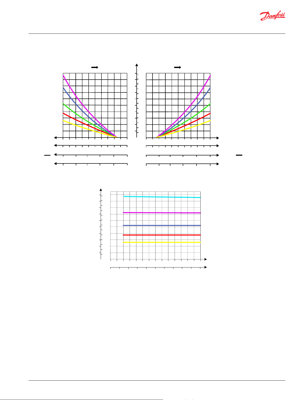
PVB 256 Variant Overview
Oil Flow as Function of Spool Travel
©
Danfoss | July 2021 BC220686485279en-000510 | 33
Page 34

25
50
75
100
125
150
175
200
225
250
275
300
325
[l/min] [US gal/min]
350
375
400
5
10
15
20
25
30
35
40
45
50
55
60
65
70
75
80
85
90
95
100
105
250225200175150125
100
755025
0
425
450
475
500
110
115
120
125
130
Q
350
325300275
P
P
25002000150010005000 35003000 4000 50004500
[bar]
[psi]
P109219
25
50
75
100
125
150
175
200
225
250
275
300
325
[l/min] [US gal/min]
350
375
400
5
10
15
20
25
30
35
40
45
50
55
60
65
70
75
80
85
90
95
100
105
250225200175150125100
7550250
Q
350
325300275
P
P
25002000150010005000 35003000 4000 50004500
LS A/B Pressure Limitation
0
[bar]
[psi]
425
450
475
500
525
110
115
120
125
130
135
550
140
Technical Information
PVG 128/256 Technical Information
PVB 256 Variant Overview
Load Independent Oil Flow, Pressure Compensated
LS A/B Pressure Limitation
34 | © Danfoss | July 2021 BC220686485279en-000510
Page 35

25 50 75 100 125 150 175 200 225 250 275 300 325 350 375 400
5 10 15 20 25 30 35 40 45 50 55 60 65 70 75 80 85 90 95 100105
25
20
15
10
5
0
425
110
250
200
150
100
50
0
350
300
0
0
P
[psi] [bar]
Q
Q
[l/min]
[US gal/min]
Port P to Port A/B at full spool stroke
G = Spool 400 l/min
P109243
25 50 75 100 125 150 175 200 225 250 275 300 325 350 375 400
5 10 15 20 25 30 35 40 45 50 55 60 65 70 75 80 85 90 95 100105
25
20
15
10
5
0
425 450 475 500
110115120 125130
Q
P
250
200
150
100
50
0
350
300
0
0
Q
G/H = Spool 400 l/min
[psi] [bar]
[l/min]
[US gal/min]
Port A/B to Tank at full spool stroke
P109244
Technical Information
PVG 128/256 Technical Information
PVB 256 Variant Overview
PVB 256 Upstream Performance
PVB 256 Downstream Performance
©
Danfoss | July 2021 BC220686485279en-000510 | 35
Page 36

LS/B
LS/A
A
B
P109166
Technical Information
PVG 128/256 Technical Information
PVB 256 Variant Overview
PVB 256 3-way Compensator with LSA/B and PVLP
The compensated PVB is intended for controlling a work function where the function behavior in terms
of flow and pressures requires independency on the load pressure of other functions used
simultaneously.
The integrated LS A/B relief valves are used to limit the maximum work port pressure on the A and Bports individually.
Featuring 3xPVLP shock/anti-cavitation valves on each work port for pressure peak protection and anticavitation prevention.
The compensator is a 3-way type which include load drop check valve functionality, compensator
function and neutral relief which avoid A and B port pressure build up in neutral.
Technical data
Max. rated pressure A/B port continuous 350 bar [5076 psi]
A/B port intermittent 400 bar [5800 psi]
Max. rated flow A/B port 450 l/min [119 US gal/min]
Oil temperature Recommended 30 to 60°C [86 to 140°F]
Minimum -30°C [-22°F]
Maximum 90° [194°F]
Ambient temperature Recommended -30 to 60°C [-22 to 140°F]
Oil viscosity Operating range 12 to 75 mm2/s [65 to 347 SUS]
Minimum 4 mm2/s [39 SUS]
Maximum 460 mm2/s [2128 SUS]
Oil contamination
according to ISO 4406
Max. internal leakage at 100
bar [1450 psi] and 21 mm2/s
[102 SUS]
Maximum 23/19/16
A/B→T without shock valve 70 cm3/min [4.27 in3/min]
A/B→T with shock valve 85 cm3/min [5.19 in3/min]
Part numbers for Compensated PVB 256 with LSA/B and PVLP
Part number A/B port PVLP/PVLA LS A/B port
11169243 Metric Flange 1” 3 PVLP/PVLA G1/4"BSP
11169251 G1 BSP 3 PVLP/PVLA G1/4"BSP
11169247 SAE Flange 1” UNC 3 PVLP/PVLA 7/16-20 UNC
11177018 Thread Ports 1-5/16-12 UNC 3 PVLP/PVLA 7/16-20 UNC
36 | © Danfoss | July 2021 BC220686485279en-000510
Page 37

A
P
25
50
75
100
125
150
175
200
225
250
275
300
325
[l/min] [US gal/min]
[mm]
PVM
01234567
[in]
PVM
0
0.04
0.080.120.160 .20
0.24
0.28
PVEH
U
s
U
DC
0.50.45
0.40.350.3
8
0.31
0.25
9
10
350
375
400
0.35
0.39
5
10
15
20
25
30
35
40
45
50
55
60
65
70
75
80
85
90
95
100
105
BP
[mm]
PVM
1098765
[in]
PVM
0.390.350.310. 280.240.20
PVEH
U
s
U
DC
0.70.650.60.55
4
0.16
0.5
3210
0.120.080.040
0.75
PVEH-U
5.0
2.5
PVEH-U
5.0
7.5
[V]
[V]
A
B
C
D
E
F
G
A
B
C
D
E
F
G
25 50 75 100 125 150 175 200 225 250 275 300 325
[l/min]
[US gal/min]
350 375
5 10 15 20 25 30 35 40 45 50 55 60 65 70 75 80 85 90 95 100
250
225
200
175
150
125
100
75
50
25
0
Q
350
325
300
275
PP
2500
2000
1500
1000
500
0
3500
3000
4000
5000
4500
0
[psi] [bar]
0
Q
P109221
Technical Information
PVG 128/256 Technical Information
PVB 256 Variant Overview
Oil Flow as Function of Spool Travel
3xPVLP Shock Valve
©
Danfoss | July 2021 BC220686485279en-000510 | 37
Page 38

25 50 75 100 125 150 175 200 225 250 275 300 325
[l/min]
[US gal/ min]
350 375 400
5 10 15 20 25 30 35 40 45 50 55 60 65 70 75 80 85 90 95 100105
50
45
40
35
30
25
20
15
10
5
0
425 450 475 500
110115120 125 130
Q
70
65
60
55
PP
500
400
300
200
100
0
700
600
800
1000
900
0
[psi] [bar]
0
Q
Port A/B
P109224
25
50
75
100
125
150
175
200
225
250
275
300
325
[l/min] [US gal/min]
350
375
400
5
10
15
20
25
30
35
40
45
50
55
60
65
70
75
80
85
90
95
100
105
25022 52001 751501251 00
7550250
Q
350
325300275
P
P
25002000150010005000 35003000 4000 50004500
LS A/B Pressure Limitation
0
[bar]
[psi]
425
450
475
500
525
110
115
120
125
130
135
550
140
Technical Information
PVG 128/256 Technical Information
PVB 256 Variant Overview
3xPVLA Suction Valve
LS A/B Pressure Limitation
38 | © Danfoss | July 2021 BC220686485279en-000510
Page 39

25
50
75
100
125
150
175
200
225
250
275
300
325
[l/min] [US gal/min]
350
375
400
5
10
15
20
25
30
35
40
45
50
55
60
65
70
75
80
85
90
95
100
105
250225200175150125
100
755025
0
425
450
475
500
110
115
120
125
130
Q
350
325300275
P
P
25002000150010005000 35003000 4000 50004500
[bar]
[psi]
P109219
25 50 75 100 125 150 175 200 225 250 275 300 325 350 375 400
5 10 15 20 25 30 35 40 45 50 55 60 65 70 75 80 85 90 95 100105
25
20
15
10
5
0
425
110
250
200
150
100
50
0
350
300
0
0
P
[psi] [bar]
Q
Q
[l/min]
[US gal/min]
Port P to Port A/B at full spool stroke
G = Spool 400 l/min
P109243
Technical Information
PVG 128/256 Technical Information
PVB 256 Variant Overview
Load Independent Oil Flow, Pressure Compensated
PVB 256 Upstream Performance
©
Danfoss | July 2021 BC220686485279en-000510 | 39
Page 40

25 50 75 100 125 150 175 200 225 250 275 300 325 350 375 400
5 10 15 20 25 30 35 40 45 50 55 60 65 70 75 80 85 90 95 100105
25
20
15
10
5
0
425 450 475 500
110115120 125130
Q
P
250
200
150
100
50
0
350
300
0
0
Q
G/H = Spool 400 l/min
[psi] [bar]
[l/min]
[US gal/min]
Port A/B to Tank at full spool stroke
P109244
Technical Information
PVG 128/256 Technical Information
PVB 256 Variant Overview
PVB 256 Downstream Performance
40 | © Danfoss | July 2021 BC220686485279en-000510
Page 41

LS/B
LS/A
A
B
P109169
Technical Information
PVG 128/256 Technical Information
PVB 256 Variant Overview
PVB 256 3-way Compensator with LS A/B, PVLP and Turbo
The compensated PVB is intended for controlling a work function where the function behavior in terms
of flow and pressures requires independency on the load pressure of other functions used
simultaneously.
The integrated LS A/B relief valves are used to limit the maximum work port pressure on the A and Bports individually.
Featuring 3xPVLP shock/anti-cavitation valves on each work port for pressure peak protection and anticavitation prevention.
The compensator is a 3-way type which include load drop check valve functionality, compensator
function and neutral relief which avoid A and B port pressure build up in neutral.
Schematic
Technical data
Max. rated pressure A/B port continuous 350 bar [5076 psi]
A/B port intermittent 400 bar [5800 psi]
Max. rated flow A/B port 500 l/min [132 US gal/min]
Oil temperature Recommended 30 to 60°C [86 to 140°F]
Minimum -30°C [-22°F]
Maximum 90° [194°F]
Ambient temperature Recommended -30 to 60°C [-22 to 140°F]
Oil viscosity Operating range 12 to 75 mm2/s [65 to 347 SUS]
Minimum 4 mm2/s [39 SUS]
Maximum 460 mm2/s [2128 SUS]
Oil contamination
according to ISO 4406
Max. internal leakage at 100
bar [1450 psi] and 21 mm2/s
[102 SUS]
Maximum 23/19/16
A/B→T without shock valve 70 cm3/min [4.27 in3/min]
A/B→T with shock valve 85 cm3/min [5.19 in3/min]
Part numbers for Compensated PVB 256 with LSA/B, PVLP and Turbo
Part number A/B port PVLP/PVLA LS A/B port
11183379 Metric Flange 1” 3 PVLP/PVLA G1/4"BSP
11183406 G1 BSP 3 PVLP/PVLA G1/4"BSP
11183404 SAE Flange 1” UNC 3 PVLP/PVLA 7/16-20 UNC
11183402 Thread Ports 1-5/16-1 UNC 3 PVLP/PVLA 7/16-20 UNC
©
Danfoss | July 2021 BC220686485279en-000510 | 41
Page 42

A
P
25
50
75
100
125
150
175
200
225
250
275
300
325
[l/min]
[US gal/min]
[mm]
PVM
0
1
2
3
4
5
6
7
[in]
PVM
0
0.040.080.120.1 60.20
0.24
0.28
PVEH
U
s
U
DC
0.5
0.45
0.40.35
0.3
8
0.31
0.25
9
10
350
375
400
0.350.39
5
10
15
20
25
30
35
40
45
50
55
60
65
70
75
80
85
90
95
100
105
B
P
[mm]
PVM
10
987
65
[in]
PVM
0.390.35
0.310.280.240.20
PVEH
U
s
U
DC
0.7
0.65
0.6
0.55
4
0.16
0.5
32
10
0.120.08
0.04
0
0.75
425
450
475
500
110
115
120
125
130
PVEH-U
5.0
2.5
PVEH-U
5.0
7.5
[V]
[V]
A
B
C
D
E
F
G
H
A
B
C
D
E
F
G
H
Technical Information
PVG 128/256 Technical Information
PVB 256 Variant Overview
Oil Flow as Function of Spool Travel
42 | © Danfoss | July 2021 BC220686485279en-000510
Page 43

25 50 75 100 125 150 175 200 225 250 275 300 325
[l/min]
[US gal/min]
350 375
5 10 15 20 25 30 35 40 45 50 55 60 65 70 75 80 85 90 95 100
250
225
200
175
150
125
100
75
50
25
0
Q
350
325
300
275
PP
2500
2000
1500
1000
500
0
3500
3000
4000
5000
4500
0
[psi] [bar]
0
Q
P109221
25 50 75 100 125 150 175 200 225 250 275 300 325
[l/min]
[US gal/ min]
350 375 400
5 10 15 20 25 30 35 40 45 50 55 60 65 70 75 80 85 90 95 100105
50
45
40
35
30
25
20
15
10
5
0
425 450 475 500
110115120 125 130
Q
70
65
60
55
PP
500
400
300
200
100
0
700
600
800
1000
900
0
[psi] [bar]
0
Q
Port A/B
P109224
Technical Information
PVG 128/256 Technical Information
PVB 256 Variant Overview
3xPVLP Shock Valve
3xPVLA Suction Valve
©
Danfoss | July 2021 BC220686485279en-000510 | 43
Page 44

25
50
75
100
125
150
175
200
225
250
275
300
325
[l/min] [US gal/min]
350
375
400
5
10
15
20
25
30
35
40
45
50
55
60
65
70
75
80
85
90
95
100
105
25022 52001 751501251 00
7550250
Q
350
325300275
P
P
25002000150010005000 35003000 4000 50004500
LS A/B Pressure Limitation
0
[bar]
[psi]
425
450
475
500
525
110
115
120
125
130
135
550
140
25
50
75
100
125
150
175
200
225
250
275
300
325
[l/min] [US gal/min]
350
375
400
5
10
15
20
25
30
35
40
45
50
55
60
65
70
75
80
85
90
95
100
105
250225200175150125
100
755025
0
425
450
475
500
110
115
120
125
130
Q
350
325300275
P
P
25002000150010005000 35003000 4000 50004500
[bar]
[psi]
P109219
Technical Information
PVG 128/256 Technical Information
PVB 256 Variant Overview
LS A/B Pressure Limitation
Load Independent Oil Flow, Pressure Compensated
44 | © Danfoss | July 2021 BC220686485279en-000510
Page 45

25 50 75 100 125 150 175 200 225 250 275 300 325 350 375 400
5 10 15 20 25 30 35 40 45 50 55 60 65 70 75 80 85 90 95 100105
25
20
15
10
5
0
425 450 475 500
110115120 125130
Q
P
250
200
150
100
50
0
350
300
0
0
Q
H = Spool 400 l/min w Turbo
[psi] [bar]
[l/min]
[US gal/min]
Port P to Port A/B at full spool stroke
P109245
25 50 75 100 125 150 175 200 225 250 275 300 325 350 375 400
5 10 15 20 25 30 35 40 45 50 55 60 65 70 75 80 85 90 95 100105
25
20
15
10
5
0
425 450 475 500
110115120 125130
Q
P
250
200
150
100
50
0
350
300
0
0
Q
G/H = Spool 400 l/min
[psi] [bar]
[l/min]
[US gal/min]
Port A/B to Tank at full spool stroke
P109244
Technical Information
PVG 128/256 Technical Information
PVB 256 Variant Overview
PVB 256 Turbo Upstream Performance
PVB 256 Downstream Performance
©
Danfoss | July 2021 BC220686485279en-000510 | 45
Page 46

P109174
Port pressure
P109175
Port pressure
Technical Information
PVG 128/256 Technical Information
PVLP Shock and PVLA Suction Valves
PVLP Overview
PVLP is set at an oil flow of 10 l/min [2.6 US gal/min] per unit.
The shock valve PVLP is designed to absorb shock effects. Consequently, it should not be used as a
pressure relief valve.
If the working function requires the use of a pressure relief valve, a PVB basic module with built-in LSA/B
pressure limiting valve should be used.
PVLP schematic
PVLA schematic
PVLP Technical Data
Technical data
Oil temperature Recommended 30 to 60°C [86 to 140°F]
Minimum -30°C [-22°F]
Maximum 90° [194°F]
Ambient temperature Recommended -30 to 60°C [-22 to 140°F]
Oil viscosity Operating range 12 to 75 mm2/s [65 to 347 SUS]
Minimum 4 mm2/s [39 SUS]
Maximum 460 mm2/s [2128 SUS]
Oil contamination
according to ISO 4406
Maximum 23/19/16
46 | © Danfoss | July 2021 BC220686485279en-000510
Page 47

Technical Information
PVG 128/256 Technical Information
PVLP Shock and PVLA Suction Valves
Part numbers for PVLP Shock and PVLA Suction Valves
Description Pressure setting in bar Part number
PVLA - 157B2001
PVLP 32 157B2032
PLUG - 157B2002
50 157B2050
63 157B2063
80 157B2080
100 157B2100
125 157B2125
140 157B2140
150 157B2150
160 157B2160
175 157B2175
190 157B2190
210 157B2210
230 157B2230
240 157B2240
250 157B2250
265 157B2265
280 157B2280
300 157B2300
320 157B2320
350 157B2350
380 157B2380
©
Danfoss | July 2021 BC220686485279en-000510 | 47
Page 48

25 50 75 100 125 150 175 200 225 250 275 300 325
[l/min]
[US gal/min]
350 375
5 10 15 20 25 30 35 40 45 50 55 60 65 70 75 80 85 90 95 100
250
225
200
175
150
125
100
75
50
25
0
Q
350
325
300
275
PP
2500
2000
1500
1000
500
0
3500
3000
4000
5000
4500
0
[psi] [bar]
0
Q
P109221
25 50 75 100 125 150 175 200 225 250 275 300 325
[l/min]
[US gal/ min]
350 375 400
5 10 15 20 25 30 35 40 45 50 55 60 65 70 75 80 85 90 95 100105
50
45
40
35
30
25
20
15
10
5
0
425 450 475 500
110115120 125 130
Q
70
65
60
55
PP
500
400
300
200
100
0
700
600
800
1000
900
0
[psi] [bar]
0
Q
Port A/B
P109224
Technical Information
PVG 128/256 Technical Information
PVLP Shock and PVLA Suction Valves
3xPVLP Shock Valve
3xPVLA Suction Valve
48 | © Danfoss | July 2021 BC220686485279en-000510
Page 49

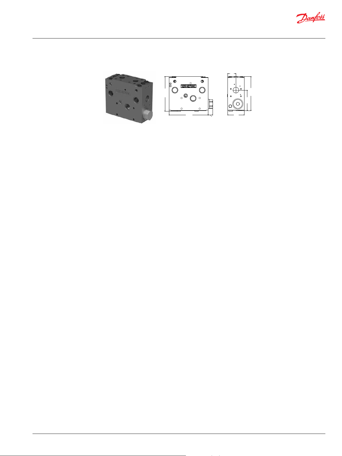
230
83.5
30
P109176
Technical Information
PVG 128/256 Technical Information
PVBS Main Spool
The PVG 128/256 main spools (PVBS) determines the flow out of the work section.
The PVBS main spool variants are based on a generic platform with a wide selection of additional
features, enabling you to tailor the PVBS to suit the demands of any hydraulic system and any function.
The PVBS main spool can be activated in three different ways:
•
Mechanically by a PVM lever
•
Electrically by either a PVE or a PVHC actuator
•
Hydraulically by a PVH actuator
All spools can be mechanically activated.
PVBS Main Spool
PVBS Main Spool dimensions
PVBS Main Spools variant overview
Flow control spools
•
Flow control spool closed neutral position
•
Flow control spool throttled open neutral position
•
Single acting cylinder flow control spool closed neutral position, flow control B port
•
Flow control spool closed neutral position with A-float
PVBS main spools product details
Technical data
Oil temperature Recommended 30 to 60°C [86 to 140°F]
Ambient temperature Recommended -30 to 60°C [-22 to 140°F]
Oil viscosity Operating range 12 to 75 mm2/s [65 to 347 SUS]
Oil contamination
according to ISO 4406
Minimum -30°C [-22°F]
Maximum 90° [194°F]
Minimum 4 mm2/s [39 SUS]
Maximum 460 mm2/s [2128 SUS]
Maximum 23/19/16
©
Danfoss | July 2021 BC220686485279en-000510 | 49
Page 50

A
P
25
50
75
100
125
150
175
200
225
250
275
300
325
[l/min] [US gal/min]
[mm]
PVM
0
1
2
3
4
5
67
[in]
PVM
00.040.08
0.120.160.20
0.240.28
PVEH
U
s
U
DC
0.50.45
0.4
0.350.3
8
0.31
0.25
910
350
375
400
0.350.39
5
10
15
20
25
30
35
40
45
50
55
60
65
70
75
80
85
90
95
100
105
BP
[mm]
PVM
109
8
765
[in]
PVM
0.390.350.310.280.240.20
PVEH
U
s
U
DC
0.70.650.60.55
4
0.16
0.5
3210
0.120.080.040
0.75
425
450
475
500
110
115
120
125
130
PVEH-U
5.0
2.5
PVEH-U
5.0
7.5
[V]
[V]
A
B
C
D
E
F
G
H
A
B
C
D
E
F
G
H
Technical Information
PVG 128/256 Technical Information
PVBS Main Spool
Progressive Oil Flow as Function of Spool Travel
50 | © Danfoss | July 2021 BC220686485279en-000510
Page 51

504540353025
20
15105
0
70
656055
Q
Q
1086420 1412 18
16
250
225
200
175
150
125
100
75
50
25
0
350
325
300
275
P
2500
2000
1500
1000
500
0
3500
3000
4000
5000
4500
A/B to T
[psi] [bar]
[l/min]
[US gal/min]
P109253
A
P
25
50
75
100
125
150
175
200
225
250
275
300
325
[l/min]
[US gal/min]
[mm]
PVM
01234567
[in]
PVM
00.040.080 .120.160.200.240 .28
8
0.31
9101112
350
375
400
0.350.390.430.47
5
10
15
20
25
30
35
40
45
50
55
60
65
70
75
80
85
90
95
100
105
A
B
C
D
E
F
F BP
[mm]
PVM
10
9
8765
[in]
PVM
0.390.350.310.280.240.20
4
0.16
3210
0.12
0.080 .04
A
B
C
D
E
F
G
PVH
15
bar
7
9
11
13
5
PVH
5791115
13
bar
17
PVH
218
psi
102
131
160
189
73
PVH
73102
131
160218
189
psi
247
Technical Information
PVG 128/256 Technical Information
PVBS Main Spool
Pressure drop for open spool in neutral position
Progressive oil flow characteristic of spool with A-float
PVS Main spools part numbers
©
Danfoss | July 2021 BC220686485279en-000510 | 51
Page 52

P109177
P109178
Technical Information
PVG 128/256 Technical Information
PVBS Main Spool
Flow control spools
Flow control spool closed neutral position
Schematic
Symmetric flow control spools
Part number
11177686 PVE 65 [17.17] 65 [17.17] 65 [17.17] 65 [17.17]
11177738 PVE 95 [25.10] 95 [25.10] 95 [25.10] 95 [25.10]
11177750 PVE 130 [34.34] 130 [34.34] 130 [34.34] 130 [34.34]
11177448 PVE 180 [47.55] 180 [47.55] 180 [47.55] 180 [47.55]
11177798 PVE 240 [63.40] 240 [63.40] 240 [63.40] 240 [63.40]
11178733 PVE 320 [84.54] 320 [84.54] 320 [84.54] 320 [84.54]
11177058* PVE 400 [105.67] 400 [105.67] 400 [105.67] 400 [105.67]
11184159 PVH/PVHC 65 [17.17] 65 [17.17] 65 [17.17] 65 [17.17]
11184846 PVH/PVHC 95 [25.10] 95 [25.10] 95 [25.10] 95 [25.10]
11182643 PVH/PVHC 130 [34.34] 130 [34.34] 130 [34.34] 130 [34.34]
11182640 PVH/PVHC 180 [47.55] 180 [47.55] 180 [47.55] 180 [47.55]
11182638 PVH/PVHC 240 [63.40] 240 [63.40] 240 [63.40] 240 [63.40]
11182635 PVH/PVHC 320 [84.54] 320 [84.54] 320 [84.54] 320 [84.54]
11182621
*
Up to 500 l/min in combination with PVB 256 3-way Turbo Compensator feature
Actuation Flow - l/min (US gal/min)
A→T P→A P→B B→T
*
PVH/PVHC 400 [105.67] 400 [105.67] 400 [105.67] 400 [105.67]
Asymmetric spools
Part number
**
**
Please contact your Danfoss Power Solutions representative if one of these variants is needed.
Actuation Flow - l/min (US gal/min)
A→T P→A P→B B→T
PVH/PVHC 65 [17.17] 65 [17.17] 130 [34.34] 130 [34.34]
PVH/PVHC 95 [25.10] 95 [25.10] 180 [47.55] 180 [47.55]
PVH/PVHC 130 [34.34] 130 [34.34] 240 [63.40] 240 [63.40]
PVH/PVHC 180 [47.55] 180 [47.55] 320 [84.54] 320 [84.54]
PVH/PVHC 240 [63.40] 240 [63.40] 400 [105.67] 400 [105.67]
Flow control spool throttled open neutral position
Schematic
52 | © Danfoss | July 2021 BC220686485279en-000510
Page 53

P109179
Technical Information
PVG 128/256 Technical Information
PVBS Main Spool
Symmetric flow control spools
Part number
1
11182537 PVE 95 [25.10] 95 [25.10] 95 [25.10] 95 [25.10]
11178290 PVE 130 [34.34] 130 [34.34] 130 [34.34] 130 [34.34]
11178310 PVE 180 [47.55] 180 [47.55] 180 [47.55] 180 [47.55]
11182619 PVE 240 [63.40] 240 [63.40] 240 [63.40] 240 [63.40]
11182618 PVE 320 [84.54] 320 [84.54] 320 [84.54] 320 [84.54]
11182617
(1) PVH/PVHC 65 [17.17] 65 [17.17] 65 [17.17] 65 [17.17]
11183604 PVH/PVHC 95 [25.10] 95 [25.10] 95 [25.10] 95 [25.10]
11183602 PVH/PVHC 130 [34.34] 130 [34.34] 130 [34.34] 130 [34.34]
11183441 PVH/PVHC 180 [47.55] 180 [47.55] 180 [47.55] 180 [47.55]
11178318 PVH/PVHC 240 [63.40] 240 [63.40] 240 [63.40] 240 [63.40]
11180718 PVH/PVHC 320 [84.54] 320 [84.54] 320 [84.54] 320 [84.54]
11178984 (2) PVH/PVHC 400 [105.67] 400 [105.67] 400 [105.67] 400 [105.67]
1
Please contact your Danfoss Power Solutions representative if one of these variants is needed.
2
Up to 500 l/min in combination with PVB 256 3-way Turbo Compensator feature
2
Actuation Flow - l/min (US gal/min)
A→T P→A P→B B→T
PVE 65 [17.17] 65 [17.17] 65 [17.17] 65 [17.17]
PVE 400 [105.67] 400 [105.67] 400 [105.67] 400 [105.67]
Asymmetric flow control spools
Part number
**
**
Please contact your Danfoss Power Solutions representative if one of these variants is needed.
Actuation Flow - l/min (US gal/min)
A→T P→A P→B B→T
- 65 [17.17] 65 [17.17] 130 [34.34] 130 [34.34]
- 95 [25.10] 95 [25.10] 180 [47.55] 180 [47.55]
- 130 [34.34] 130 [34.34] 240 [63.40] 240 [63.40]
- 180 [47.55] 180 [47.55] 320 [84.54] 320 [84.54]
- 240 [63.40] 240 [63.40] 400 [105.67] 400 [105.67]
Single acting cylinder flow control spool closed neutral position, flow control B port
Schematic
Part number
1
(1) PVE - - 95 [25.10] 95 [25.10]
(1) PVE - - 130 [34.34] 130 [34.34]
(1) PVE - - 180 [47.55] 180 [47.55]
(1) PVE - - 240 [63.40] 240 [63.40]
(1) PVE - - 320 [84.54] 320 [84.54]
2
(1)
Actuation Flow - l/min (US gal/min)
A→T P→A P→B B→T
PVE - - 65 [17.17] 65 [17.17]
PVE - - 400 [105.67] 400 [105.67]
©
Danfoss | July 2021 BC220686485279en-000510 | 53
Page 54

P109180
Technical Information
PVG 128/256 Technical Information
PVBS Main Spool
Part number
(1) PVH/PVHC - - 65 [17.17] 65 [17.17]
(1) PVH/PVHC 95 [25.10] 95 [25.10]
(1) PVH/PVHC - - 130 [34.34] 130 [34.34]
(1) PVH/PVHC - - 180 [47.55] 180 [47.55]
(1) PVH/PVHC - - 240 [63.40] 240 [63.40]
(1) PVH/PVHC - - 320 [84.54] 320 [84.54]
(1)(2) PVH/PVHC - - 400 [105.67] 400 [105.67]
1
Please contact your Danfoss Power Solutions representative if one of these variants is needed.
2
Up to 500 l/min in combination with PVB 256 3-way Turbo Compensator feature
Actuation Flow - l/min (US gal/min)
A→T P→A P→B B→T
Flow control spool closed neutral position with A-float
Schematic
Symmetric flow control spools
Part number
1
(1) PVE 95 [25.10] 95 [25.10] 95 [25.10] 95 [25.10]
(1) PVE 130 [34.34] 130 [34.34] 130 [34.34] 130 [34.34]
(1) PVE 180 [47.55] 180 [47.55] 180 [47.55] 180 [47.55]
(1) PVE 240 [63.40] 240 [63.40] 240 [63.40] 240 [63.40]
(1) PVE 320 [84.54] 320 [84.54] 320 [84.54] 320 [84.54]
(1) PVH/PVHC 65 [17.17] 65 [17.17] 65 [17.17] 65 [17.17]
(1) PVH/PVHC 95 [25.10] 95 [25.10] 95 [25.10] 95 [25.10]
(1) PVH/PVHC 130 [34.34] 130 [34.34] 130 [34.34] 130 [34.34]
(1) PVH/PVHC 180 [47.55] 180 [47.55] 180 [47.55] 180 [47.55]
(1) PVH/PVHC 240 [63.40] 240 [63.40] 240 [63.40] 240 [63.40]
(1) PVH/PVHC 320 [84.54] 320 [84.54] 320 [84.54] 320 [84.54]
1
Please contact your Danfoss Power Solutions representative if one of these variants is needed.
Actuation Flow - l/min (US gal/min)
A→T P→A→F P→B B→T
PVE 65 [17.17] 65 [17.17] 65 [17.17] 65 [17.17]
54 | © Danfoss | July 2021 BC220686485279en-000510
Page 55

109.7 [4.32]
113 [4.45]
133.5 [5.26]
Weight: 1.5 kg [3.3 lbs]
Technical Information
PVG 128/256 Technical Information
PVM Manual Activation
PVM Lever dimensions
The PVM manual activation cover is intended for use on any work section where the operator has to have
the ability to interact with the spool manually.
The adjustment screws are intended for limiting the spool travel and thereby the maximum achievable
flow.
©
Danfoss | July 2021 BC220686485279en-000510 | 55
Page 56

37°
30°
37°
30°
30°
30°
30°
30°
With float
Standard
Technical Information
PVG 128/256 Technical Information
PVM Manual Activation
PVM Technical Data
Handle Installation
Technical data
Spool displacement Torque
From neutral position PVM+PVMD 12 N·m 106 lb·in
PVM+PVE 12 N·m 106 lb·in
PVM+PVH 30 N·m 265 lb·in
Max. spool travel PVM+PVMD 30 N·m 265 lb·in
PVM+PVE 30 N·m 265 lb·in
PVM+PVH 91 N·m 805 lb·in
Standard Control Range 30°
Control lever range + float position 37°
Part numbers for PVM Manual Activation
Part number Material Adjustment screws Lever base and lever B-port Gauge
11176644 Cast iron - Yes No
11175317 Cast iron Yes Yes G1/8" BSP
11176635 Cast iron Yes Yes 3/8"-24 UNF
56 | © Danfoss | July 2021 BC220686485279en-000510
Page 57

33 43.7
100
65
Weight: 1.9 kg [4.2 lbs]
AP
25
50
75
100
125
150
175
200
225
250
275
300
325
[l/min] [US gal/min]
[mm]
PVM
01234567
[in]
PVM
00.040.080. 120.160.200. 240.28
PVH
bar
bar
5791113
8
0.31
15
910
350
375
400
0.350.39
5
10
15
20
25
30
35
40
45
50
55
60
65
70
75
80
85
90
95
100
105
BP
[mm]
PVM
1098765
[in]
PVM
0.390.350.310.280. 240.20
PVH
131197
4
0.16
5
321
0
0.120.080.04
0
15
425
450
475
500
110
115
120
125
130
A
B
C
D
E
F
G
H
A
B
C
D
E
F
G
H
bar
bar
PVH
psi
psi
73102131160189
218
PVH
189160131102
73
218
psi
psi
P109247
Technical Information
PVG 128/256 Technical Information
PVH Hydraulic Actuation
PVH dimensions
The PVH hydraulic activation cover is intended for use on any work section where the operator wants to
have a possibility to interact with the main spool via a hydraulic joystick.
Inlet with Hydraulic Pilot Pressure is needed.
©
Danfoss | July 2021 BC220686485279en-000510 | 57
Page 58

Technical Information
PVG 128/256 Technical Information
PVH Hydraulic Actuation
PVH Technical Data
Technical data
Main Spool Spring control pressure range 5 – 15 bar [73 – 218 psi]
Pilot oil pressure range between 20 and 25 bar 20 – 25 bar [290 – 362 psi]
Max. pressure on port T (the hydraulic remote control
lever should be connected directly to tank).
Part numbers for PVH Hydraulic Actuation
Part number Material Connection
11187777 Aluminum G1/4" BSP
11187776 Aluminum 9/16"-18 UNF
10 bar [145 psi]
58 | © Danfoss | July 2021 BC220686485279en-000510
Page 59

65
100
43.7100.5
Weight: 2.6 kg [5.7 lbs]
P109249
Technical Information
PVG 128/256 Technical Information
PVHC Electro-Hydraulic Actuator type
The PVHC is an electrical actuator module for main spool control.
The PVHC control is done by dual Pulse Width Modulated (PVM) high current supply 100-400 Hz PWM
control signals.
The hysteresis is affected by viscosity, friction, flow forces, dither frequency and modulation frequency.
The spool position will shift when conditions are changed such as temperature change.
Inlet with Hydraulic Pilot Pressure is needed.
Dither frequency with a certain amplitude is needed for optimal application performance.
Schematic
©
Danfoss | July 2021 BC220686485279en-000510 | 59
Page 60

AP
1
2
3
4
5
6
7
8
9
10
0
0
200
100
400
200
600
300
800
400
1000
500
BP
800
400
600
300
400
200
200
100
1000
500
[Current in mA][Current in mA]
@12V
@24V
@12V
@24V
1600
800
1400
700
1200
600
1200
600
1600
800
1400
700
Spool stroke, mm
PVHC characteristics – Spool stroke vs current
Ideal curve
Hysteresis
P109250
Technical Information
PVG 128/256 Technical Information
PVHC Electro-Hydraulic Actuator type
PVHC Technical Data
Technical data
Main Spool Spring control pressure
range
Pilot oil pressure range between 20
and 25 bar
Max. pressure on port T 10 bar [145 psi]
PVHC 12 Volt Current Input 0-1500 mA
PVHC 24 Volt Current Input 0-750 mA
Ambient Temperature Range -30°C to 80°C [-22 °F to 176°F]
Medium Temperature Range -20°C to 80°C [-4 °F to 176°F]
Oil contamination according to ISO
4406 Maximum
5-15 bar [73-218 psi]
20-25 bar [290-362 psi]
23/19/16
Part numbers for PVHC Electro-Hydraulic Actuator types
Part number Power supply Connector type
11187757 12V AMP
11187772 12V DEUTSCH
11187774 24V AMP
11187775 24V DEUTSCH
60 | © Danfoss | July 2021 BC220686485279en-000510
Page 61

100
65
32 17
14
Weight: 1.5 kg [3.3 lbs]
Technical Information
PVG 128/256 Technical Information
PVMD Cover Manual Actuation Only
PVMD dimensions
The PVMD cover is used when work section is purely mechanical activated.
PVMD Part Numbers
Part numbers for PVMD Covers
Part number Material
11187779 Aluminum
©
Danfoss | July 2021 BC220686485279en-000510 | 61
Page 62

Technical Information
PVG 128/256 Technical Information
PVE Electrical Actuator
PVE Series 7 Electrical Actuator
The analog PVE Series 7 is an electro-hydraulic actuator used to control a single work section of a PVG
proportional valve group. The PVE Series 7 actuator program includes variants with different
performance levels and features for PVG 128/256.
The actuator positions the main spool in a PVG work section in order to control either the flow or the
pressure of the oil distributed to/from the work function. The control signal to the actuator is an analog
voltage signal, enabling the user to operate the work function remotely by means of a joystick, a
controller or the similar.
The electro-hydraulic solenoid valve bridge of the actuator is available in different designs utilizing
different regulation principles, depending on performance variant. The actuator positions the main spool
by distributing pilot oil pressure to either side of it, pressurizing one side by pilot pressure while relieving
the opposite side to tank and vice versa, as illustrated below. All proportional actuators feature a closedloop spool control and continuous fault monitoring.
The analog PVE Series 7 actuator program for PVG 128/256 features two different main hydraulic
principle variants (PVEO and PVEH). The different hydraulic principles combined with the different
solenoid valve regulation principles determine whether the actuator controls the spool proportionally
according to a demand signal or ON/OFF according to a voltage signal. The voltage control characteristic
of the PVE Series 7 actuators is shown in the figure below to the left.
PVG 256 with PVEO
62 | © Danfoss | July 2021 BC220686485279en-000510
Page 63
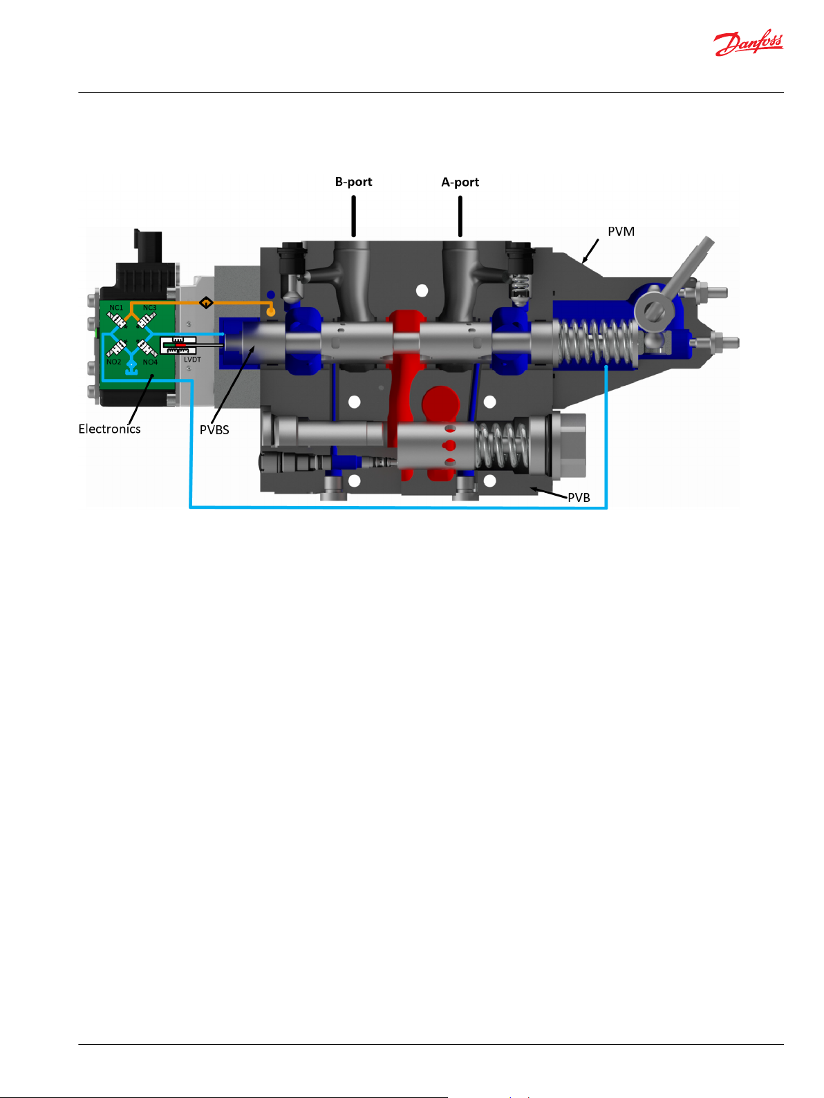
Technical Information
PVG 128/256 Technical Information
PVE Electrical Actuator
PVG 256 with PVEH
©
Danfoss | July 2021 BC220686485279en-000510 | 63
Page 64

P109195
P109198
Technical Information
PVG 128/256 Technical Information
PVE Variant Overview
PVE Variant Overview
PVEO Series 7 PVEH Series 7
Symbol Description
PVEO
ON/OFF voltage control for non-proportional functions.
Neutral position or max. spool stroke according to control
•
signal
Variants available with 12 V dc or 24 Vdc supply voltage
•
Variants available with DEUTSCH or DIN/Hirschmann
•
connectors
To be used with standard PVE pilot oil pressure of 13.5 bar
•
LED only indicating Power ON or Power OFF
•
PVEH
Proportional spool control for functions with high performance
and reaction demands.
All variants with 11-32 Vdc multi-voltage power supply
•
Variants available with DEUTSCH or DIN/Hirschmann
•
connectors
To be used with standard PVE pilot oil pressure of 13.5 bar
•
All variants with LED indicating error state and active or
•
passive fault monitoring
Variants available with Float (-F) or 0-10 V dc control signal (-
•
U) functionality
PVEO
64 | © Danfoss | July 2021 BC220686485279en-000510
Page 65

21
0
Pp
SV2SV1
LED Circuit
LED
A
B
Technical Information
PVG 128/256 Technical Information
PVE Variant Overview
PVEO
The PVEO actuator is a non-proportional ON/OFF control actuator with open-loop spool control primarily
used to control simple ON/OFF work functions where a proportional control of speed or oil flow is not a
requirement
PVEO
PVEO functionality
The standard PVEO functionality includes the simplest electric circuit of the PVG 128/256 actuator
program, using a fixed 12 Vdc or 24 Vdc supply voltage or signal voltage and a simple LED circuit to
control the LED light indicating Power ON/OFF.
An energization of solenoid valve SV1 and a simultaneous de-energization of SV2 will cause the main
spool to move to the right direction and vice versa. If both SV1 and SV2 are energized or de-energized
simultaneously, the main spool stays locked in its neutral position.
©
Danfoss | July 2021 BC220686485279en-000510 | 65
Page 66

P109195
133 [5.24]
65 [2.56]
102 [4.0]
P109127
Technical Information
PVG 128/256 Technical Information
PVE Variant Overview
PVEO Schematics and Dimensions
PVEO schematics
PVEO
Dimensions
PVEO Connector height
DEU = 24 mm [0.94 in]
DIN = 13 mm [0.51 in]
Weight: 2 kg [4.4 lbs]
PVEO Technical Data
Control Specification
Description Type Value
Supply Voltage (Udc) Rated 12 Vdc 24 Vdc
Range 11 to 15 Vdc 22 to 30 Vdc
Max. ripple 5%
Current Consumption Typical 708 mA 361 mA
Minimum 430 mA 220 mA
Maximum 944 mA 482 mA
Operating Conditions
Description Type Value
Pilot Pressure Nominal 13.5 bar [196 psi]
Minimum 10.0 bar [145 psi]
66 | © Danfoss | July 2021 BC220686485279en-000510
Maximum 15.0 bar [218 psi]
Page 67

100
0
Time
T0 T1
T2
P109128
Spool position
Demand Signal (Us)
Supply Voltage (U dc)
Spool pos. [%]
Technical Information
PVG 128/256 Technical Information
PVE Variant Overview
Operating Conditions (continued)
Description Type Value
Oil Consumption Neutral 0.0 l/min [0.0 gal/min]
Max T-port pressure Static 25 bar [365 psi]
Max T-port pressure Intermittent 40 bar [580 psi]
Storage Temperature Ambient -50 to +90°C [-58 to +194°F]
Operating Temperature Ambient -40 to +90°C [-40 to +194°F]
Oil Viscosity Operating range 12 to 75 cSt [65 to 347 SUS]
Oil Cleanliness Maximum 18/16/13 (according to ISO 4406)
LED characteristic
Color LED characteristic Description
Green constant Power ON
Locked position 0.0 l/min [0.0 gal/min]
Actuating 0.9 l/min [0.24 gal/min]
Minimum 4 cSt [39 SUS]
Maximum 460 cSt [2128 SUS]
PVEO 128/256 Reaction Times
PVEO
Reaction PVG128 PVG 256
T1 A-port – Neutral to maximum spool stroke @ Constant Udc 375 ms 375 ms
T1 B-port – Neutral to maximum spool stroke @ Constant Udc 520 ms 520 ms
T2 A-port – Maximum spool stroke to neutral @ Constant Udc 350 ms 350 ms
T2 B-port – Maximum spool stroke to neutral @ Constant Udc 600 ms 600 ms
PVEO Variants for PVG
PVG 128/256 Variants
Part number Type
11186328 PVEO 1x4 DEU 67 12 Vdc Standard
11186330 PVEO 1x4 DEU 67 24 Vdc Standard
Connector
IP Udc
Functionality
©
Danfoss | July 2021 BC220686485279en-000510 | 67
Page 68

21
0
Pp
Micro-
controller
Power
Supply
F
LED
Error
U
Us
Udc
NC1 NC3
LVDT
NO2 NO4
Special
Features
Technical Information
PVG 128/256 Technical Information
PVE Variant Overview
PVG 128/256 Variants (continued)
Part number Type
11186331 PVEO 1x4 DIN 65 12 Vdc Standard
11186342 PVEO 1x4 DIN 65 24 Vdc Standard
PVEH
PVEH Overview
The PVEH actuator is a proportional control actuator with closed-loop spool control primarily used to
control work functions with high performance requirements.
The PVEH functionality includes an electric circuit with a closed-loop logic. An embedded microcontroller
processes the signal voltage and the LVDT feedback signal and regulates the solenoid valves accordingly.
Features such as active or passive fault monitoring, LED indicating fault state, error output pin and Power
Save are all default PVEH features.
A continuous modulation of solenoid valves NC1 and NO4 together, with a simultaneous energization of
NO2 and de-energization of NC3, causes the main spool to move to the right direction and vice versa.
When the main spool is stroked to the far right, a simultaneous energization of both NO2 and NO4 and
de-energization of both NC1 and NC3 locks the main spool in its stroked position. An emergency stop
activated when the spool is stroked will cause all solenoid valves to de-energize causing the main spool
to move back to its neutral position by means of the main spool neutral spring and the hydraulic
principle.
Connector
IP Udc
Functionality
Functionality
PVEH
68 | © Danfoss | July 2021 BC220686485279en-000510
Page 69

P109198
102 [4.01]
65 [2.56]
121 [4.76]
P109158
Technical Information
PVG 128/256 Technical Information
PVE Variant Overview
PVEH Schematics and Dimensions
Schematics
PVEH
Dimensions
PVEH Connector height
DEU = 24 mm [0.94 in]
DIN = 13 mm [0.51 in]
2 kg [4.4]
PVEH Technical Data
Control Specification
Description Type Value
Supply Voltage (UDC) Rated Range 11 to 32 V
Max. ripple 5%
Signal Voltage PWM (US) Neutral US = 0.5 UDC = 50% DUT
Q: P to A US = (0.5 to 0.25) UDC = 50% to 25% DUT
Q: P to B US = (0.5 to 0.75) UDC = 50% to 75% DUT
Input Impedance Rated 12 kΩ
Input Capacitance Rated 1 nF
©
Danfoss | July 2021 BC220686485279en-000510 | 69
DC
Page 70
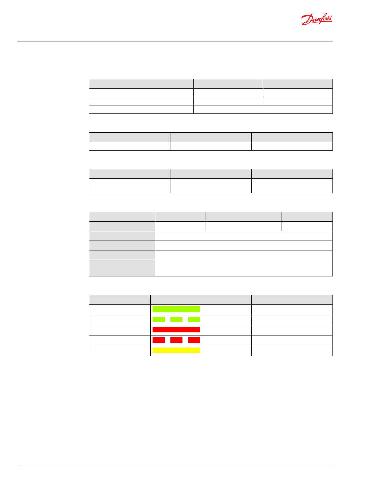
Technical Information
PVG 128/256 Technical Information
PVE Variant Overview
Current consumption
Description @ 12 V
PWM Frequency (US) recommended > 1000 Hz > 1000 Hz
Current Consumption 540 mA 270 mA
Power Save 25 mA @ UDC = 32 V
Pilot pressure
Minimum Nominal Maximum
10.0 bar [145 psi] 13.5 bar [196 psi] 15.0 bar [218 psi]
Fluid consumption
Neutral Locked position Actuating
0.0 l/min 0.0 l/min 0.7 l/min
Technical specification
Parameter Minimum Recommended range Maximum
Fluid viscosity
Fluid cleanliness
Storage temperature
Operating temperature
Max. T-port pressure
static / intermittent
DC
4 mm2/s [39 SUS] 12 to 75 mm2/s [65 to 347 SUS] 460 mm2/s [2128 SUS]
18/16/13 (according to ISO 4406)
Ambient: -50 to 90°C [-58 to 194°F]
Ambient: -40 to 90°C [-40 to 194°F]
25 / 40 bar
[365 / 580 psi]
@ 24 V
DC
DC
[0.18 US gal/min]
LED Characteristic
Color LED Characteristic Description
Green constant No error – Actuating
Green flashing @ 1.5 Hz Neutral – Power save
Red constant Internal error
Red flashing @ 1.5 Hz External or Float error
Yellow Disable mode
70 | © Danfoss | July 2021 BC220686485279en-000510
Page 71

100
0
Time
T0 T1
T2
P109128
Spool position
Demand Signal (Us)
Supply Voltage (U dc)
Spool pos. [%]
Us [%]
100
0
Spool Position [%]
100
(0.75 ∙ U dc)
BP
h
50
(0.50 ∙ U dc)
vFixed pos.
Spool Position
Technical Information
PVG 128/256 Technical Information
PVE Variant Overview
PVEH for PVG 128/256 Reaction Times
PVEH
Reaction PVG 128/256
T0 – Boot up 80 ms
T1 – Neutral to maximum spool stroke @ Power ON 400 ms
T2 – Maximum spool stroke to neutral @ Power OFF 300 ms
T1 – Neutral to maximum spool stroke @ Constant Udc 380 ms
T2 – Maximum spool stroke to neutral @ Constant Udc 270 ms
T0 + Deadband 130 ms
For more information on reaction times, see Reaction Times.
PVEH Hysteresis and Ripple
Spool position vs. supply (%)
Description Type PVEH
Hysteresis (h) Rated [%] <2
Steady state ripple @ fixed Us (v) Rated [mm] 0.0
©
Danfoss | July 2021 BC220686485279en-000510 | 71
Page 72

Technical Information
PVG 128/256 Technical Information
PVE Variant Overview
PVEH Variants for PVG
PVG 128/256 variants
Part number Type
11186325 PVEH 1x4 DEU 67 Passive Standard
11186326 PVEH 1x4 DEU 67 Active Standard
11186321 PVEH 1x4 DIN 65 Passive Standard
11186322 PVEH 1x4 DIN 65 Active Standard
Connector
IP
Fault monitoring
Functionality
72 | © Danfoss | July 2021 BC220686485279en-000510
Page 73

2
3
4
1
1
2
3 4
5
6
1 2
3
4
1
2 3
41
2 3
4
Technical Information
PVG 128/256 Technical Information
Connector Overview
Connector Overview
PVEO 4-pin Connector
Pinout Pin 1 Pin 2 Pin 3 Pin 4
1x4 DEUTSCH UDC_A GND GND UDC_B
1x4 DIN UDC_A UDC_B - GND
PVEH/PVEH-U
Pinout Pin 1 Pin 2 Pin 3 Pin 4
1x4 DEUTSCH U
1x4 DIN U
PVEH-FLA 6-pin Connector
Pinout Pin 1 Pin 2 Pin 3 Pin 4 Pin 5 Pin 6
1x6 DEUTSCH U
S
DC
S
Error Float - GND U
Error GND U
U
S
Error GND
DC
DC
Connector diagrams
1x4 DEUTSCH
PVE Connector Direction
1x4 DIN
1x6 DEUTSCH
©
Danfoss | July 2021 BC220686485279en-000510 | 73
Page 74

Technical Information
PVG 128/256 Technical Information
Fault Monitoring and Reaction
All proportional control PVG 128/256 actuators feature:
Integrated fault monitoring
•
Detecting spool stroke inconsistencies
•
Detecting internal hardware defects
•
Detecting demand signal inconsistencies
•
Fault reaction depending on the type of fault monitoring
•
Generic
‒
Specific
‒
Passive and active fault monitoring refers to whether or not the actuator is reacting on the error when it
is detected.
Active fault monitoring
No matter what kind of error is detected, the solenoid valves will be disabled and the operation that the
valves/spool controls will stop immediately and spool will go to neutral position. Active fault monitoring
keeps a “memory” of the error, even if it is no longer registered. The active fault monitoring does not have
Auto Recovery because of this “memory” and a reboot/restart will therefore be required to reactivate the
solenoid valves.
With an active fault monitoring the following scenarios will take place when an error is detected/occurs:
•
The LED light will switch from green to red and the error pin output will go high
•
The solenoid valves will be disabled and the operation that the valves/spool controls will stop
immediately
•
The active fault monitoring does not have Auto Recovery, so when the error is fixed/no longer is
registered a reboot/restart of the PVE is required to reactivate it.
Generic Fault Reaction
Passive fault monitoring
Passive fault monitoring does not disable the solenoid valves when an error is detected. It will continue
to operate despite that an error was detected. When the error no longer is registered the passive fault
monitoring will “forget” the error and continue as if the error was never there.
With a passive fault monitoring the following conditions will happen when an error is detected/occurs:
The LED light will switch from green to red and the error pin output will go high
•
The solenoid valves will continue operating at the set point given at the time of the error
•
Only exception is if the error is caused by the supply voltage (UDC) being either above or below
‒
the allowed range or if the temperature measured on the internal electronics board is higher than
allowed. In these cases, the solenoid valves will be disabled.
All PVE actuators with fault monitoring are triggered by the following main events:
Control Signal Monitoring
Transducer/LVDT Supervision
Supervision of Spool Position
The Control signal voltage (US) is continuously monitored.
The permissible range is between 15% and 85% of the supply voltage (UDC).
Outside this range the PVE will switch into an error state. A disconnected U
pin (floating) is recognized as a neutral set point.
The internal LVDT wires are monitored. If the signals are interrupted or short-
circuited, the PVE will switch into an error state.
The actual position must always correspond to the demanded position (US).
If the actual spool position is further out from neutral than the demanded
spool position or in opposite direction, the PVE will switch into an error state.
Spool position closer to neutral and in same direction will not cause an error
state – the situation is considered in control.
S
74 | © Danfoss | July 2021 BC220686485279en-000510
Page 75

Technical Information
PVG 128/256 Technical Information
Fault Monitoring and Reaction
Float Position Monitoring
Float position must be entered or left within a time limit.
A too high delay on the 1x6 pin float PVE will cause an error state – this is
relevant for the 1x6 pin PVEH-F actuators only.
Temperature Monitoring
When the temperature is too high the PVE LED will light constant red and
solenoid valves will be disabled.
PVEH Fault Reaction Overview
Description Monitoring LED Solenoid valves Error pin output Fault reaction
Spool not at
setpoint
Unable to reach
float position
*
Active
Disabled High 500
Passive - High 250
*
Active
Disabled High 1000
Passive - High 1000
U dc > max. Active Disabled - -
Passive Disabled - -
U dc < min. Active Disabled - -
Passive Disabled - -
Us out of range Active
*
Disabled High 500
Passive - High 250
LVDT error Active
*
Disabled High 500
Passive - High 250
Temp > max. Active
*
Disabled High 250
Passive Disabled High 250
*
Does not have Auto Recovery
time (ms)
PVEH
©
Danfoss | July 2021 BC220686485279en-000510 | 75
Page 76

Time
Udc
Udc
2
GND
V
1
V
2
t
1
T
P109152
Demand Signal (Us)
Supply Voltage (Udc)
Supply Voltage (Udc)
Technical Information
PVG 128/256 Technical Information
Functionality Overview
Standard and Fixed US 0-10 Vdc
All standard proportional actuator variants PVEH can be controlled by an analog signal voltage (Us) or a
PWM controlled signal voltage (Us) proportional to the supply voltage (Udc).
PVEO
Description Type Value
Supply voltage (Udc) Rated 12 Vdc 24 Vdc
PVEH
Description Type Value
Supply voltage (Udc) Rated 11 to 32 Vdc
Signal voltage (Us) Neutral Us = 0.5 ∙ Udc
Range 11 to 15 Vdc 22 to 30 Vdc
Max. ripple 5%
Range 11 to 32 Vdc
Max. ripple 5%
Q: P to A US = (0.5 to 0.25) ∙ Udc
Q: P to B US = (0.5 to 0.75) ∙ Udc
The PVEH-U variants are controlled by a fixed 0-10 Vdc signal voltage (Us), directly compatible with
standard PLC control.
PVEH-U
Description Type Value
Supply voltage (Udc) Rated 11 to 32 Vdc
Range 11 to 32 Vdc
Max. ripple 5%
Signal voltage (Us) Neutral Us = 5 V
Q: P to A 5 V to 2.5 V
Q: P to B 5 V to 7.5 V
PWM Voltage Control
The PVEH actuator variants can be controlled by a PWM controlled signal voltage (Us) proportional to the
supply voltage (Udc).
The V1 and V2 must be symmetrical around Udc/2 and V1 must be equal to or less than Udc.
76 | © Danfoss | July 2021 BC220686485279en-000510
Page 77

Technical Information
PVG 128/256 Technical Information
Functionality Overview
PVEH Control specification
Description Type Value
Supply Voltage (Udc) Rated 11 to 32 Vdc
Signal Voltage PWM (Us) Neutral Us = 50% DUT
PWM Frequency (Us) Recommended > 1000 Hz
Range 11 to 32 Vdc
Max. ripple 5%
Q: P to A Us = 50% to 25% DUT
Q: P to B Us = 50% to 75% DUT
©
Danfoss | July 2021 BC220686485279en-000510 | 77
Page 78

AP
25
50
75
100
125
150
175
200
225
250
275
300
325
[l/min]
[mm]
PVM
0
1234
5
6
7
[in]
PVM
00.040.080.120.16
0.20
0.240.28
PVEH-FLA
U
s
U
DC
0.05
0.1
0.150.2
0.25
8
0.31
910
11
12
350
375
400
0.35
0.39
0.43
0.47
5
10
15
20
25
30
35
40
45
50
55
60
65
70
75
80
85
90
95
100
105
A
B
C
D
E
F
F
Technical Information
PVG 128/256 Technical Information
Functionality Overview
Float A-Port (-FLA)
The Float A-Port functionality enables the proportional PVEH-FLA actuator variants to enter the main
spool into a float position. The PVE actuators with Float A-Port functionality is compatible with the
dedicated main spools with electronic float in A-port.
PVE Type PVBS Type Standard Flow Control Float Control
PVEH-FLA (1x6 pin) Deadband 0.8 mm Us = (0.25 → 0.75) ∙ Udc U dc to dedicated float pin
Max. A-port flow 5.5 mm
(UF)
PVE Power Save
All proportional actuator variants feature a Power Save mode, de-energizing the solenoid valve bridge.
The Power Save mode is entered when the signal voltage (Us) and the LVDT spool position has been in
neutral for 750 ms. As soon as the signal voltage (Us) or the LVDT spool position is out of neutral the PVE
will leave its Power Save mode and re-energize the solenoid valve bridge as usual.
The Power Save mode results in increased power efficiency by reducing the current consumption of the
78 | © Danfoss | July 2021 BC220686485279en-000510
PVE actuators in neutral position. The Power Save mode has no effect on the performance of the PVE
actuator.
Page 79

21
0
Pp
Micro-
controller
Power
Supply
F
LED
Error
U
Us
Udc
NC1 NC3
LVDT
NO2 NO4
Special Features
Technical Information
PVG 128/256 Technical Information
Special Features
Dedicated Float Pin (UF)
The Dedicated Float Pin (UF) feature is related to the PVEH-FLA actuator variant enabling the user to
move the main spool into its float position by power. The PVEH-FLA uses 1x6 pin AMP orDEUTSCH
connectors.
•
Normal operation: Low or not connected
•
High Float
•
Input range: U
•
Max. voltage: 32 V
PVEH-FLA functionality diagram
DC
DC
Disable Mode
The PVEH-U actuator variants controlled by a fixed 0-10 VDC signal voltage (US), feature the ability to enter
a disable mode. This causes the counteracting force on the main spool created by the solenoid valve
bridge to deactivate, when using Manual OverRide (MOR).
The disable mode is entered by sending a signal voltage (Us) of 16.2% of 10 VDC when in Power Save.
©
Danfoss | July 2021 BC220686485279en-000510 | 79
Page 80

100
0
Time
T0 T1
T2
P109128
Spool position
Demand Signal (Us)
Supply Voltage (U dc)
Spool pos. [%]
Technical Information
PVG 128/256 Technical Information
Performance Overview
PVG 128/256 Reaction Times
Reaction
T0 – Boot-up [ms]
T1 – Neutral to max. spool stroke
T2 – Max. spool stroke to neutral
T1 – Neutral to max. spool stroke
T2 – Max. spool stroke to neutral
PVEO
Reaction PVG128 PVG 256
T1 A-port – Neutral to maximum spool stroke @ Constant
375 ms 375 ms
Udc
T1 B-port – Neutral to maximum spool stroke @ Constant
520 ms 520 ms
Udc
T2 A-port – Maximum spool stroke to neutral @ Constant
350 ms 350 ms
Udc
T2 B-port – Maximum spool stroke to neutral @ Constant
600 ms 600 ms
Udc
PVEH
Reaction PVG 128 PVG 256
T0 – Boot up 80 ms 80 ms
T1 – Neutral to maximum spool stroke @ Power ON 400 ms 380 ms
T2 – Maximum spool stroke to neutral @ Power OFF 300 ms 270 ms
T1 – Neutral to maximum spool stroke @ Constant Udc 320 ms 320 ms
T2 – Maximum spool stroke to neutral @ Constant Udc 250 ms 250 ms
T0 + Deadband 130 ms 130 ms
80 | © Danfoss | July 2021 BC220686485279en-000510
Page 81

Us [%]
100
0
Spool Position [%]
100
(0.75 ∙ U dc)
BP
h
50
(0.50 ∙ U dc)
vFixed pos.
Spool Position
Technical Information
PVG 128/256 Technical Information
Performance Overview
Hysteresis and Ripple
Type Hysteresis (h) Steady state ripple @ fixed Us (v)
PVEH 256 1.5 0.0
Rated [%] Rated [mm]
Oil Consumption
Type Neutral Locked position Actuating
[l/min]
PVEO 0.0 0.0 0.9
PVEH 0.0 0.0 0.7
©
Danfoss | July 2021 BC220686485279en-000510 | 81
Page 82

PVSI with or without LX connection
PVSI with P and T connections
PVGI Interface plate
Technical Information
PVG 128/256 Technical Information
PVSI/PVGI End and Interface Plates
The PVG PVGI Interface Plate act as an interface between the PVB 256/128 and PVB 32/16 basic modules
which enables you to build a combo valve with PVB 256/128/32/16.
Optional the PVSI End Plate features additional P and T connection to accommodate an additional 600
l/min pump flow.
The PVS end plate variants are based on a generic platform with a selection of additional features,
enabling you to tailor the PVSI/PVGI to suit the demands of any hydraulic system. Versions available with
LX connection, and P and T connections. PVSI and PVGI are all in cast iron.
The generic PVSI/PVGI End and Interface Plates platform includes the following main variants:
•
PVSI with or without LX-connection
•
PVSI with P and T connections
•
PVSI Interface plate
Technical data
Max. rated pressure P-port continuous 350 bar [5076 psi]
P-port intermittent 400 bar [5800 psi]
T-port static/dynamic 25/40 bar [363/580 psi]
Oil temperature Recommended 30 to 60°C [86 to 140°F]
Minimum -30°C [-22°F]
Maximum 90° [194°F]
Ambient temperature Recommended -30 to 60°C [-22 to 140°F]
Oil viscosity Operating range 12 to 75 mm2/s [65 → 347 SUS]
Minimum 4 mm2/s [39 SUS]
Maximum 460 mm2/s 23/19/16
Oil contamination
according to ISO 4406
Maximum 23/19/16
For more information about PVSI/PVGI End and Interface Plates, see:
PVSI with or without LX-connection on page 83
PVSI with P and T port connections on page 84
PVGI Interface Plate on page 85
82 | © Danfoss | July 2021 BC220686485279en-000510
Page 83
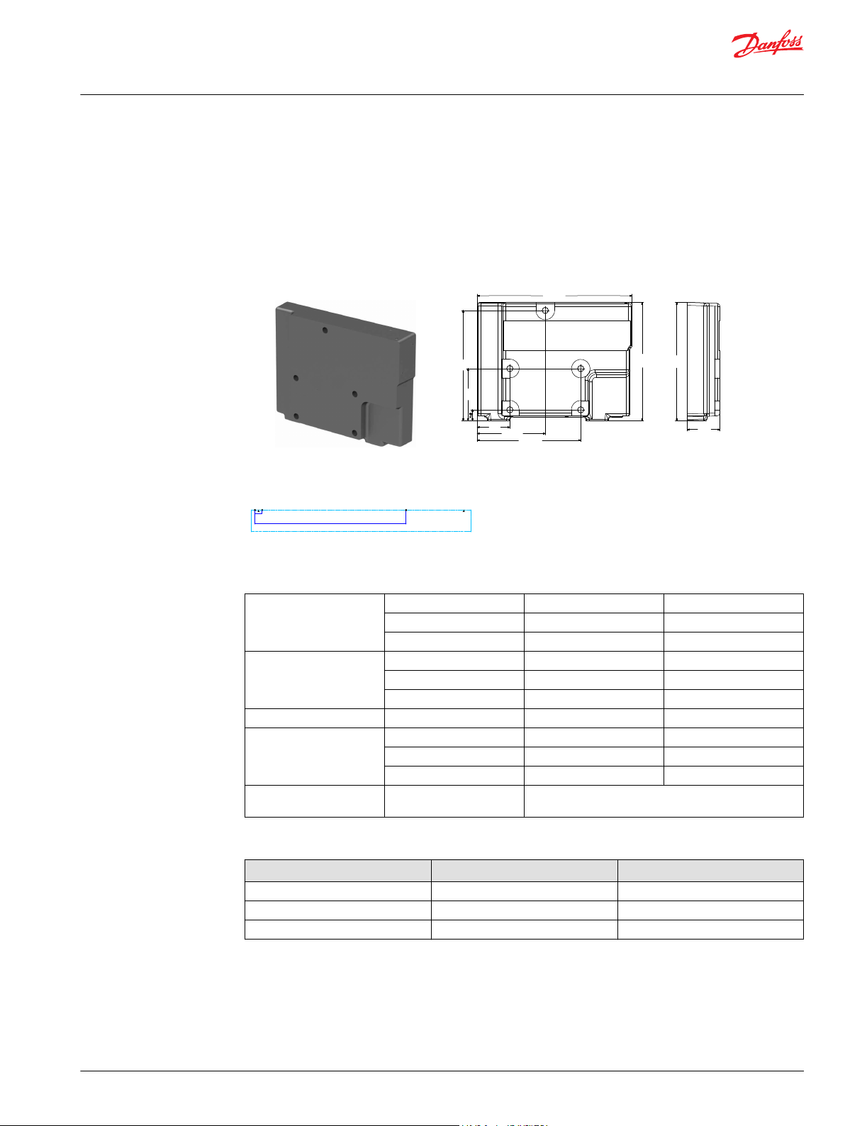
138.9
91.4
44
14.8
70
148
207.7
159
159
44
Weight: 7 kg [15.4 lb]
PVSI with or without LX connection
Dimensions
P109227
Technical Information
PVG 128/256 Technical Information
PVSI/PVGI End and Interface Plates
PVSI with or without LX-connection
The PVSI made of Cast Iron work as an End Plate.
The PVSI with LX connection enables another valves LS pressure to be shuttled to the pump when
needed.
The LX port treads are with BSP or UNF tread.
Schematic
Technical data
Max. rated pressure P-port continuous 350 bar [5076 psi]
P-port intermittent 400 bar [5800 psi]
T-port static/dynamic 25/40 bar [363/580 psi]
Oil temperature Recommended 30 to 60°C [86 to 140°F]
Minimum -30°C [-22°F]
Maximum 90° [194°F]
Ambient temperature Recommended -30 to 60°C [-22 to 140°F]
Oil viscosity Operating range 12 to 75 mm2/s [65 → 347 SUS]
Minimum 4 mm2/s [39 SUS]
Maximum 460 mm2/s 23/19/16
Oil contamination
according to ISO 4406
Maximum 23/19/16
Part numbers for PVSI End Plate with or without LX connection
Part number LX-port Mounting feet
11171419 - M12
11179950 G1/4"BSP M12
11179949 7/16-20 UNF M12
©
Danfoss | July 2021 BC220686485279en-000510 | 83
Page 84

167.9
138.9
89.9
43.9
91.4
159
148
116
70
66
14.8
36.5
Weight: 7 kg [15.4 lb]
PVSI with P and T port connections
Dimensions
P109205
Technical Information
PVG 128/256 Technical Information
PVSI/PVGI End and Interface Plates
PVSI with P and T port connections
The PVSI with P and T port connections enables an additional 600 l/min pump flow to a PVG 128/256
valve.
Metric and SAE flange connections as well as BSP and UNF treaded ports.
Schematic
Technical data
Max. rated pressure P-port continuous 350 bar [5076 psi]
P-port intermittent 400 bar [5800 psi]
T-port static/dynamic 25/40 bar [363/580 psi]
Oil temperature Recommended 30 to 60°C [86 to 140°F]
Minimum -30°C [-22°F]
Maximum 90° [194°F]
Ambient temperature Recommended -30 to 60°C [-22 to 140°F]
Oil viscosity Operating range 12 to 75 mm2/s [65 → 347 SUS]
Minimum 4 mm2/s [39 SUS]
Maximum 460 mm2/s 23/19/16
Oil contamination
according to ISO 4406
Part number P-port T-port Width Mounting
11171418 Metric Flange 1” Metric Flange 1-1/4” 37 mm M12
11179952 Thread Ports G1" BSP Thread Ports G1-1/4" BSP 44 mm M12
11171421 SAE Flange 1” UNF SAE Flange 1-1/4” UNF 37 mm M12
11171416 Thread Ports 1-5/16 UNF Thread Ports 1-5/8 UNF 44 mm M12
Maximum 23/19/16
feet
84 | © Danfoss | July 2021 BC220686485279en-000510
Page 85

138.9
91.4
44
14.8
70
148
207.7
159 159
36.5
Weight: 7 kg [15.4 lbs]
Dimensions
PVGI Interface plate
P109184
Technical Information
PVG 128/256 Technical Information
PVSI/PVGI End and Interface Plates
PVGI Interface Plate
The PVGI Interface Plate connects the P-, T-, LS- and Pp-channels in PVB 128/256 to the corresponding
channels in PVB 32 and/or 16 modules. T0 variant featured for PVB 32 modules equipped with T0.
Schematic
Technical data
Max. rated pressure P-port continuous 350 bar [5076 psi]
P-port intermittent 400 bar [5800 psi]
T-port static/dynamic 25/40 bar [363/580 psi]
Oil temperature Recommended 30 to 60°C [86 to 140°F]
Minimum -30°C [-22°F]
Maximum 90° [194°F]
Ambient temperature Recommended -30 to 60°C [-22 to 140°F]
Oil viscosity Operating range 12 to 75 mm2/s [65 → 347 SUS]
Minimum 4 mm2/s [39 SUS]
Maximum 460 mm2/s 23/19/16
Oil contamination
according to ISO 4406
Part number T0 PVGI width Mounting feet
11171422 No 37 mm M12
11171423 Yes 37 mm M12
Maximum 23/19/16
©
Danfoss | July 2021 BC220686485279en-000510 | 85
Page 86

Technical Information
PVG 128/256 Technical Information
PVAS
Stay Bolts for PVG 128 and 256 consists of 2 different kits:
1. PVAS containing 2 stay bolts – shall be placed in spec sheet under PVAS 1.
2. PVAS containing 3 stay bolts – shall be placed in spec sheet under PVAS 2.
Furthermore, O-rings is a part of the PVAS kits.
The table below shows which 2 PVAS kits required for the specification according to number of PVB 128
and/or PVB 256.
Table 1
0 1 2 3 4 5 6 7
PVB 128
0
1
2
3
4
5
6
7
8
9
11187320+
11188216
11187617+
11188213
11187655+
157B8023
11187684+
157B8005
11187658+
11188205
11187693+
11188202
11187705+
157B8009
11187692+
157B8030
11187710+
11188194
11187672+
11188215
11187677+
157B8022
11187678+
157B8004
11187679+
11188207
11187680+
11188204
11187699+
157B8008
11187703+
157B8029
11187694+
11188196
11187709+
11188189
11187673+
157B8003
11187681+
157B8024
11187682+
11188206
11187683+
11188203
11187696+
157B8028
11187688+
157B8010
11187704+
11188195
PVB 256
11187656+
11188208
11187658+
11188205
11187686+
157B8027
11187705+
157B8009
11187697+
11188197
11187710+
11188194
11187675+
157B8026
11187685+
157B8008
11187691+
11188199
11187694+
11188196
11187689+
157B8062
11187696+
157B8028
11187687+
11188198
11187704+
11188195
11187695+
157B8082
11187697+
11188197
11187690+
157B8081
11187689+
157B8062
Ex. For 2 PVB 256 and 1 PVB 128:
PVAS 1 = 11187681
PVAS 2 = 157B8024
For PVG 128/256 in combination with PVG 16/32 please see PVAS for Combo.
86 | © Danfoss | July 2021 BC220686485279en-000510
Page 87

Technical Information
PVG 128/256 Technical Information
PVAS
PVAS for Combo
Stay Bolts for PVG 128/256/16/32 consists of 2 different kits:
1. PVAS containing 2 stay bolts - please look in Table 2 and use P/N before + symbol.
2. PVAS containing 3 stay bolts – please look in Table 2 and write down the length in millimeters after
the + symbol.
Furthermore, O-rings is a part of the PVAS kits – no additional P/N needed.
Table 2.
0 1 2 3 4 5 6 7
PVB 128
0 11187676+
1
2
3
4
5
6
7
8
9
40
11187320+
106
11187617+
172
11187655+
238
11187684+
304
11187658+
370
11187693+
436
11187705+
502
11187692+
568
11187710+
634
11187672+
126
11187677+
192
11187678+
258
11187679+
324
11187680+
390
11187699+
456
11187703+
522
11187694+
588
11187709+
654
11187673+
212
11187681+
278
11187682+
344
11187683+
410
11187696+
476
11187688+
542
11187704+
608
PVB 256
11187656+
298
11187658+
364
11187686+
430
11187705+
496
11187697+
562
11187710+
628
11187675+
384
11187685+
450
11187691+
516
11187694+
582
11187689+
648
11187696+
470
11187687+
536
11187704+
602
11187695+
668
11187697+
556
11187690+
622
11187698+
642
Table 3.
PVB 16
0 1 2 3 4 5 6 7 8 9 10
0 64 104 144 184 224 264 304 344 384 424
1 72 112 152 192 232 272 312 352 392 432
2 120 160 200 240 280 320 360 400 440
3 168 208 248 288 328 368 408 448
4 216 256 296 336 376 416 456
PVB 32
5 264 304 344 384 424 464
6 312 352 392 432 472
7 360 400 440 480
8 408 448 488
9 456 496
10 504
Example
For 2 PVB 256 and 1 PVB 128 and 1 PVB 32 and 2 PVB 16:
PVAS 1 P/N = 11187681 from Table 2.
©
Danfoss | July 2021 BC220686485279en-000510 | 87
Page 88

Technical Information
PVG 128/256 Technical Information
PVAS
PVAS 2 = 278 mm from Table 2 + 152 mm from Table 3 = 278+152 =430 mm which equals 157B8027 in
Table 4.
PVAS Part Number Overview
Table 4.
Part number Accumulated module length in mm
157B8082 661-672
11188189 649-660
157B8062 637-648
11188194 625-636
157B8081 613-624
11188195 601-612
157B8061 589-600
11188196 577-588
157B8030 565-576
11188197 553-564
157B8010 541-552
11188198 529-540
157B8029 517-528
11188199 505-516
157B8009 493-504
11188200 481-492
157B8028 469-480
11188201 457-468
157B8008 445-456
11188202 433-444
157B8027 421-432
11188203 409-420
157B8007 397-408
11188204 385-396
157B8026 373-384
11188205 361-372
157B8006 349-360
11188206 337-348
157B8025 325-336
11188207 313-324
157B8005 301-312
11188208 289-300
157B8024 277-288
11188209 265-276
157B8004 253-264
11188210 241-252
157B8023 229-240
11188211 217-228
157B8003 205-216
11188212 193-204
88 | © Danfoss | July 2021 BC220686485279en-000510
Page 89

Technical Information
PVG 128/256 Technical Information
PVAS
Table 4. (continued)
Part number Accumulated module length in mm
157B8022 181-192
11188213 169-180
157B8002 157-168
11188214 145-156
157B8021 133-144
11188215 121-132
157B8001 109-120
11188216 97-108
157B8031 85-96
11188217 73-84
157B8000 61-72
11188218 49-60
11188219 20-48
©
Danfoss | July 2021 BC220686485279en-000510 | 89
Page 90

P109254
Technical Information
PVG 128/256 Technical Information
PVG Valve Schematics
Valve Schematics
PVG 128/256 Schematic with Basic End Plate
90 | © Danfoss | July 2021 BC220686485279en-000510
Page 91

P109255
Technical Information
PVG 128/256 Technical Information
PVG Valve Schematics
PVG 128/256 with P- and T-connection end plate
©
Danfoss | July 2021 BC220686485279en-000510 | 91
Page 92

349.9 [13.76]
579.1 [22.80]
111.3 [4.38]
47.5 [1.87]
100.5 [3.96]
78.5 [3.10]
131 [5.16]
68 [2.68]
43.5 [1.71]
189.4 [7.46]
P109644
349.9 [13.76]
567.4 [22.34]
99.6 [3.92]
47.5 [1.87]
100.5 [3.96]
78.5 [3.10]
131 [5.16]
68 [2.68]
189.4 [7.46]
43.5 [1.71]
P109645
Technical Information
PVG 128/256 Technical Information
Dimension Overview
Dimension Overview for PVG 128/256
PVEO
PVEH
92 | © Danfoss | July 2021 BC220686485279en-000510
Page 93
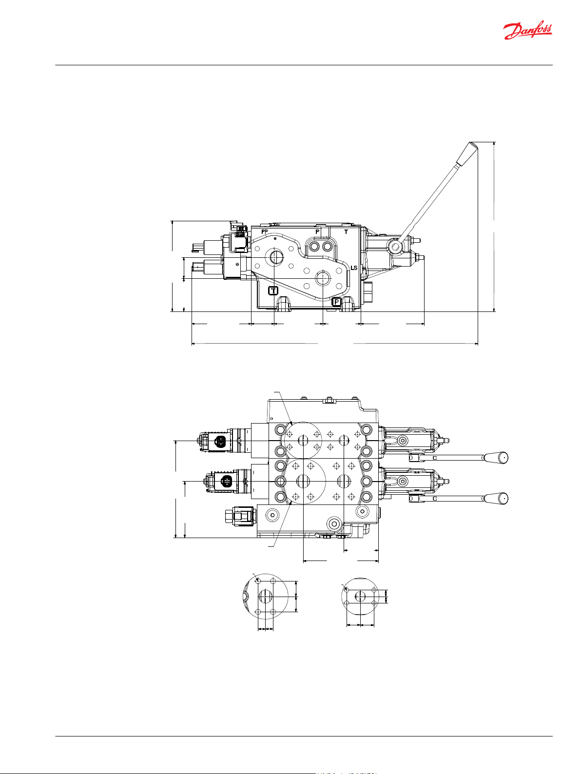
349.9 [13.76]
590.5 [23.25]
122.7 [4.83]
47.5 [1.87]
100.5 [3.96]
78.5 [3.10]
131 [5.16]
68 [2.68]
43.5 [1.71]
187.2 [7.37]
P109646
B
181 [7.13]
105 [4.13]
A
A
B
140.5 [5.53]
64.5 [2.54]
119 [0.47]
25.4
[1.00]
28.6 [1.13]
13.9
[0.55]
8xM12-6H
8xM10-6H
P109647
Technical Information
PVG 128/256 Technical Information
Dimension Overview
PVHC
PVG 128/256 Dimensions
©
Danfoss | July 2021 BC220686485279en-000510 | 93
Page 94

Technical Information
PVG 128/256 Technical Information
Dimension Overview
Number of PVB 256 Number of PVB 128
0 1 2 3 4 5 6 7 8 9
0 L1 mm - 98.5 164.5 230.5 296.5 362.5 428.5 494.5 560.5 626.5
[in] - [3.88] [6.48] [9.07] [11.67] [14.27] [16.87] [19.47] [22,07] [24.67]
L2 mm - 176.5 249.5 309.5 382.5 443.5 515.5 576.5 649.5 709.5
[in] - [6.95] [9.82] [12.19] [15.06] [17.46] [20.30] [22.70] [25.57] [27.93]
1 L1 mm 118.5 184.5 250.5 316.5 382.5 448.5 514.5 580.5 646.5 -
[in] [4.67] [7.26] [9.86] [12.46] [15.06] [17.66] [20.26] [22.85] [25.45] -
L2 mm 200.5 273.5 334.5 406.5 467.5 540.5 600.5 673.5 734.5 -
[in] [7.89] [10.77] [13.17] [16.00] [18.41] [21.28] [26.64] [26.52] [28.92] -
2 L1 mm 204.5 270.5 336.5 402.5 468.5 534.5 600.5 - - -
[in] [8.05] [10.65] [13.25] [15.85] [18.44] [21.04] [23.64] - - -
L2 mm 285.5 358.5 418.5 491.5 552.5 625.5 685.5 - - -
[in] [11.24] [14.11] [16.48] [19.35] [21.75] [24.63] [26.99] - - -
3 L1 mm 290.5 356.5 422.5 488.5 554.5 520.5 - - - -
[in] [11.44] [14.04] [16.63] [19.23] [21.83] [24.43] - - - -
L2 mm 370.5 443.5 503.5 576.5 637.5 709.5 - - - -
[in] [14.59] [17.46] [19.82] [22.70] [25.10] [27.93] - - - -
4 L1 mm 376.5 442.5 508.5 574.5 640.5 - - - - -
[in] [14.82] [17.42] [20.02] [22.62] [25.22] - - - - -
L2 mm 467.5 528.5 600,5 661.5 734.5 - - - - -
[in] [18.40] [20.81] [23.64] [26.04] [28.92] - - - - -
5 L1 mm 462.5 528.5 594.5 660.5 - - - - - -
[in] [18.21] [20.81] [23.41] [26.00] - - - - - -
L2 mm 552.5 612.5 685.5 746.5 - - - - - -
[in] [21.75] [24.11] [26.99] [29.39] - - - - - -
6 L1 mm 548.5 614.5 - - - - - - - -
[in] [21.59] [24.19] - - - - - - - -
L2 mm 637.5 697.5 - - - - - - - -
[in] [25.10] [27.46] - - - - - - - -
7 L1 mm 634.5 - - - - - - - - -
[in] [24.98] - - - - - - - - -
L2 mm 722.5 - - - - - - - - -
[in] [28.44] - - - - - - - - -
94 | © Danfoss | July 2021 BC220686485279en-000510
Page 95

Technical Information
PVG 128/256 Technical Information
Dimension Overview
Specifications example
©
Danfoss | July 2021 BC220686485279en-000510 | 95
Page 96

Danfoss
Power Solutions GmbH & Co. OHG
Krokamp 35
D-24539 Neumünster, Germany
Phone: +49 4321 871 0
Danfoss
Power Solutions ApS
Nordborgvej 81
DK-6430 Nordborg, Denmark
Phone: +45 7488 2222
Danfoss
Power Solutions (US) Company
2800 East 13th Street
Ames, IA 50010, USA
Phone: +1 515 239 6000
Danfoss
Power Solutions Trading
(Shanghai) Co., Ltd.
Building #22, No. 1000 Jin Hai Rd
Jin Qiao, Pudong New District
Shanghai, China 201206
Phone: +86 21 2080 6201
Products we offer:
Hydro-Gear
www.hydro-gear.com
Daikin-Sauer-Danfoss
www.daikin-sauer-danfoss.com
Cartridge valves
•
DCV directional control
•
valves
Electric converters
•
Electric machines
•
Electric motors
•
Gear motors
•
Gear pumps
•
Hydraulic integrated
•
circuits (HICs)
Hydrostatic motors
•
Hydrostatic pumps
•
Orbital motors
•
PLUS+1® controllers
•
PLUS+1® displays
•
PLUS+1® joysticks and
•
pedals
PLUS+1® operator
•
interfaces
PLUS+1® sensors
•
PLUS+1® software
•
PLUS+1® software services,
•
support and training
Position controls and
•
sensors
PVG proportional valves
•
Steering components and
•
systems
Telematics
•
Danfoss Power Solutions is a global manufacturer and supplier of high-quality hydraulic and
electric components. We specialize in providing state-of-the-art technology and solutions
that excel in the harsh operating conditions of the mobile off-highway market as well as the
marine sector. Building on our extensive applications expertise, we work closely with you to
ensure exceptional performance for a broad range of applications. We help you and other
customers around the world speed up system development, reduce costs and bring vehicles
and vessels to market faster.
Danfoss Power Solutions – your strongest partner in mobile hydraulics and mobile
electrification.
Go to www.danfoss.com for further product information.
We offer you expert worldwide support for ensuring the best possible solutions for
outstanding performance. And with an extensive network of Global Service Partners, we also
provide you with comprehensive global service for all of our components.
Local address:
Danfoss can accept no responsibility for possible errors in catalogues, brochures and other printed material. Danfoss reserves the right to alter its products without notice. This also applies to products
already on order provided that such alterations can be made without subsequent changes being necessary in specifications already agreed.
All trademarks in this material are property of the respective companies. Danfoss and the Danfoss logotype are trademarks of Danfoss A/S. All rights reserved.
©
Danfoss | July 2021 BC220686485279en-000510
 Loading...