

MAKING MODERN LIVING POSSIBLE
Service and Parts Manual
Proportional Valves
PVG 100
powersolutions.danfoss.com

Service and Parts Manual PVG 100 Proportional Valves
Contents
Function
Installation
Service parts
PVG 100 sectional drawing .............................................................................................................................................3
Installation and plug orientation ..................................................................................................................................4
Installation and identication ........................................................................................................................................5
Maximum ow setting .................................................................................................................................................6-7
Connections .........................................................................................................................................................................8
Tightening torques ............................................................................................................................................................8
Installation of lever ............................................................................................................................................................9
Pressure setting, PVP .........................................................................................................................................................9
Adjustment of PVE .......................................................................................................................................................... 10
Installation and technical data for PVPP ................................................................................................................. 11
Pilot drain connection ................................................................................................................................................... 11
PVMR disassembly .......................................................................................................................................................... 12
PVMR/F assembly ............................................................................................................................................................ 13
Tightening torques and widths across ats ........................................................................................................... 13
Main spool assembly for PVMR .................................................................................................................................. 14
Float spool assembly for PVMF................................................................................................................................... 15
PVPF, open center pump side module ..............................................................................................................16-17
PVPE, PVPD and Pilot Shut O .............................................................................................................................. 18-19
PVPV - closed center pump side module ..........................................................................................................20-21
PVPV - closed center pump side module with integrated priority function ........................................22-23
PVB, PVBZ, PVLA, and PVLP ....................................................................................................................................24-25
PVSI, PVT, and PVTI ...................................................................................................................................................26-27
PVAS assembly kit for PVP with PVSI/PVT .........................................................................................................28-29
PVAS assembly kit for PVP with PVTI ..................................................................................................................30-31
PVBS, main spool ....................................................................................................................................................... 32-33
PVM, mechanical activation .................................................................................................................................. 34-35
PVM, PVMD, PVH, PVMR, and PVMF cover ........................................................................................................36-37
Electrical activation with Hirschmann connector ......................................................................................... 38-39
Electrical activation with AMP connector ........................................................................................................ 40-41
Seal kits for PVG 100 ....................................................................................................................................................... 42
2
520L0888 • Rev BB • Feb 2015
Service and Parts Manual PVG 100 Proportional Valves
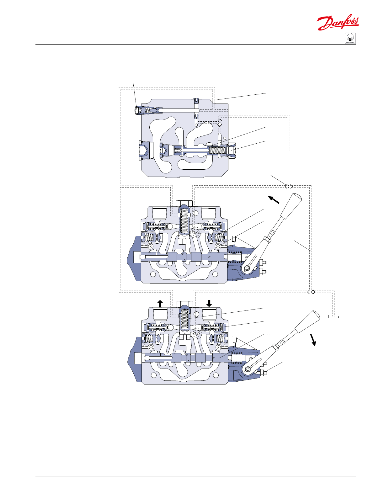
Function
PVG 100
sectional drawing
1
T
port
CF
P
T
LS
comp.
13
LS
pump
P
port
LS
ST
2
3
4
5
A
BA
6
8
7
P
T
BA
P
T
1. LS relief valve
2. LS connection
3. Priority spool for CF
4. LS connection for steering unit
5. Shuttle valve
6. Pilot operated check valve, POC
7. LS line
T
9
10
11
B
12
T
P106 002E
8. Logic cartridge for POC
9. Pressure compensator
10. Shock and suction valve, PVLP
11. Main spool, PVBS
12. Max. oil flow adjustment screws for ports A and B
13. LS comp (LS signal sent back to compensators)
520L0888 • Rev BB • Feb 2015
3
Service and Parts Manual PVG 100 Proportional Valves
L
[530 lbf•in]
]
orientation
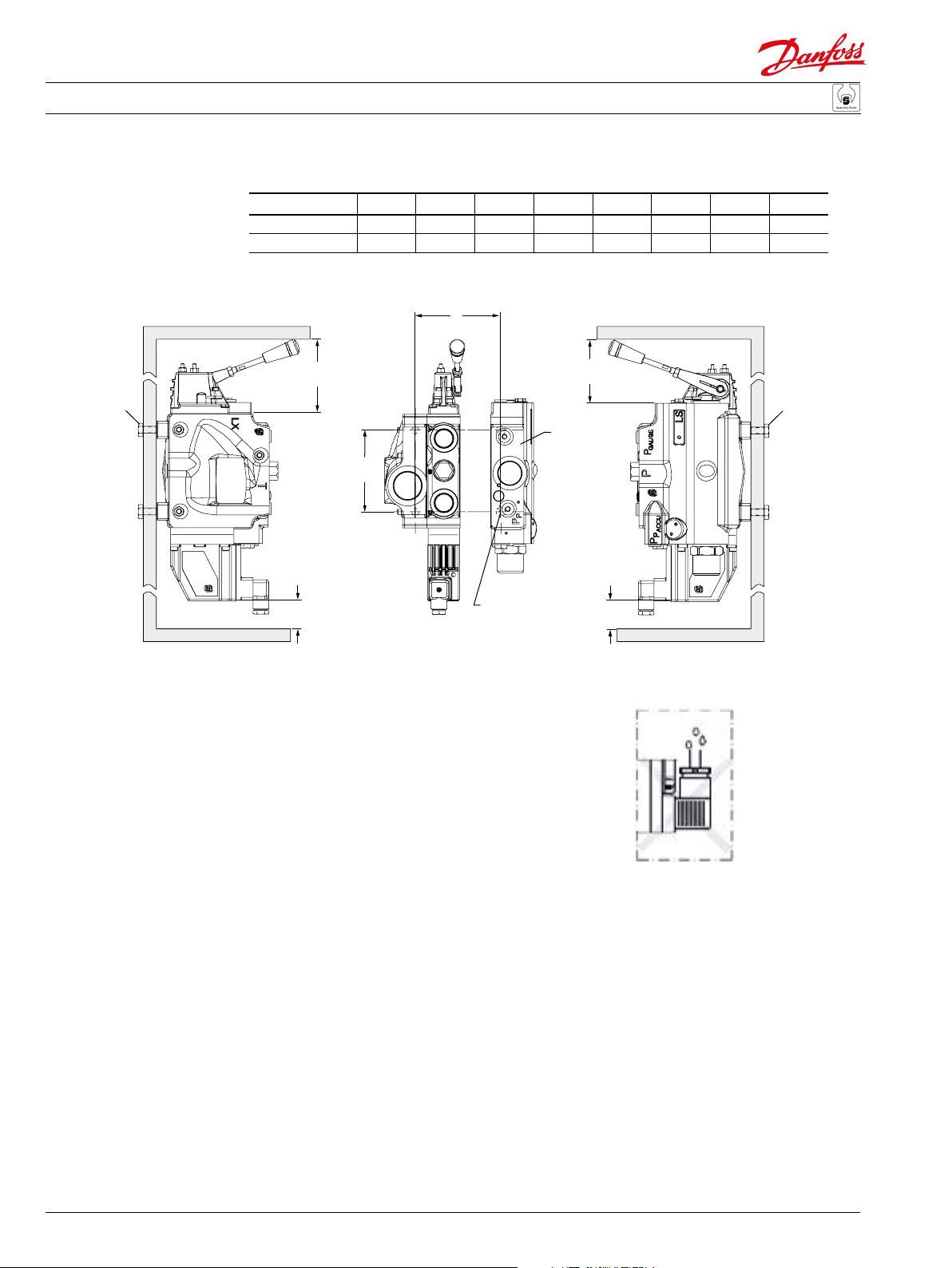
Installation
Installation and plug
orientation
60 Nm
Module of PVB 1 2 3 4 5 6 7 8
L mm 80.0 128.0 176.0 224.0 272.0 320.0 368.0 416.0
L in 3.15 5.04 6.93 8.82 10.71 12.60 14.49 16.38
PVP
170*
[6.69]
60 Nm
[530 lbf•in
170*
[6.69]
118
[4.65]
A
T
P
B
100*
[4]
* Room for dismantling
M12 x 14.0
4 places
100*
[4]
P106 000E
DIN mounting
4
520L0888 • Rev BB • Feb 2015

Service and Parts Manual PVG 100 Proportional Valves
E101 279E
PVEH/
C:
D:
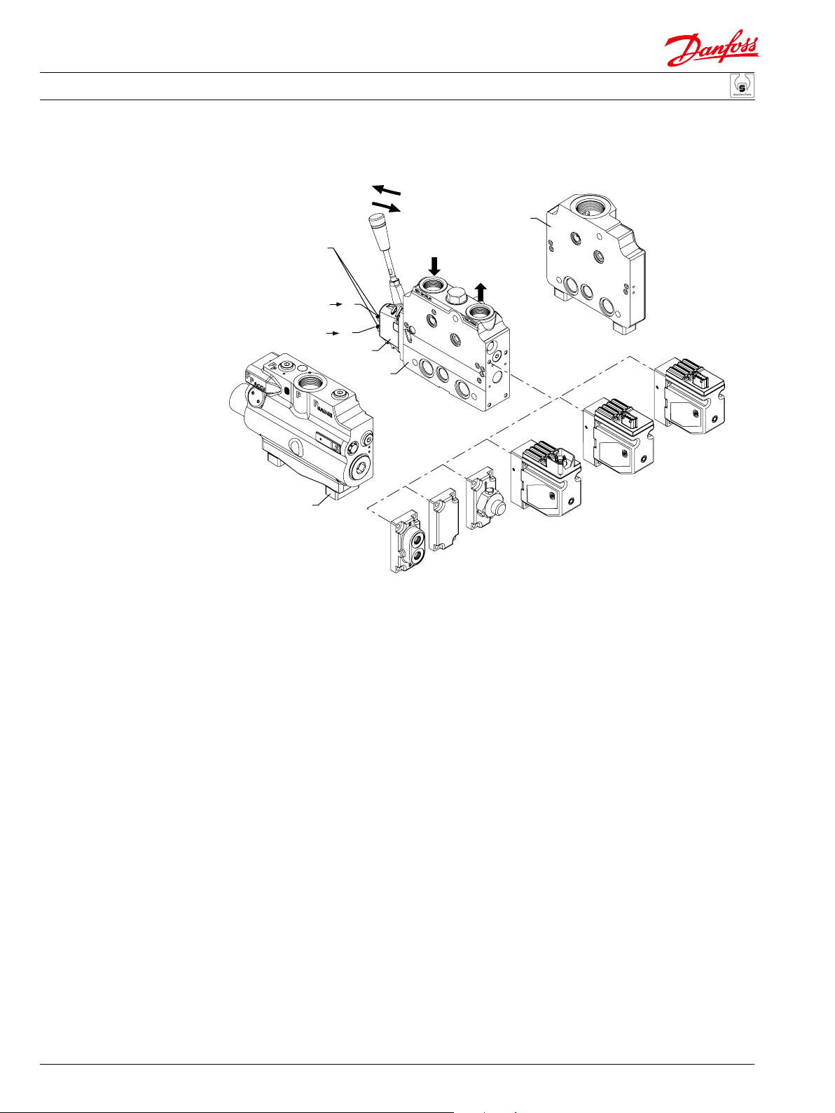
Installation and Identication
Standard, oil ow direction
and setting of max ow
PVM to the right of PVP
Identication
PVMR/
PVMF
PVMD
PVH
PVEO
PVEA
PVB
PVES
B
A
PVM
7-9 Nm
[61-79 lbf•in]
P-A
PVS
P-B
Q max: P B
Q max: P A
PVP
Q max. A
Q max. B
01 03 A 00 0299
Week of manufacture
Year of manufacture
Day of the week
(A = Monday, B = Tuesday ...)
Issue number
Series number
PVG code number, week and year of manufacture
PVP pressure setting
C
D
Q max. B
Q max. A
3 mm
+
Q max. A
+
Q max. B
8 Nm
[70 lbf•in]
10 mm
520L0888 • Rev BB • Feb 2015
5
Service and Parts Manual PVG 100 Proportional Valves
Installation
Option, oil ow direction
and setting of max ow
PVM to the left of PVP
7-9 Nm
[61-79 lbf•in]
Q max: P A
Q max: P B
PVP
P-A
PVM
PVB
P-B
PVH
B
PVMD
A
PVMR/
PVMF
PVS
PVEO
PVEA
PVEH/
PVES
E101 284E
6
520L0888 • Rev BB • Feb 2015

Service and Parts Manual PVG 100 Proportional Valves
Installation
Connections, pump side
module, PVP
end plate, PVS
Tightening torque
T
B
A
Pp gauge
(PVP-OC)
PAccu
PVP-OC shown
T0
P
Pp gauge
LS
LX
E101 285E
Maximum tightening torque
Connection
G 3/4 G 1 G 3/4 G 1/4 G 1 G 1 1/4
BSPP port connection
210 Nm 330 Nm 210 Nm 40 Nm 330 Nm 540 Nm
With steel washer
1850 lbf·in 2920 lbf·in 1850 lbf·in 350 lbf·in 2920 lbf·in 4780 lbf·in
50 Nm 70 Nm 50 Nm 20 Nm 70 Nm 100 Nm
With copper washer
445 lbf·in 620 lbf·in 445 lbf·in 180 lbf·in 620 lbf·in 885 lbf·in
110 Nm 150 Nm 110 Nm 30 Nm 150 Nm 240 Nm
With aluminum washer
970 lbf·in 1330 lbf·in 970 lbf·in 270 lbf·in 1330 lbf·in 2125 lbf·in
210 Nm 330 Nm 210 Nm 40 Nm 330 Nm 540 Nm
With cutting edge
1850 lbf·in 2920 lbf·in 1850 lbf·in 350 lbf·in 2920 lbf·in 4780 lbf·in
1 1/16 in-12 1 5/16 in-12 1 1/16 in-12 9/16 in-18 1 5/16 in-12 1 5/8 in-12
UNF port connection
120 Nm 160 Nm 120 Nm 40 Nm 160 Nm 320 Nm
With O-ring
1040 lbf·in 1420 lbf·in 1040 lbf·in 350 lbf·in 1420 lbf·in 2830 lbf·in
LS, LX, T0
P A/B Gauge: P, Pp, T
P
p Accum.
520L0888 • Rev BB • Feb 2015
7

Service and Parts Manual PVG 100 Proportional Valves
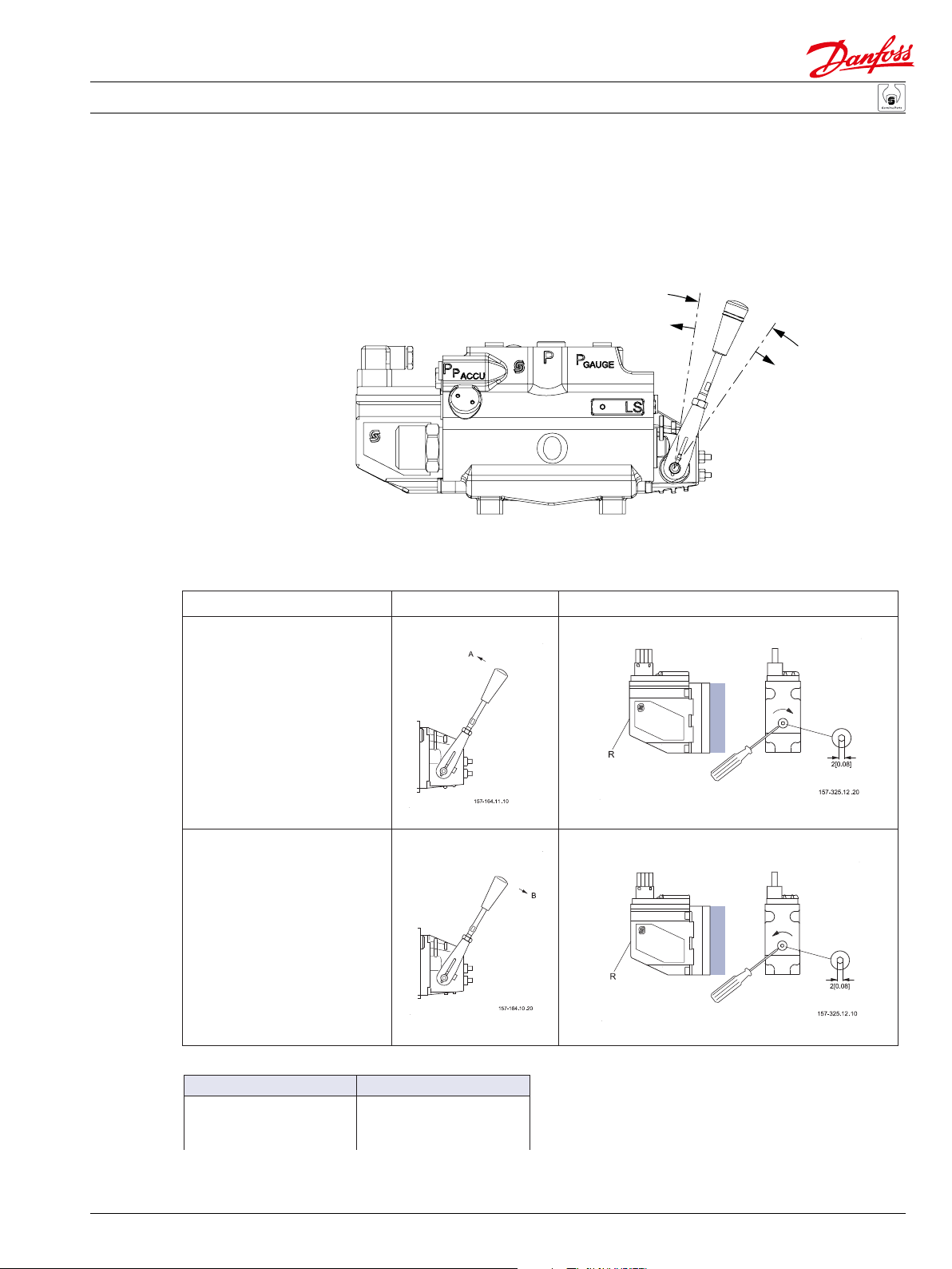
Installation
Installation of lever
Pressure setting, PVP
Base with an angle of 22.5° Base with an angle of 37.5°
P106 007E
PVP-CC
PVP-OC
4 mm
360° ~ 120 bar
360° ~ 1740 psi
P106 008E
8
520L0888 • Rev BB • Feb 2015
Service and Parts Manual PVG 100 Proportional Valves
0
.
0
8
]
Installation
PVEH/PVEM/PVES
Adjustment of PVE
when max. lever travel is
exceeded
(PVE is factory-preset)
Lever travel exceeded in
Check maximum lever travel in neutral position.
1. Make sure the system is supplied with hydraulic power.
2. Connect supply voltage (UDC) (Signal voltage 0.5 x UDC), or cut o the signal voltage (US) on
pin 2.
[
2
.
x
a
m
A
m
a
x
.
2
B
[
0
.
0
8
]
PVG 100
Direction of rotation for adjustment of position transducer
Direction A
Direction B
Turn of transducer Movement of lever
1
/4
1
/2
3
/4
1.5 mm [0.06 in]
3.0 mm [0.12 in]
4.5 mm [0.18 in]
520L0888 • Rev BB • Feb 2015
9
Service and Parts Manual PVG 100 Proportional Valves
][
][
A0
A0
W1
W1
e±
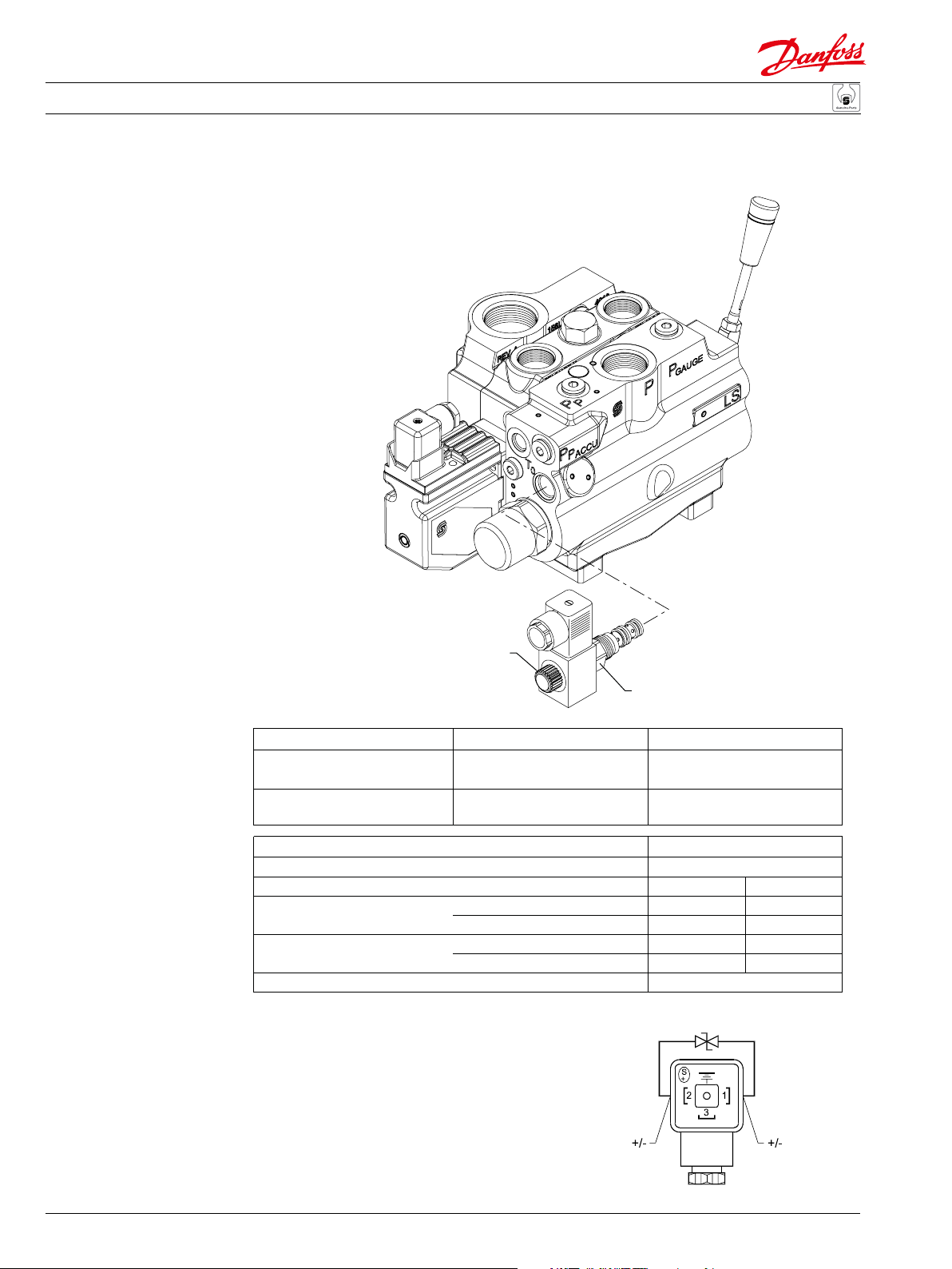
Installation
Installation and technical
data for pvpp (solenoid
operated pilot drain)
PVPP connection
2
(coil nut)
1
(cartridge valve)
Position Max. tightening torque
1
2
Max. operation pressure 350 bar [5076 bar]
Max. coil surface temperature 155°C [311°F]
Rated voltage 12 V
Current consumtion
Power consumtion
Max. permissible deviation from rated supply voltag
When installing the wire remember to
connect the built-in diode to the plug
22°C (71,6°F) coil temperature1.55
110°C (230°F) coil temperature1.00
22°C (71,6°F) coil temperature19
110°C (230°F) coil temperature12
Across flats
24 mm 45 Nm
[0.94 in
20 mm 5 Nm
[0.79 in
__
––
400 lbf·in]
44 lbf·in]
10%
pins.
24 V
.78 A
.50 A
9 W
2 W
__
––
P106 004E
10
520L0888 • Rev BB • Feb 2015
Service and Parts Manual PVG 100 Proportional Valves
][
][
W1
W1
e±
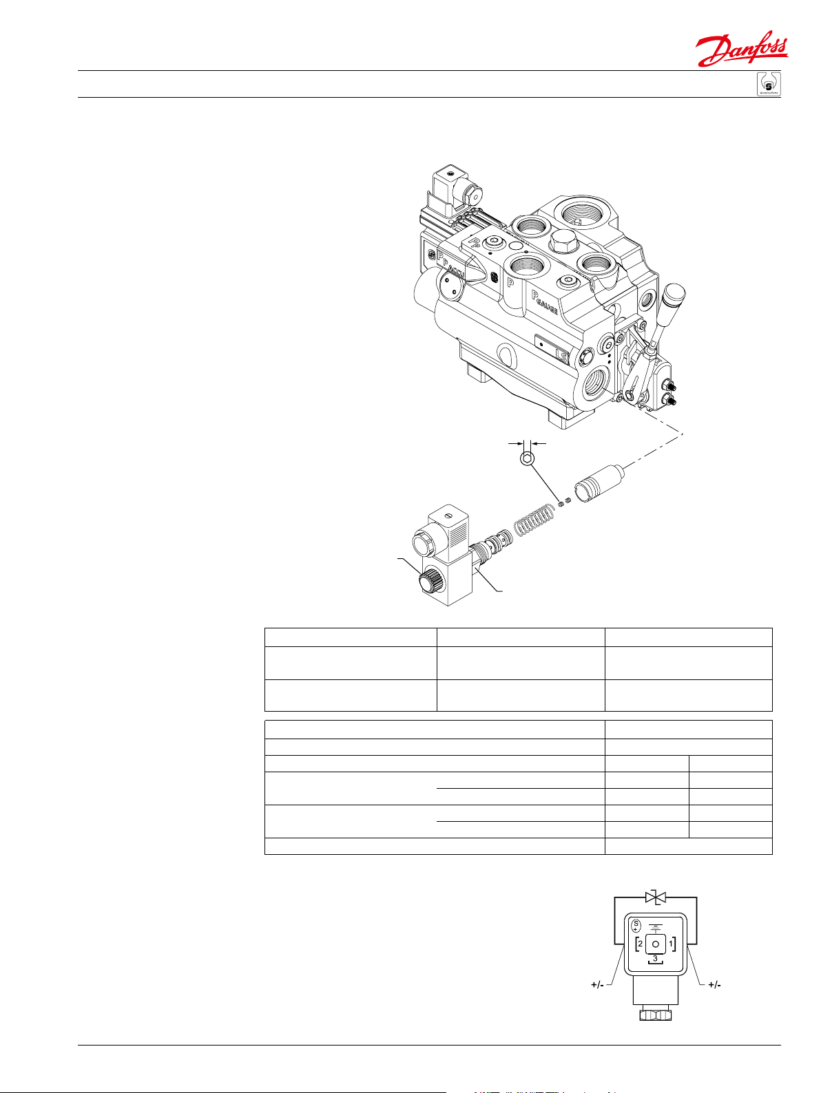
Installation
Installation and technical
data for PVPE (solenoid
relief valve)
2 Nm
[17.5 lbf•in]
2.5 mm
PVPE connection
1
(coil nut)
2
(cartridge valve)
Position Max. tightening torque
Max. operation pressure 350 bar [5076 bar]
Max. coil surface temperature 155°C [311°F]
Rated voltage 12 V
Current consumtion
Power consumtion
Max. permissible deviation from rated supply voltag
When installing the wire remember to
connect the built-in diode to the plug
1
2
22°C (71,6°F) coil temperature1.55 A0.78 A
110°C (230°F) coil temperature1.00 A0.50 A
22°C (71,6°F) coil temperature19
110°C (230°F) coil temperature12
Across flats
22 mm 5 Nm
[0.87 in
36 mm 85 Nm
[1.42 in
__
––
45 lbf·in]
750 lbf·in]
10%
pins.
24 V
9 W
2 W
__
––
520L0888 • Rev BB • Feb 2015
P106 288E
11
Service and Parts Manual PVG 100 Proportional Valves
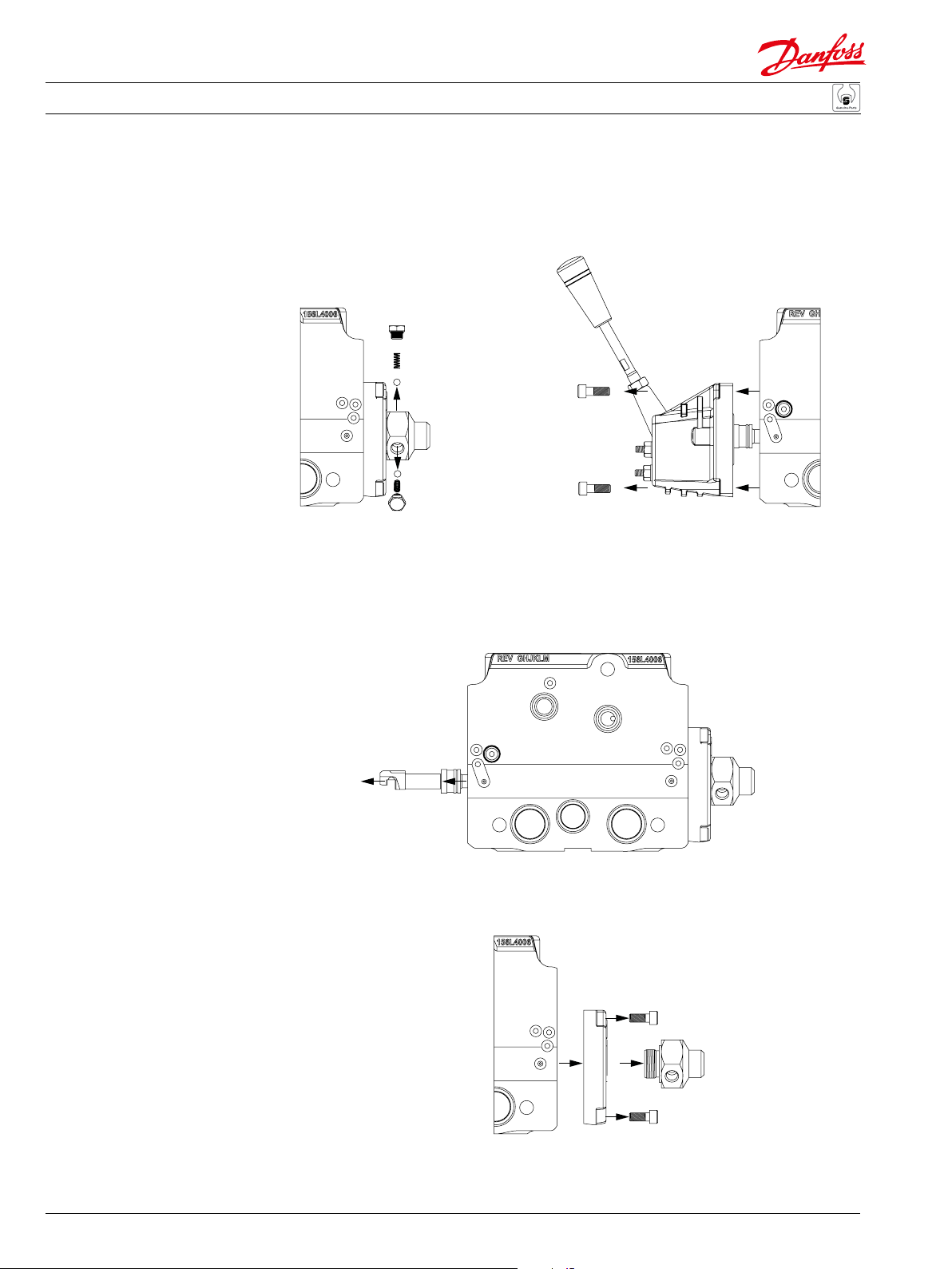
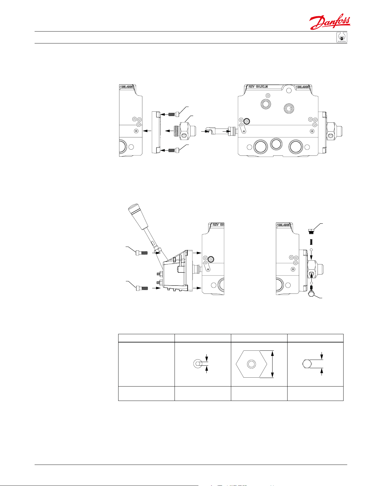
Installation
PVMR disassembly
1. 2.
3.
4.
P106 005
12
520L0888 • Rev BB • Feb 2015
Service and Parts Manual PVG 100 Proportional Valves
2.
Installation
PVMR/F assembly
1.
X
Y
X
3. 4.
X
Z
Tightening torques and
widths across ats
X
Width across flats
Tightening torque
XYZ
5 mm
8 ± 0.5 Nm 15 ± 2 Nm 4 ± 1 Nm
[70 ± 4.5 lbf·in][135 ± 20 lbf·in][35 ± 9 lbf·in]
36 mm
Z
11 mm PVMF
P106 006
19 mm PVMR
520L0888 • Rev BB • Feb 2015
13
Service and Parts Manual PVG 100 Proportional Valves
1.
2.
Installation
Standard main spool
assembly for PVMR
11 mm
3.
12.5 mm
4.
8 Nm
[70 lbf·in]
12 mm
8 Nm
[70 lbf·in]
Note: Spools must be installed with LS holes
on ‘B’ port side of PVB.
14
520L0888 • Rev BB • Feb 2015
E101 291E

Service and Parts Manual PVG 100 Proportional Valves
Installation
Standard oat spool
assembly for PVMF
A F
P
Note: Spools must be installed with LS holes
on ‘B’ port side of PVB.
11 mm
12 mm
8 Nm
[70 lbf·in]
8 Nm
[70 lbf·in]
E101 290E
520L0888 • Rev BB • Feb 2015
15

Service and Parts Manual PVG 100 Proportional Valves
Service parts
PVPF, open center pump
side module
4 mm
18
[35 lbf•in]
19
4 mm
4 Nm
16
11
[177 lbf•in]
12
12
20 Nm
11
12
12
20
10
21
22
15
14
13
12
1
26
2.5 mm
11
12
17
2
3 Nm
[25 lbf•in]
6 mm
12
12
25
35 Nm
[310 lbf•in]
11
24
23
3
85 Nm
[750 lbf•in]
27
6 mm
4 Nm
[35 lbf•in]
4
41 mm
5
6
7
E101 303E
16
520L0888 • Rev BB • Feb 2015

Service and Parts Manual PVG 100 Proportional Valves
Service parts
Type Description Code number
G1 thread UNF thread
PVPF 161B5110
161B5510
161B5112
161B5512
PVPF 161B5140
161B5540
161B5142
161B5542
Item Description Code No.
1 Spool, 12 bar 1 1 1 1
1 Spool, 20 bar 1 1 1 1
2 Orifice, 0.7 dia, M5 1 1 1 1 1 1 1 1
3 Washer, 19.3 x 34.0 x 3.0 [0.76 x 1.34 x 0.12] 1 1 1 1 1 1 1 1
4 Spring, 12 bar 1 1 1 1
4 Spring, 20 bar 1 1 1 1
5 Spring, 12 bar 1 1 1 1
5 Spring, 20 bar 1 1 1 1
6 O-ring, 33.3 x 2.4 [1.31 x 0.09] 1 1 1 1 1 1 1 1
7 Plug 1 1 1 1 1 1 1 1
10 Orifice, 0.7 dia, M8 x 1 1 1 1 1 1 1 1 1
11 Plug, G 1/4 thread 631X2036 4 4 4 4
11 Plug, 9/16-18 UNF thread 4 4 4 4
12 O-ring, 11.9 x 1.98 [0.47 x 0.08] 4 4 4 4
12 Washer, 13.5 x 17.5 x 1.5 [0.53 x 0.69 x 0.06] 4 4 4 4
13 LS relief valve 155L6485 1 1 1 1 1 1 1 1
14 Plastic cap 155L6377 1 1 1 1 1 1 1 1
15 Plastic plug w/O-ring (1 5/16-12 UNF thread) 156H7047 1 1 1 1
15 Plastic plug w/gasket (G1 thread) 633X0176 1 1 1 1
16 Plug assembly, w/O-ring (9/16-18 UNF thread) 30021-6A 4 4 4 4
17 Plastic plug w/gasket (9/16-18 UNF thread) 156H7043 1 1 1 1
17 Plastic plug w/gasket (G 1/4 thread) 633X0123 1 1 1 1
18 Cap plug assembly w/O-ring 1 1 1 1 1 1 1 1
19 Spring, PR 1 1 1 1 1 1 1 1
20 Spool, PR 1 1 1 1 1 1 1 1
21 Filter retainer (non-serviceable) 1 1 1 1 1 1 1 1
22 Filter, PR (non-serviceable) 1 1 1 1 1 1 1 1
23 Screw, pilot check valve (M10 x 1) 1 1 1 1
24 Spring, pilot check valve 1 1 1 1
25 Ball, pilot check valve (M6 steel) 1 1 1 1
26 Orifice, 0.4 dia (M10 x 1) 1 1 1 1 1 1 1 1
27 Plug assembly, w/seal (M12 x 1.5) 1 1 1 1 1 1 1
Seal kit (includes item 6 and 12) 11016012 1 1 1 1 1 1 1 1
LS relief valve service tool 155L6494
Open center with pilot
supply for electrical
actuation and pilot gage
port
Open center with pilot
supply for electrical
actuation, pilot gage
port, and facility for
pilot shut o
12 bar
spring
20 bar
spring
12 bar
spring
20 bar
spring
1
520L0888 • Rev BB • Feb 2015
E101 304E
17

Service and Parts Manual PVG 100 Proportional Valves
Service parts
PVPE, PVPD and pilot
shut-o (PVPP)
85 Nm
[750 lbf•in]
17 mm
1
2
10
9
36 mm
85 Nm
[750 lbf•in]
2.5 mm
3
4
5
6
11
7
8
1
2 Nm
[17.5 lbf•in]
15
16
18
19
20
17
24 mm
13
13
5 Nm
[44.2 lbf•in]
12
14
35-40 Nm
[310-354 lbf•in]
E101 305E
18
520L0888 • Rev BB • Feb 2015

Service and Parts Manual PVG 100 Proportional Valves
Service parts
PVPE, PVPD and pilot
shut-o (PVPP)
Type Code No.
12 volt 155G5052
PVPE
24 volt 155G5054
PVPD Accessory plug (PVPF only) 155G5041
Electrical pilot shut-o valve 12 volt 161B5052
PVPP
(PVPV or PVPF) 24 volt 161B5054
Item Description Code No.
1 Electrical plug 155G5451 1 1 1 1
2 Electrical relief valve, 12 volt (item 3, 4, and 5 included) 155G5013 1
2 Electrical relief valve, 24 volt (item 3, 4, and 5 included) 155G5025 1
3 O-ring, 29.82 x 2.62 [1.18 x 0.10] 1 1
4 Back-up ring 27.0 x 2.0 [1.06 x 0.08] 1 1
5 O-ring, 26.7 x 1.78 [1.05 x 0.07] 1 1
6 Spring 1 1
7 Orifice, M5 x 0.5 dia. [ 0.2 x 0.02] 2 2
8 Spool 1 1
9 Plug (item 10 included) 1
10 O-ring, 30.3 x 2.4 [1.19 x 0.09] 1
11 Insert (item 9 and 10 included) 155G5041 1
12 Coil nut (item 13 included) 173800588 1 1
13 O-ring, 6-065 viton, 75D, 12 x 2 [0.47 x 0.08] 2 2
14 Coil, 12 volt, 22w DIN 171139819 1
14 Coil, 24 volt, 22w, DIN 171140019 1
15 Solenoid valve (item 12, 16, 17, 18, 19, and 20 included) 805339919 1 1
16 O-ring, 16.4 x 2.2 [0.65 x 0.09](3-908)D 1 1
17 Back-up ring, 8-014, 11.02 x 13.8 x 0.7 [0.43 x 0.54 x 0.03] 2 2
18 O-ring, 2-014 1 1
19 O-ring, 2-013 1 1
20 Back-up ring, 8-013 2 2
PVPE seal kit (includes item 3, 4, and 5) 155G8527 1 1
PVPP seal kit (includes item 10, 13, 16, 17, 18, 19, and 20) 35400321 1 1
Extra electrical relief
( PVPF only)
520L0888 • Rev BB • Feb 2015
E101 306E
19

Service and Parts Manual PVG 100 Proportional Valves
Service parts
PVPV, closed center pump
side module
35 ± 3 Nm
[310 ± 5 lbf•in]
23
6 mm
24
6 mm
16
25
Service tool
torque
20 Nm
[177 lbf•in]
17
16
35 ± 3 Nm
[310 ± 5 lbf•in]
14
13
15
11
12
6 mm
16
22
35 ± 3 Nm
[310 ± 5 lbf•in]
10
17
21
20
13 mm
85 Nm
[750 lbf•in]
19
18
20
E101 334E
520L0888 • Rev BB • Feb 2015

Service and Parts Manual PVG 100 Proportional Valves
Service parts
PVPV, closed center pump
side module
Type Description Code number
G1 thread UNF thread
161B5111
Closed center with pilot supply for
electrical actuation and pilot gage port
161B5511
11013069
PVPV 11013070
161B5141
161B5541
11013075
11013076
Item Description Code No.
10 Orifice, 0.7 dia, M8 x 1 1 1 1 1 1 1 1 1
11 Plug, G 1/4 thread 631X2037 3 3 2 2
11 Plug, 9/16-18 UNF thread 3 3 2 2
12 Washer, 13.5 x 17.5 x 1.5 [0.53 x 0.69 x 0.06] 3 3 2 2
12 O-ring, 11.9 x 1.98 [0.47 x 0.08] 3 3 2 2
13 LS relief valve 1 1 1 1 1 1 1 1
14 Plastic cap 155L6377 1 1 1 1 1 1 1 1
15 Plastic plug w/O-ring (1 5/16-12 UNF thread) 156H7047 1 1 1 1
15 Plastic plug w/gasket (G1 thread) 633X0176 1 1 1 1
16 Plug assembly, w/O-ring (9/16-18 UNF thread) 30021-6A 3 3 2 2
17 Plastic plug w/gasket (9/16-18 UNF thread) 156H7043 2 2 2 2
17 Plastic plug w/gasket (G 1/4 thread) 2 2 2 2
18 Cap plug assembly w/O-ring 156H7051 1 1 1 1 1 1 1 1
19 Spring, PVE 1 1 1 1
19 Spring, PVH 1 1 1 1
20 Spool, PR 1 1 1 1 1 1 1 1
21 Filter retainer (non-serviceable) 1 1 1 1 1 1 1 1
22 Filter, PR (non-serviceable) 1 1 1 1 1 1 1 1
23 Screw, pilot check valve (M10 x 1) 1 1 1 1 1 1 1 1
24 Spring, pilot check valve 1 1 1 1 1 1 1 1
25 Ball, pilot check valve (M6 steel) 1 1 1 1 1 1 1 1
Seal kit (includes item 12 and 18) 11016013
LS relief valve service tool 155L6494
Closed center with pilot supply for
hydraulic actuation and pilot gage port
Closed center with pilot supply for
electrical actuation, pilot gage port,
and facility for pilot shut o
Closed center with pilot supply for
hydraulic actuation, pilot gage port,
and facility for pilot shut o
520L0888 • Rev BB • Feb 2015
P106 299E
21

Service and Parts Manual PVG 100 Proportional Valves
E101 309E
Service parts
PVPV - closed center pump
side module
.625 in
140 Nm
[103 lbf•ft]
10 mm
60 Nm
[44 lbf•ft]
26
24
25
17 mm
[28-31 lbf•ft]
Service tool
16
18
5
19
38-42 Nm
20 Nm
[177 lbf•in]
15
3
5
20
14
13
22
21
11
12
23
.375 in
23
13 Nm
[115 lbf•in]
11
12
10
1
27 mm
22
12
11
2
[44 lbf•ft]
3
60 Nm
6 mm
[35 lbf•in]
22
6
4
4 Nm
5
7
9
13 mm
25 Nm
[221 lbf•in]
22
520L0888 • Rev BB • Feb 2015

Service and Parts Manual PVG 100 Proportional Valves
Service parts
PVPV - closed center pump
side module with integrated
priority function
Item Description Code No.
1 Spool, priority valve 1 1
2 Spring, priority valve 1 1
3 O-ring, 19.30 x 2.20 [0.76 x 0.09] 2 2
4 Plug, priority valve, M22 x 1.5 (LSt: int. thread 9/16-18 UNF) 1
4 Plug, priority valve, M22 x 1.5 (LSt: internal thread G 1/4)
5 Plastic plug w/gasket (9/16-18 UNF thread) 156H7043 3
5 Plastic plug w/gasket (G 1/4 UNF thread) 633X0123 3
6 Spool, pressure reducer 1 1
7 Spring, pressure reducer 1 1
9 Cap plug assembly w/O-ring 1 1
10 Shuttle disk assembly 1 1
11 Plug, G 1/4 thread
11 Plug, 9/16-18 UNF thread 3
12 Washer, 13.5 x 17.5 x 1.5 [0.53 x 0.69 x 0.06]
12 O-ring, 11.9 x 1.98 [0.47 x 0.08] 3
13 LS relief valve 155L6485 1 1
14 Plastic cap 155L6377 1 1
15 O-ring, 29.72 x 2.95 [1.17 x 0.12] (3-916) 1 1
16 Plug, 1 5/16-12 UNF thread 1 1
18 Plug, M22 x 1.5 thread 1 1
19 Plastic plug w/gasket (1 5/16-12 UNF thread) 156H7047 1
19 Plastic plug w/gasket (G1 thread) 633X0176 1
20 Plastic plug w/gasket (3/4-16 UNF thread) 156H7044 1
20 Plastic plug w/gasket (G 1/2 thread) 633X0126 1
21 Plastic plug w/gasket (1 1/16-12 UNF thread) 156H7046 1
21 Plastic plug w/gasket (G 3/4 thread) 633X0128 1
22 Plug assembly, w/O-ring (9/16-18 UNF thread) 30021-6A 3
22 Plug assembly, w/o washer (G 1/4 thread) 631X2036 3
23 Orifice, 0.40 dia, M10 x 1 1 1
24 Mounting bracket 1 1
25 Washer 2 2
26 Screw, M10 2 2
Seal kit (includes item 3, 9, 12, and 15) 11016014
E101 310E
LS relief valve service tool 155L6494 1 1
Type Description Code number
P=G 3/4 thread P=1 1/16 thread
T=G 1 thread T=1 5/16 thread
PVPV Closed center pump side module 161B5211
161B5611
1
3
3
520L0888 • Rev BB • Feb 2015
23

Service and Parts Manual PVG 100 Proportional Valves
Service parts
PVB, basic module, PVLA,
anti-cavitation valve
PVLP, shock and anticavitation valve
PVBZ, poppet valves
12
3
27 mm
60 Nm
[44 lbf•ft]
1
same as
opposite
side of
housing
6
3
2
10
5
9
10
10
13
7
6
11
13
PVLP
11
4
8
PVLA
40 Nm
[354 lbf•in]
13 mm
E101 311E
24
520L0888 • Rev BB • Feb 2015

Service and Parts Manual PVG 100 Proportional Valves
Service parts
PVB, basic module
PVB, PVBZ, PVLA, and PVLP
Type Description Code number
G
Without
PVLP
PVB
Post compensated
With
PVLP
3
/4 thread 1 1/
161B6250
161B6260
16
-14 thread
PVBZ
PVB
PVBZ
Post compensated w/pilot
operated check valves on
work port A and B
Post compensated
Post compensated w/pilot
operated check valves on
work port A and B
Without
PVLP
With
PVLP
Without
PVLP
With
PVLP
Without
PVLP
With
PVLP
161B6252
161B6262
161B6650
161B6660
161B6652
161B6662
Item Description Code No.
1 Compensator valve assembly 1 1 1 1 1 1 1 1
2 Housing 1 1 1 1 1 1 1 1
3
3 Plastic plug, G
3 Plastic plug, 1 1/
/4 633X0128 2 2 2 2
-14 156H7046 2 2 2 2
16
4 Pilot operated check valve assembly 2 2 2 2
5 Shuttle disk assembly 1 1 1 1 1 1 1 1
6 Logic check valve assembly 2 2 2 2
7 PVLP see below 2 2 2 2
8 PVLA 157B2001 2 2 2 2
9 PVLA plug 157B2002 2 2 2 2
10 O-ring, 15.6 x 1.78 [0.61 x 0.07] 2 2 2 2
11 O-ring 2 2 2 2
12 O-ring 1 1 1 1 1 1 1 1
13 Pilot cartridge seal kit 11016017 2 2 2 2
* Seal kit (includes item 10, 12, and 13) 11016018 1 1 1 1 1 1 1 1
Description Code No.
PVLP 157B2 _ _ _
Pressure setting (bar)
520L0888 • Rev BB • Feb 2015
32 = 157B2032
50 = 157B2050
63 = 157B2063
100 = 157B2100
125 = 157B2125
140 = 157B2140
150 = 157B2150
160 = 157B2160
190 = 157B2190
210 = 157B2210
230 = 157B2230
240 = 157B2240
250 = 157B2250
265 = 157B2265
280 = 157B2280
300 = 157B2300
320 = 157B2320
350 = 157B2350
E101 312E
25

Service and Parts Manual PVG 100 Proportional Valves
Service parts
PVT & PVTI - end plate
PVT100 - tank module
PVTL 100/32 - interface
module
7
1
4
10
13 mm
40 Nm
[354 lbf•in]
7
2
6
5
10
26
E101 313E
520L0888 • Rev BB • Feb 2015

Service and Parts Manual PVG 100 Proportional Valves
Service parts
PVT & PVTI - end plate
PVT100 - tank module
PVTL 100/32 - interface
module
Type Description Code number
1
G 1
161B2500
PVT
161B2520
1612505
PVT
161B2525
161B2200
PVTI
161B2220
End plate with tank port and
PVLP shock valve facility
End plate with tank port and LX port
and PVLP shock valve facility
100/32 interface module with tank
port and PVLP shock valve facility
Item Description Code No.
1 PVTI 100/32 interface housing with tank port 1 1
2 PVT 100 end plate housing with tank port 1 1 1 1
4 PVLP see below 1 1 1 1 1 1
5 PVLA 157B2001 1 1 1 1 1 1
6 Shipping plug, 9/16 - 18 156H7043 1
1
6 Shipping plug, G
/4 633X0123 1
7 Shipping plug, 1 5/8 - 12 1587058 1 1 1
7 Shipping plug, G 1
1
/4 156H7057 1 1 1
10 Plug w/O-ring 157B2002 1 1 1 1 1 1
/4 thread 1 5/8 -12 thread
Description Code No.
PVLP 157B2 _ _ _
Pressure setting (bar)
520L0888 • Rev BB • Feb 2015
32 = 157B2032
50 = 157B2050
63 = 157B2063
100 = 157B2100
125 = 157B2125
140 = 157B2140
150 = 157B2150
160 = 157B2160
190 = 157B2190
210 = 157B2210
230 = 157B2230
240 = 157B2240
250 = 157B2250
265 = 157B2265
280 = 157B2280
300 = 157B2300
320 = 157B2320
350 = 157B2350
E101 314E
27

Service and Parts Manual PVG 100 Proportional Valves
Service parts
PVAS assembly kit for PVP
with PVT
PVT
5
6
*
6
PVB
5
17 mm
38-42 Nm
1
2
3
[28-31 lbf•ft ]
6
*
6
9
6
9
7
8
7
6
8
E101 316E
28
520L0888 • Rev BB • Feb 2015

Service and Parts Manual PVG 100 Proportional Valves
Service parts
PVAS assembly kit for PVP
with PVT
Type Description Code No.
PVAS for 1 PVB basic module 161B8001
PVAS for 2 PVB basic modules 161B8002
PVAS for 3 PVB basic modules 161B8003
PVAS for 4 PVB basic modules 161B8004
PVAS for 5 PVB basic modules 161B8005
PVAS for 6 PVB basic modules 161B8006
PVAS for 7 PVB basic modules 161B8007
PVAS for 8 PVB basic modules 161B8008
Item Description Code No.
1 Nut, M10 x 1.5 3 3 3 3 3 3 3 3
2 Washer 3 3 3 3 3 3 3 3
3 Stay bolt, M10 x 111 mm [4.37 in] 3
Stay bolt, M10 x 159 mm [6.26 in] 3
Stay bolt, M10 x 207 mm [8.15 in] 3
Stay bolt, M10 x 255 mm [10.04 in] 3
Stay bolt, M10 x 303 mm [11.93 in] 3
Stay bolt, M10 x 351 mm [13.82 in] 3
Stay bolt, M10 x 399 mm [15.71 in] 3
Stay bolt, M10 x 447 mm [17.60 in] 3
5 O-ring, 16.0 x 2.5 x [0.63 x 0.1] 18 16 14 12 10 8 6 4
6 O-ring, 5.0 x 2.0 [0.19 x 0.08] 29 26 23 20 17 14 11 8
7 O-ring, 24.0 x 3.0 [0.94 x 0.12] 18 16 14 12 10 8 6 4
8 O-ring, 20.0 x 3.0 [0.79 x 0.12] 9 8 7 6 5 4 3 2
9 O-ring, 14.0 x 2.0 [0.55 x 0.08] 16 14 12 10 8 6 4 2
Seal kit (includes item 5, 6, 7, 8, and 9) 11003451
E101 317E
520L0888 • Rev BB • Feb 2015
29

Service and Parts Manual PVG 100 Proportional Valves
Service parts
PVAS assembly kit for PVP
with PVTI
PVTI
5
6
*
6
PVB
5
10 mm
38-42 Nm
[28-31 lbf•ft ]
1
2
3
6
*
6
9
6
9
7
8
7
6
8
E101 318E
30
520L0888 • Rev BB • Feb 2015

Service and Parts Manual PVG 100 Proportional Valves
Service parts
PVAS assembly kit for PVP
with PVTI
Type Description Code No.
PVAS for 1 PVB basic module 161B8021
PVAS for 2 PVB basic modules 161B8022
PVAS for 3 PVB basic modules 161B8023
PVAS for 4 PVB basic modules 161B8024
PVAS for 5 PVB basic modules 161B8025
PVAS for 6 PVB basic modules 161B8026
PVAS for 7 PVB basic modules 161B8027
PVAS for 8 PVB basic modules 161B8028
Item Description Code No.
1 Nut, M10 x 1.5 3 3 3 3 3 3 3 3
2 Washer 3 3 3 3 3 3 3 3
3 Stay bolt, M10 x 111 mm [4.37 in] 3
Stay bolt, M10 x 159 mm [6.26 in] 3
Stay bolt, M10 x 207 mm [8.15 in] 3
Stay bolt, M10 x 255 mm [10.04 in] 3
Stay bolt, M10 x 303 mm [11.93 in] 3
Stay bolt, M10 x 351 mm [13.82 in] 3
Stay bolt, M10 x 399 mm [15.71 in] 3
Stay bolt, M10 x 447 mm [17.60 in] 3
5 O-ring, 16.0 x 2.5 x [0.63 x 0.1] 18 16 14 12 10 8 6 4
6 O-ring, 5.0 x 2.0 [0.19 x 0.08] 29 26 23 20 17 14 11 8
7 O-ring, 24.0 x 3.0 [0.94 x 0.12] 18 16 14 12 10 8 6 4
8 O-ring, 20.0 x 3.0 [0.79 x 0.12] 9 8 7 6 5 4 3 2
9 O-ring, 14.0 x 2.0 [0.55 x 0.08] 16 14 12 10 8 6 4 2
Seal kit (includes item 5, 6, 7, 8, and 9) 11003451
E101 319E
520L0888 • Rev BB • Feb 2015
31

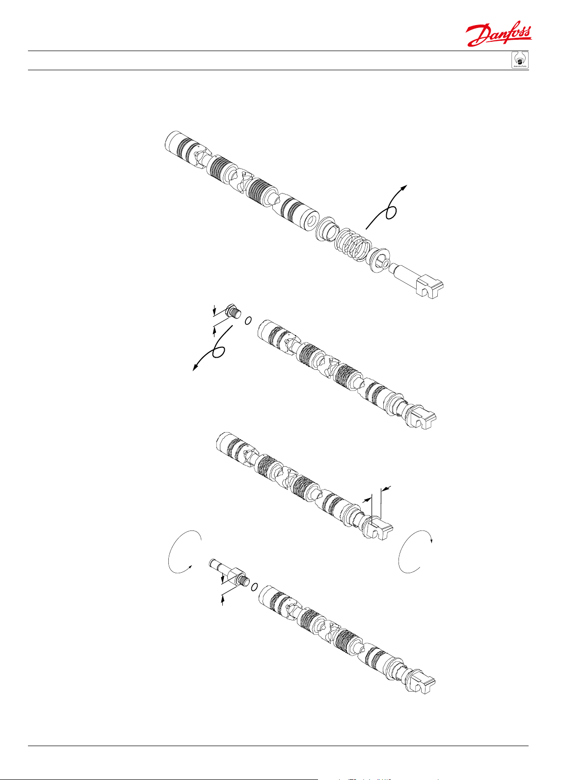
Service and Parts Manual PVG 100 Proportional Valves
Detent
Service parts
PVBS main spool
Friction
detent
10
3
11 mm
Mechanical
float
12 mm
8 Nm
[70 lbf·in]
8 Nm
[70 lbf·in]
9
3
1
Note: Spools must be installed with LS holes
on ‘B’ port side of PVB.
2
12 mm
1
7
8 Nm
[70 lbf·in]
5
1
8 Nm
[70 lbf·in]
4
4
3
4
5
4
3
Main spool
6
8 Nm
[70 lbf·in]
12.5 mm
6
Float
8
11
3
6
B-port
8 Nm
[70 lbf·in]
E101 320E
3
32
520L0888 • Rev BB • Feb 2015

Service and Parts Manual PVG 100 Proportional Valves
Service parts
PVBS main spool
Type Description Code No.
PVBS Standard
PVBS Electric float position, B port
PVBS Mechanical float position, B port
PVBS Friction detent
Item Description Code No.
1 Main spool 1 1 1 1
2 Plug 1 1
3 O-ring, 6.0 x 1.5 [0.24 x 0.06] 2 2 2 2
4 Spring stop, black 2 2
5 Spring 1 1 1
5 Spring, hydraulic actuation 155L7504 1
6 Tension rod 1 1 1 1
7 Spring stop (float position), gold 1 1
8 Bushing (float position) 1 1
9 Float position, B port (item 3 included) 155L9152 1
10 Friction detent (item 3 included) 155L0390 1
11 Spring stop (float position), silver 1 1
E101 321E
520L0888 • Rev BB • Feb 2015
33

Service and Parts Manual PVG 100 Proportional Valves
Service parts
PVM, mechanical activation
4
6
5
8
9
10
9
4 mm
10
8
7.5 Nm
[66 lbf•in]
3 mm
8 Nm
[70 lbf•in]
7
2
10 mm
1
3
8 Nm
[70 lbf•in]
5 mm
34
8 Nm
[70 lbf•in]
13 mm
520L0888 • Rev BB • Feb 2015
6 mm
11
E101 322E

Service and Parts Manual PVG 100 Proportional Valves
Service parts
PVM, mechanical activation
Type Description Angle Code No.
PVM Adjustable 22.5° 157B3171
PVM Adjustable 37.5° 157B3172
PVM Adjustable, without lever and base - 157B3173
PVM Adjustable, without lever 37.5° 157B3174
PVM Adjustable, without lever 22.5° 157B3175
PVM Non-adjustable 22.5° 157B3191
PVM Non-adjustable 37.5° 157B3192
PVM Non-adjustable, without lever and base - 157B3193
PVM Non-adjustable, without lever 37.5° 157B3194
PVM Non-adjustable, without lever 22.5° 157B3195
Item Description Code No.
1 Seal nut 681X8270 2 2 2 2 2
2 Threaded pin 681X0323 2 2 2 2 2
3 Screw, M6 x 15 SHCS 4 4 4 4 4 4 4 4 4 4
4 O-ring, 5.0 x 2.0 [0.2 x 0.08] 2 2 2 2 2 2 2 2 2 2
5 Profile O-ring 1 1 1 1 1 1 1 1 1 1
6 Housing 1 1 1 1 1 1 1 1 1 1
7 Lever with nut 1 1 1 1
8 Base kit, 22.5° 155L3450 1 1 1 1
8 Base kit, 37.5° 1 1 1 1
9 Screw, M5 x 25 SS SHCS 1 1 1 1 1 1 1 1
10 Washer 1 1 1 1 1 1 1 1
11 Base/lever kit, 22.5° 155L3154 1 1
11 Base/lever kit, 37.5° 1 1
Seal kit (includes item 4 and 5) 157B3999 1 1 1 1 1 1 1 1 1 1
E101 323E
520L0888 • Rev BB • Feb 2015
35

Service and Parts Manual PVG 100 Proportional Valves
Service parts
PVH, PVMD, PVMF, and
PVMR covers
19 mm PVMR
11 mm PVMF
4 Nm
[35 lbf•in]
15 Nm
[133 lbf•in]
36mm
26
28
31
30
29
27
24
8 Nm
[70 lbf•in]
PVMR/
PVMF
5 mm
25
22
21
24
35
23
22
PVMD
24
33
22
32
21
PVH
36
E101 324E
520L0888 • Rev BB • Feb 2015

Service and Parts Manual PVG 100 Proportional Valves
Service parts
PVH, PVM, PVMD, PVMF,
and PVMR covers
Type Description Code No.
PVMD Mechanical activated cover 157B0001
Hydraulic activated cover, G 1/4 - thread 157B0008
PVH
Hydraulic activated cover, 9/
PVMR Mechanical detent 157B0015
PVMF Mechanical float 157B0005
Item Description Code No.
21 Profile O-ring 1 1 1
22 O-ring, 5.0 x 2.0 [0.2 x 0.08] 1 1 4 4 1
23 Cover 1
24 Screw, M6 x 15 4 4 4 4 4
25 Cover (PVMF/PVMR) 1
26 O-ring, 19.3 x 2.4 [0.76 x 0.09] (PVMF/PVMR) 1 1
27 Plug (PVMF) 1
27 Plug (PVMR) 1
28 Ball, 5 mm [0.5] (PVMF/PVMR) 3 3
29 Spring (PVMR) 3
29 Spring (PVMF) 3
30 O-ring, 6.0 x 1.5 [0.24 x 0.59] (PVMF) 3
30 O-ring, 14.0 x 2.0 [0.55 x 0.08] (PVMR) 3
31 Plug (PVMF) 3
31 Plug (PVMR) 3
32 O-ring, 21.3 x 2.4 [0.84 x 0.09] 1 1
33 Cover, G
33 Cover, 9/
1
/4 - thread 1
16
- 18 UNF thread 1
35 Sealing plug, G 1/4 - thread 2
35 Sealing plug, 9/
16
- 18 UNF thread 2
Seal kit (includes item 21, 22, 26, 30, and 32) 157B3999 1 1 1 1 1
16
- 18 UNF thread 157B0007
E101 325E
520L0888 • Rev BB • Feb 2015
37

Service and Parts Manual PVG 100 Proportional Valves
Service parts
Electrical activation,
Hirschmann conn.
3
PVEH/PVES
5
6
5 mm
8 Nm
[70 lbf•in ]
PVEO/
PVEO-R
8 Nm
[70 lbf•in ]
5 mm
11
12
13
9
8
7
10
9
4
5
9
11
12
13
9
8
7
38
520L0888 • Rev BB • Feb 2015
10
9
9
E101 326E

Service and Parts Manual PVG 100 Proportional Valves
Service parts
Electrical activation,
Hirschmann conn.
On/O actuation Code No.
On/O, 12 volt, Hirschmann connector 157B4216
PVEO
On/O, 24 volt, Hirschmann connector 157B4228
On/O with ramp, 12 volt, Hirschmann connector 157B4217
PVEO-R
On/O with ramp, 24 volt, Hirschmann connector 157B4229
Proportional actuation Code No.
Standard, active fault monitoring, 11-32 volt, Hirschmann conn. 157B4032
PVEH
Standard, passive fault monitoring, 11-32 volt, Hirschmann conn. 157B4033
Float, active fault monitoring, 11-32 volt, Hirschmann conn. 157B4332
0% hysteresis active fault monitoring, 11-32 volt, Hirschmann conn. 157B4832
PVES
0% hysteresis passive fault monitoring, 11-32 volt, Hirschmann conn. 157B4832
Item Description Code No.
3 Electric plug, DIN 43650, gray, PG 11 984L3286 1 1 1 1 1
4 Electric plug, Din 43650, black, PG 9 984L3156 1 1 1 1
5 Screw, M6 x 33 4 4 4 4 4 4 4 4 4
6 Plug 1 1 1 1 1
7* O-ring, 30.0 x 2.5 [1.18 x 0.10] 1 1 1 1 1 1 1 1 1
8* O-ring, 8.0 x 2.0 [ .35 x 0.08] 1 1 1 1 1 1 1 1 1
9* O-ring. 10.0 x 2.0 [0.39 x 0.08] 3 3 3 3 3 3 3 3 3
10* Filter 1 1 1 1 1 1 1 1 1
11* O-ring, 4.0 x 1.0 [0.16 x 0.04] 3 3 3 3 3 3 3 3 3
12 Check valve 2 2 2 2 2 2 2 2 2
13 Orifice, 1.0 mm [0.04] 1 1 1 1 1
Orifice, 0.8 mm [0.03] 1 1 1 1
Seal kit (includes item 7, 8, 9, 10, and 11) 157B4997 1 1 1 1 1 1 1 1 1
E101 327E
520L0888 • Rev BB • Feb 2015
39

Service and Parts Manual PVG 100 Proportional Valves
Service parts
Electrical activation,
AMP connector
2
5
PVEA/PVEH/PVES
6
5 mm
5 mm
5
8 Nm
[70 lbf•in ]
8 Nm
[70 lbf•in ]
11
12
13
9
8
7
10
9
3
2
5 mm
8 Nm
[70 lbf•in ]
5
9
2
PVEA-DI/
PVEH-DI
6
PVED
40
PVEO/
PVO-R
11
12
10
9
520L0888 • Rev BB • Feb 2015
9
13
11
12
9
8
7
10
9
13
9
8
7
9
E101 332E

Service and Parts Manual PVG 100 Proportional Valves
Service parts
Electrical activation, AMP
connector
On/O actuation Code No.
On/O, 12 volt, AMP connector 157B4901
PVEO
On/O, 24 volt, AMP connector 157B4902
On/O with ramp, 12 volt, AMP connector 157B4903
PVEO-R
On/O with ramp, 24 volt, AMP connector 157B4904
Proportional actuation Code No.
Standard, active fault monitoring, 11-32 volt, AMP conn. 157B4734
PVEA
Standard, passive fault monitoring, 11-32 volt, AMP conn. 157B4735
Standard, active fault monitoring, 11-32 volt, AMP conn. 157B4736
PVEA-DI
Standard, passive fault monitoring, 11-32 volt, AMP conn. 157B4737
Standard, active fault monitoring, 11-32 volt, AMP conn. 157B4034
PVEH
Standard, passive fault monitoring, 11-32 volt, AMP conn. 157B4035
Standard, active fault monitoring, 11-32 volt, AMP conn. 157B4036
PVEH-DI
Standard, passive fault monitoring, 11-32 volt, AMP conn. 157B4037
0% hysteresis active fault monitoring, 11-32 volt, AMP conn. 157B4834
PVES
0% hysteresis passive fault monitoring, 11-32 volt, AMP conn. 157B4835
PVED 0% hyst., passive or acrive fault monitoring, 11-32 volt, AMP 157B4943
Item Description Code No.
2 AMP female connector, gray 157B4992 1 1 1 1 1 1 1 1 1 1 1 1 1 1 1
3 AMP female connector, black 157B4993 1 1 1 1 1 1
5 Screw, M6 x 33 4 4 4 4 4 4 4 4 4 4 4 4 4 4 4
6 Plug 1 1 1 1 1 1 1 1 1 1 1
7 O-ring, 30.0 x 2.5 [1.18 x 0.10] 1 1 1 1 1 1 1 1 1 1 1 1 1 1 1
8 O-ring, 8.0 x 2.0 [ .35 x 0.08] 1 1 1 1 1 1 1 1 1 1 1 1 1 1 1
9 O-ring. 10.0 x 2.0 [0.39 x 0.08] 3 3 3 3 3 3 3 3 3 3 3 3 3 3 3
10 Filter 1 1 1 1 1 1 1 1 1 1 1 1 1 1 1
11 O-ring, 4.0 x 1.0 [0.16 x 0.04] 3 3 3 3 3 3 3 3 3 3 3 3 3 3 3
12 Check valve 2 2 2 2 2 2 2 2 2 2 2 2 2 2 2
13 Orifice, 1.0 mm [0.04] 1 1 1 1 1 1 1 1 1 1 1
Orifice, 0.8 mm [0.03] 1 1 1 1
Seal kit (includes item 7, 8, 9, 10, and 11) 157B4997 1 1 1 1 1 1 1 1 1 1 1 1 1 1 1
E101 333E
520L0888 • Rev BB • Feb 2015
41

Service and Parts Manual PVG 100 Proportional Valves
Seal kits
Seal kits for PVG 100
Module Code No. Page No.
PVM / PVH / PVMD / PVMR / PVMF 157B3999 35, 37
PVEO/PVEA/PVEH/PVES/PVEH-DI/PVED 157B4997 39, 41
PVPV/PVPF/PVB/PVT/PVTI (for each sealing face) 11003451 29, 31
PVPP 35400321 19
PVPE 155G8527 19
P106 300E
42
520L0888 • Rev BB • Feb 2015

Service and Parts Manual PVG 100 Proportional Valves
Notes
520L0888 • Rev BB • Feb 2015
43

Products we oer:
Danf
already on order pr
All trademarks in this material are proper
Danfoss
Building #22, No. 1000 Jin Hai Rd
Danfoss
Power Solutions US Compan
2800 East 13th Street
Ames, IA 50010, USA
Phone:
y Bent Axis Motors
y Closed Circuit Axial Piston
Pumps and Motors
y Displays
y Electrohydraulic Power
Steering
y Electrohydraulics
y Hydraulic Power Steering
y Integrated Systems
y Joysticks and Control
Handles
y Microcontrollers and
Software
y Open Circuit Axial Piston
Pumps
y Orbital Motors
y P LUS+1® GUIDE
y Proportional Valves
y Sensors
y Steering
y Transit Mixer Drives
Danfoss Power Solutions is a global manufacturer and supplier of high-quality hydraulic and
electronic components. We specialize in providing state-of-the-art technology and solutions that
excel in the harsh operating conditions of the mobile o-highway market. Building on our extensive
applications expertise, we work closely with our customers to ensure exceptional performance for a
broad range of o-highway vehicles.
We help OEMs around the world speed up system development, reduce costs and bring vehicles to
market faster.
Danfoss – Your Strongest Partner in Mobile Hydraulics.
Go to www.powersolutions.danfoss.com for further product information.
Wherever o-highway vehicles are at work, so is Danfoss.
We oer expert worldwide support for our customers, ensuring the best possible solutions for
outstanding performance. And with an extensive network of Global Service Partners, we also provide
comprehensive global service for all of our components.
Please contact the Danfoss Power Solution representative nearest you.
Comatrol
www.comatrol.com
Schwarzmüller-Inverter
www.schwarzmuellerinverter.com
Turolla
www.turollaocg.com
Valmova
www.valmova.com
Hydro-Gear
www.hydro-gear.com
Daikin-Sauer-Danfoss
www.daikin-sauer-danfoss.com
+1 515 239 6000
oss can accept no responsibility for possible errors in catalogues, brochures and other printed material. Danfoss reserves the right to alter its products without notice. This also applies to products
520L0888 • Rev BB • Feb 2015
ovided that such alterations can be made without subsequential changes being necessary in specifications already agreed.
Local address:
Danfoss
y
Power Solutions GmbH & Co. OHG
Krokamp 35
D-24539 Neumünster, Germany
Phone: +49 4321 871 0
ty of the respective companies. Danfoss and the Danfoss logotype are trademarks of Danfoss A/S. All rights reserved.
Danfoss
Power Solutions ApS
Nordborgvej 81
DK-6430 Nordborg, Denmark
Phone: +45 7488 4444
Power Solutions
Jin Qiao, Pudong New District
Shanghai, China 201206
Phone: +86 21 3418 5200
 Loading...