

Page 1
Technical Information
PVG 100
Proportional Valve Group
www.danfoss.com
Page 2
Technical Information
PVG 100 Proportional Valve Group
Revision history Table of revisions
Date Changed Rev
April 2021 Changed document number from 'BC00000039' to 'BC152886483475' 0606
September 2018 PVB 100 code numbers table change. 0503
May 2018 Minor change. 0502
March 2016 Updated for Engineering Tomorrow design. 0501
February 2006 - January 2014 Various changes BA - EB
February 2005 New Edition AA
2 | © Danfoss | April 2021 BC152886483475en-000606
Page 3

Technical Information
PVG 100 Proportional Valve Group
Contents
General information
Acronyms.............................................................................................................................................................................................6
General.................................................................................................................................................................................................7
PVG 100 standard oil flow direction/max flow setting..................................................................................................7
PVG 100 valve system................................................................................................................................................................7
General features PVG 100, load independent flow control.........................................................................................7
PVP - pump side module .........................................................................................................................................................8
PVB – basic module.................................................................................................................................................................... 8
Actuation module.......................................................................................................................................................................8
Remote control units ................................................................................................................................................................ 9
Function
PVG 100 with open center PVPF...............................................................................................................................................10
PVG 100 with closed center PVPV / PVPVP / PVPVM.........................................................................................................11
PVG 100 closed center priority steering PVPVP module ........................................................................................... 12
PVG 100 closed center PVPVM module ...........................................................................................................................12
PVG 100 basic modules PVB.......................................................................................................................................................12
PVG 100 tank modules ................................................................................................................................................................13
Load sensing controls...................................................................................................................................................................14
LS control with bleed orifice (do not use with PVG valves).......................................................................................14
Integral PC function.................................................................................................................................................................14
Load sensing system characteristics:.................................................................................................................................14
Remote pressure compensated controls.............................................................................................................................. 15
Remote pressure compensated system characteristics:............................................................................................ 15
PVG 100 main spool with pressure compensated control..............................................................................................15
Pressure compensated system characteristics.............................................................................................................. 16
Typical applications for pressure compensated systems.....................................................................................16
Typical applications for remote pressure compensated systems:..........................................................................16
PVMR, friction detent....................................................................................................................................................................17
PVMF, mechanical float position lock.....................................................................................................................................17
PVBS, main mpools for flow control (standard).................................................................................................................. 17
PVBS, main spools for flow control (with linear characteristic).....................................................................................18
Safety
Building in safety............................................................................................................................................................................19
FMEA (Failure Mode and Effect Analysis) IEC EN 61508............................................................................................. 19
Hazard and risk analysis ISO 12100-1/14121..................................................................................................................19
Example of a control system for manlift................................................................................................................................20
Examples of wiring block diagram.....................................................................................................................................21
Example of fault monitoring.................................................................................................................................................23
PVG 32 – Mainly used in system with fixed displacement pumps..........................................................................24
PVG 100 – Alternative LS dump or pilot supply disconnect..................................................................................... 24
PVG 120 – Pump disconnect/block for variable pumps.............................................................................................24
Technical data
PVG 100 technical data................................................................................................................................................................ 25
PVH, hydraulic actuation.............................................................................................................................................................25
PVG 100 PVM operating force................................................................................................................................................... 26
PVG 100 PVE reaction time and oil consumption.............................................................................................................. 26
PVEO power supply and consumption.............................................................................................................................27
PVEA, PVEH and PVES..............................................................................................................................................................27
Technical characteristics
PVPF, pump side module............................................................................................................................................................28
Open center flow rating.............................................................................................................................................................. 28
Closed center flow rating............................................................................................................................................................28
PVG 100 pressure drop for PVB, basic module....................................................................................................................29
PVB with pressure compensation, closed center PVP...................................................................................................... 30
PVHC characteristic - Spool stroke vs current......................................................................................................................33
Hydraulic systems
©
Danfoss | April 2021 BC152886483475en-000606 | 3
Page 4

Technical Information
PVG 100 Proportional Valve Group
Contents
PVG 100 with variable displacement pump schematic example................................................................................. 34
Electrically actuated PVG 100, variable displacement pump, PVB 100 with integrated pilot operated
check valves............................................................................................................................................................................. 34
Electrically actuated PVG 100/32, fixed displ. pump, PVB 100/32 with integrated pilot operated
check valves............................................................................................................................................................................. 35
Other operating conditions
Oil.........................................................................................................................................................................................................36
Mineral oil....................................................................................................................................................................................36
Non-flammable fluids............................................................................................................................................................. 36
Biodegradable oils....................................................................................................................................................................36
Particle Content, Degree of Contamination.........................................................................................................................36
Filtration............................................................................................................................................................................................ 36
Mounting
Standard mounting vs. option mounting.............................................................................................................................38
Modules and code numbers
PVPF (Open Center) Inlet Modules - for Pumps with Fixed Displacement .............................................................. 39
PVPF Accessories for Pump Side Modules............................................................................................................................39
PVP (Open and Closed) Accessories for Pump Side Modules........................................................................................40
PVPV (Closed Center) Inlet Modules....................................................................................................................................... 40
PVPVP, Closed Center Priority Side Modules - for Pumps with Variable Displacement.......................................41
PVPVM, Closed Center Mid Inlet Modules - for Pumps with Variable Displacement............................................ 41
PVB 100 Basic Modules (Standard Spools)............................................................................................................................42
PVB 100 Basic Modules (Exposed spools)..............................................................................................................................42
PVB 100 Basic Modules (High Flow Spools)..........................................................................................................................43
PVG 100 PVM code numbers..................................................................................................................................................... 43
PVM / PVH, Covers......................................................................................................................................................................... 43
PVEO, ON/OFF Actuation............................................................................................................................................................ 44
PVHC - main spool control.................................................................................................................................................... 44
PVEA/PVEH/PVES, Proportional Actuation............................................................................................................................44
PVLA, Anti-Cavitation Valve Fitted into PVB.........................................................................................................................45
PVLP, Shock / Anti-Cavitation Valve Fitted into PVB......................................................................................................... 46
PVT 100, Tank Module..................................................................................................................................................................46
PVTI 100/32, Interface Module*................................................................................................................................................ 47
PVG 100 PVSI / PVT, Assembly Kit.............................................................................................................................................47
PVBE (End Bodies), Assembly Kit.............................................................................................................................................. 47
PVG 100 / PVTI, Interface Module Assembly Kit..................................................................................................................47
PVB 32, Assembly Kit.....................................................................................................................................................................47
PVG 32 Basic Modules with T0, PVBZ (Compatible with PVG 100)...............................................................................48
PVG 32 Basic Modules with T0, PVB (Compatible with PVG 100)................................................................................. 49
Standard Spools for Electrical and Mechanical Actuation Progressive Flow Characteristics.............................50
Standard Spools for Hydraulic Actuation Progressive Flow Characteristics.............................................................50
Spools for Friction Detent, PVMR (not compatible with PVBZ 100) Progressive Flow Characteristics...........51
Spools for Mechanical Float position, PVMF (not compatible with PVBZ 100) Progressive Flow
Characteristics......................................................................................................................................................................... 51
Standard Spools (Electrical and Mechanical Actuation) Linear Flow Characteristics............................................51
Standard Spools (Electrical and Mechanical Actuation) Throttled Open in Neutral, Linear Flow
Characteristics......................................................................................................................................................................... 52
Standard Spools (Hydraulic and Mechanical Actuation), Throttled Open in Neutral, Linear Flow
Characteristics......................................................................................................................................................................... 52
Standard Spools (Electrical and Mechanical Actuation), Full Open in Neutral; Progressive Flow
Characteristics ........................................................................................................................................................................ 52
Standard Spools (Hydraulic and Mechanical Actuation), Full Open in neutral; Linear Flow
Characteristics ........................................................................................................................................................................ 52
High Flow Spools (Electrical and Mechanical Actuation) Progressive Flow Characteristics...............................53
High Flow Spools (Hydraulic and Mechanical Actuation) Progressive Flow Characteristics..............................53
High Flow Spools, Full Open A/B → T and Neutral; Progressive Flow Characteristics ........................................ 54
Exposed spools Progressive Flow Characteristics..............................................................................................................54
4 | © Danfoss | April 2021 BC152886483475en-000606
Page 5

Technical Information
PVG 100 Proportional Valve Group
Contents
Dimensions
PVG 100 dimensions in general................................................................................................................................................55
PVG 100 with open center PVPF dimensions.......................................................................................................................56
PVG 100/32, closed center PVPV.............................................................................................................................................. 57
PVG 100, Closed Center PVP with Integrated Priority Valve ..........................................................................................58
Examples........................................................................................................................................................................................... 59
Module selection chart
Exploded view for module selection ..................................................................................................................................... 64
PVG 100 order specification
Please state.......................................................................................................................................................................................69
Standard and option assembly.................................................................................................................................................69
Reordering........................................................................................................................................................................................70
Specification sheet
Specification form..........................................................................................................................................................................71
Specification example for PVPVM............................................................................................................................................72
©
Danfoss | April 2021 BC152886483475en-000606 | 5
Page 6
Technical Information
PVG 100 Proportional Valve Group
General information
Acronyms
This table provides a definition of some commonly used terms
PVG = Proportional Valve Group
PVAS Assembly (Tie Rod) Kit
PVB Basic Module (Body)
PVBE Basic End Module (Body)
PVBO Basic Open Ended Module (Body)
PVBS Main Spool for PVB
PVBSO Main Spool for PVBO
PVBZ Basic Module (Body) Zero Leak
PVE Electrical Actuator
PVEA Electrical Actuator-Fine Proportional
PVED Electrical Actuator-Digital
PVEH Electrical Actuator-High Proportional
PVEO Electrical Actuator-ON/OFF
PVES Electrical Actuator-Super Proportional
PVH Cover for Hydraulic Actuation
PVHC Electrical Actuator-High Current
PVLA Anti-Cavitation Valve
PVLP Shock Valve
PVM Mechanical Actuator
PVMD Cover for Mechanical Activation
PVMF Cover for Mechanical Float
PVMR Cover for Friction Detent
PVP Pump Side Module (Inlet)
PVPC Plug for external pilot oil supply
PVPD Open Center PVPF Dummy Spool
PVPE Electrical Unloading Valve for PVPF
PVPF Open Center PVP
PVPH Hydraulic Unloading Valve for PVPF
PVPP Electrical Pilot Shut-Off Valve
PVPV Closed Center PVP
PVPV/M Pump side module
PVPVP Closed Center PVP w/Priority
PVPX, LS LS Unloading valve
PVT Tank Side Module
PVTI Interface Module
6 | © Danfoss | April 2021 BC152886483475en-000606
Page 7

PVEH/PVES
PVEA
PVEO
PVH
PVMD
PVMR/PVMF
PVP
PVM
PVB
PVT
B
A
P-A
P-B
7-9 N•m
[61-79 lbf•in]
Q max: P B
Q max: P A
Technical Information
PVG 100 Proportional Valve Group
General information
General
PVG 100 standard oil flow direction/max flow setting
Adjustment screws are used to change the amount of oil flowing from ports P to B or P to A.
PVM to the right of PVP
PVG 100 valve system
PVG 100 is a hydraulic load sensing valve, designed to fulfill efficiency requirements.
From a simple load sensing directional valve to an advanced electrohydraulic controlled load
independent proportional valve the PVG 100 modular system makes it possible to build up a valve group
to fulfill customer requirements. The compact external dimensions of the valve remain unchanged
whatever combination is specified.
General features PVG 100, load independent flow control
Flow sharing for maximum controllability and safety
•
Load-independent flow control for precise operation and improved productivity
•
Oil flow to an individual function is independent of the load pressure of this function regardless of
‒
sufficient or insufficient pump flow.
Oil flow to one function is independent of the load pressure of other functions regardless of
‒
sufficient or insufficient pump flow.
Load-sensing technology for higher efficiency, safety, reduced energy consumption, and longer
•
system lifetime
Configurable as an advanced electrical, hydraulic or mechanically operated proportional load-sensing
•
valve
Open spool-ends for system integrating mechanical cable or linkage actuation
•
©
Danfoss | April 2021 BC152886483475en-000606 | 7
Page 8

Technical Information
PVG 100 Proportional Valve Group
General information
Modular design providing a wide range of configuration possibilities
•
Up to eight different sections per valve group (maximum flow per section: 240 l/min [63.4 gal/min])
•
Can be configured in combination with PVG 32 (with T0) for maximum flexibility (up to 20 basic valve
•
modules per valve group)
Optimized return flow characteristics, which minimizes pressure loss
•
Low weight
•
Compact design and installation
•
BSP and UNF connection threads
•
PVP - pump side module
Build in load sense relief valve
•
System pressure up to 350 bar (5075 psi)
•
Full Flow dump valve (open center only)
•
Pilot supply shut off (optional) ••Accumulator gauge connection
•
Pressure gauge connection
•
Pilot gauge connection
•
Integrated pilot supply valve
•
Versions:
•
Open center version for systems with fixed displacement pumps
‒
Closed center versions for systems with variable displacement pump
‒
Integrated priority valve for dynamic steering integration
‒
PVB – basic module
Integrated pilot operated check valves in A and B work ports for low internal leakage
•
Integrated pressure compensator
•
Interchangeable spools
•
Single and Dual Shock/suction valves for A and B ports
•
Different interchangeable spool variants
•
All versions suitable for mechanical, hydraulic and electrical actuation
•
Versions:
•
PVG100-HF (High Flow) version for less total pressure loss at increased flow
‒
End module version for extra space savings
‒
Open spool-end version for extended mechanical actuation possibilities
‒
Actuation module
The basic module is always fitted with mechanical actuator PVM, which can be combined with the
following as required:
Electrical actuator (11 – 32 V
•
PVES – proportional, Super
‒
PVEH – proportional, high performance
‒
PVEH-F – proportional high performance, Float
‒
PVEA – proportional low hysteresis (not recommended for PVG 100-HF High Flow)
‒
PVEM – proportional, medium performance
‒
PVEO – ON/OFF
‒
PVEU – proportional, voltage control, 0-10 V
‒
AC/DC
):
8 | © Danfoss | April 2021 BC152886483475en-000606
Page 9
PVRE, electrical control unit, 162F…
Prof 1, 162F…
PVREL, electrical control unit, 155U…
PVRES, electrical control unit, 155B…
PVRH, hydraulic control unit, 155N…
155N0003 155N0001 155N0004 155N0005 155N0002
Technical Information
PVG 100 Proportional Valve Group
General information
PVED-CC – Digital CAN controlled J1939/ISOBUS
‒
PVED-CX – Digital CAN controlled CAN open extra vehicle system safety
‒
PVEP – PVM controlled (11-32 V)
‒
PVHC – High Current actuator for PVG
‒
PVMD, cover for Mechanical actuation
•
PVMR, cover for Mechanical detent (not compatible with PO check modules)
•
PVMF, cover for Mechanical Float (not compatible with PO check modules)
•
PVH, cover for Hydraulic actuation.
•
Remote control units
Electrical remote control units:
•
‒
PVRE, PVRET
‒
PVREL
‒
PVRES
‒
Prof 1
‒
Prof 1 CIP
‒
JS120
Hydraulic remote control unit: PVRHH
•
Electrical and hydraulic remote control units
‒
JS1000 Ball grip
‒
JS1000 PRO grip
‒
JS2000
‒
JS6000
‒
JS7000
©
Danfoss | April 2021 BC152886483475en-000606 | 9
Page 10

Technical Information
PVG 100 Proportional Valve Group
Function
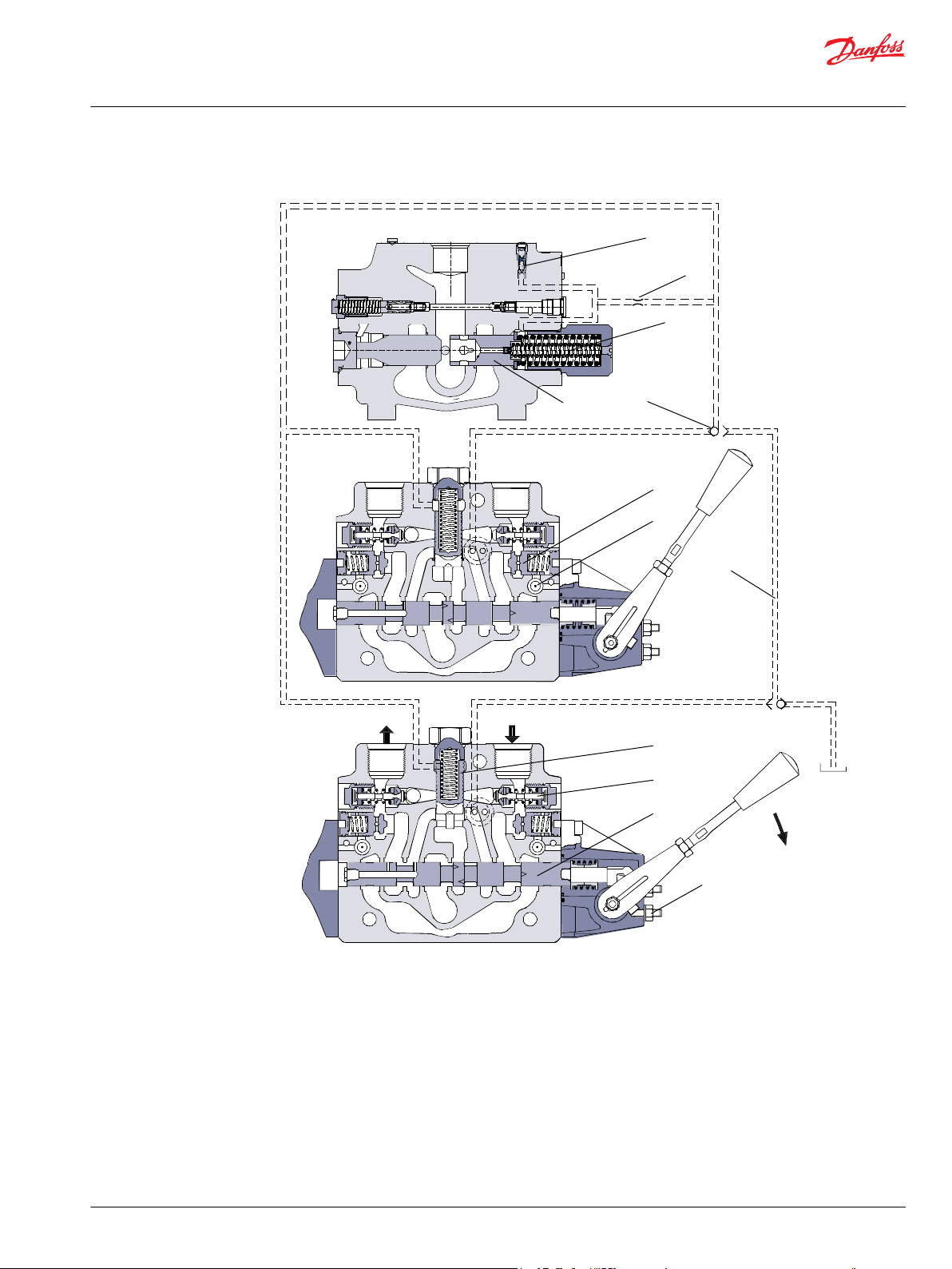
PVG 100 with open center PVPF
When the pump is started and the main spools in the individual basic modules are in the neutral position,
oil flows from the pump, through connection P, across the pressure matching spool (11) to tank. The oil
flow led across the pressure matching spool determines the pump pressure (stand-by pressure).
When one or more of the main spools are actuated, the highest load pressure is fed through the shuttle
valve circuit (4, 7) to the spring chamber (10) behind the pressure matching spool, and completely or
partially closes the connection to tank. Pump pressure is applied to the opposite side of the pressure
matching spool. The pressure relief valve (1) will open should the load pressure exceed the set value,
diverting pump flow back to tank.
Optional PVPC with check valve option may be used in systems where it is necessary to operate the PVG
100 valve by means of the electrical remote control without pump flow.
For additional information about PVPC refer to the publication BC152886483664.
Optional electrically actuated pilot shut off valve PVPP provides additional functional system safety by
removing pilot oil from the electrical actuation or hydraulic actuation system, disabling main spool
actuation. When the PVPP is used with the PVBZ P.O. check valve system it is possible to disable actuation
during mechanical actuation
10 | © Danfoss | April 2021 BC152886483475en-000606
Page 11
B A
B A
B
9
8
7
6
3
5
4
T T
P
T T
P
1
10
12
11
2
T
P
P
Port
PVPD / PVPE
Facility
Pilot
Supply
Pressure Matching
Spool
Technical Information
PVG 100 Proportional Valve Group
Function
PVG 100 sectional view PVP with open center
1 – LS relief valve 7 – Shock and suction valve, PVLP
2 – Shuttle valve 8 – Main spool, PVBS
3 – Pilot operated check valve, POC 9 – Max. oil flow adjustment screws for ports A and B
4 – LS line 10 – Spring 12 or 20 bar
5 – Logic cartridge for POC 11 – Pressure matching spool
6 – Pressure compensator 12 – Orifice
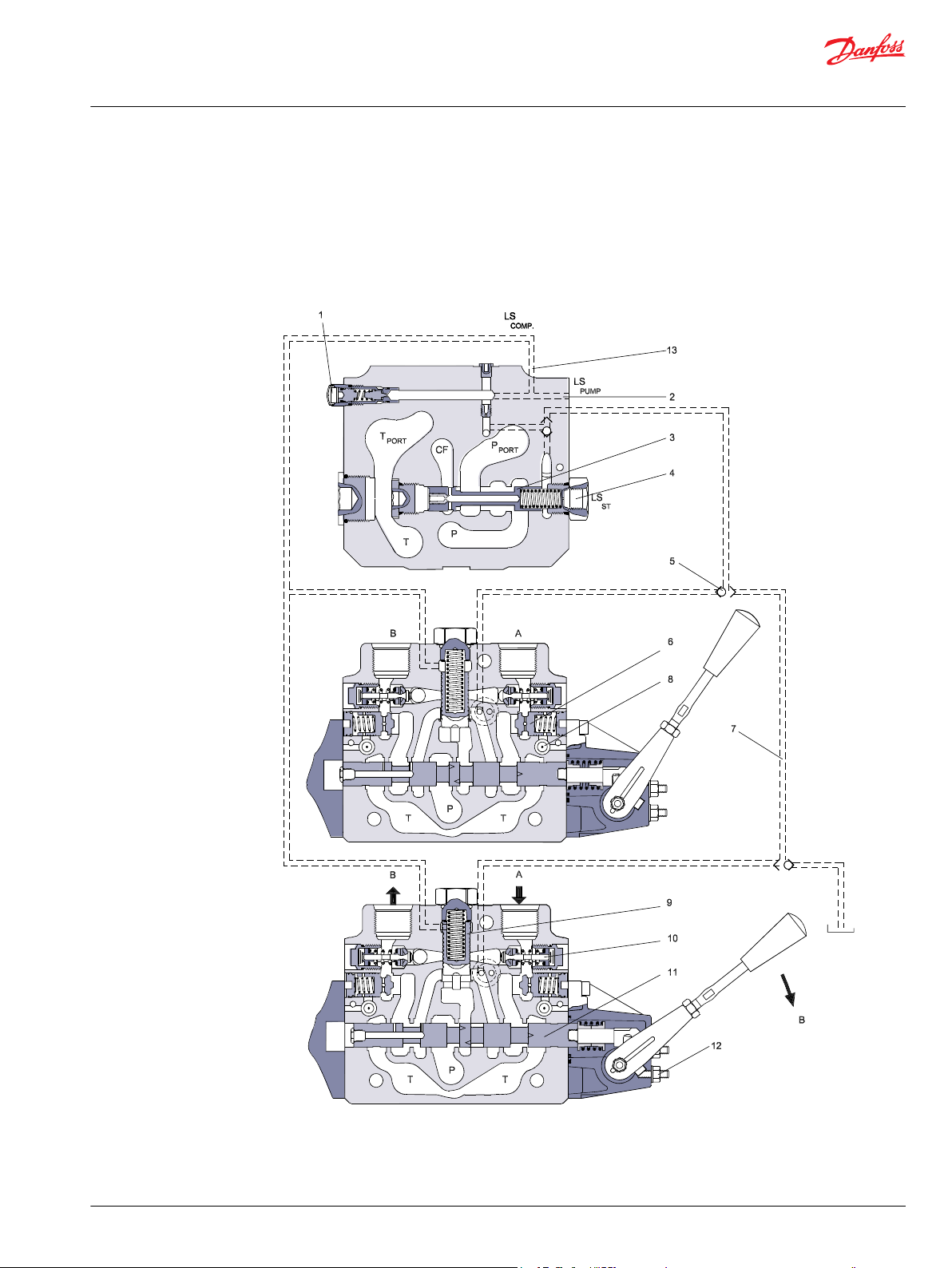
PVG 100 with closed center PVPV / PVPVP / PVPVM
In load sensing systems the load pressure is led to the pump control via the LS connection (2 in the
diagram below). When the work functions are in the spring neutral position the LS pressure is drained to
©
Danfoss | April 2021 BC152886483475en-000606 | 11
Page 12
Technical Information
PVG 100 Proportional Valve Group
Function
tank via the PVG valve. In this condition the pump control sets the displacement so that leakage in the
system is compensated for, to maintain the set stand-by pressure (pump margin). When a main spool is
actuated the pump control will adjust the displacement so that the set differential pressure between P
and LS is maintained.
The PVG100 Inlet LS relief valve (1) is specifically designed to ensure a constant margin pressure across
the main spool, providing demanded regulated flow during maximum load pressure conditions. This
relief adjustment is critical when there are two or more functions being operated together. An incorrectly
adjusted Inlet relief could result in a vast reduction in regulated flow from the adjacent functions that
operate at a lower load pressure. To accurately adjust the inlet LS relief, the pump standby pressure must
be known in addition to the maximum operating load pressure.
Example
Pressure comp pressure level 172 bar [2500 psi]
LS standby pressure requirement that delivers the desired flow -20 bar [-290 psi]
Maximum load pressure requirement 152 bar [2210 psi]
Inlet relief pressure setting 152 bar [2210 psi]
Optional PVPC with check valve option may be used in systems where it is necessary to operate the PVG
100 valve by means of the electrical remote control without pump flow.
For additional information about PVPC refer to publication BC152886483664.
Optional electrically actuated pilot shut off valve PVPP provides additional functional system safety by
removing pilot oil from the electrical actuation or hydraulic actuation system, disabling main spool
actuation. When the PVPP is used with the PVBZ P.O. check valve system it is possible to disable actuation
during mechanical actuation.
PVG 100 basic modules PVB
PVG 100 closed center priority steering PVPVP module
The priority steering version of the PVPV will accommodate pump flows up to 250 l/min [66 US gal/min]
and Control Flow (CF) up to 60 l/min [16 US gal/min] for dynamic steering systems. Additional return port
is included with the PVPVP module.
PVG 100 closed center PVPVM module
The mid-inlet version of the PVPV will accommodate pump flows up to 400 l/min [106 US gal/min]
providing greater efficiency and flexibility when combined with standard and high flow work function
modules.
In the pressure-compensated basic module the compensator (9) maintains a constant pressure drop
across the main spool (11) - both when the load changes and when a module with a higher load pressure
is actuated.
Besides independent flow the other advantage of post-compensated work sections is the ability to
control multifunction operation when flow demand exceeds pump capacity. This means that all work
sections will continue to function regardless of differences in their load and regardless of the pump flow.
The flow relationships specified between functions will be maintained over the full flow range of the
pump.
The shock valves PVLP (10) with fixed setting and the suction valves PVLA on ports A and B are used for
the protection of the individual working function against intermittent pressure overload and/or
cavitation. Optional facilities for dual shock valves for ports A and B provide extra passage area reducing
pressure drop for anti-cavitation applications.
Pilot operated check valve system PVBZ option (6, 8) on ports A and B are uses to reduce the work port to
tank leakage eliminating the need for external actuator load holding in non-critical load holding
applications. All PVG 100 modules contain an integrated T0 drain system to insure optimal performance
12 | © Danfoss | April 2021 BC152886483475en-000606
Page 13
Technical Information
PVG 100 Proportional Valve Group
Function
for PVBZ and all electrical actuation offerings. T0 is most effective when connected directly to the
hydraulic system reservoir independent of the main Tank return system.
PVG 100 tank modules
Designed for low pressure drop at high return flows all PVT modules include facilities for PVLP shock
valves insuring pressure passage spike protection during pump starvation recovery.
1 – LS relief valve 8 – Logic cartridge for POC
2 – LS connection 9 – Pressure compensator
©
Danfoss | April 2021 BC152886483475en-000606 | 13
Page 14
0
0
P101 968E
PC setting
Flow
Pressure
Q max
P101 967
Technical Information
PVG 100 Proportional Valve Group
Function
3 – Priority spool for CF 10 – Shock and suction valve, PVLP
4 – LS connection for steering unit 11 – Main spool, PVBS
5 – Shuttle valve 12 – Max. oil flow adjustment screws for ports A and B
6 –Pilot operated check valve, POC 13 – LS comp (LS signal sent back to compensators)
7 – LS line
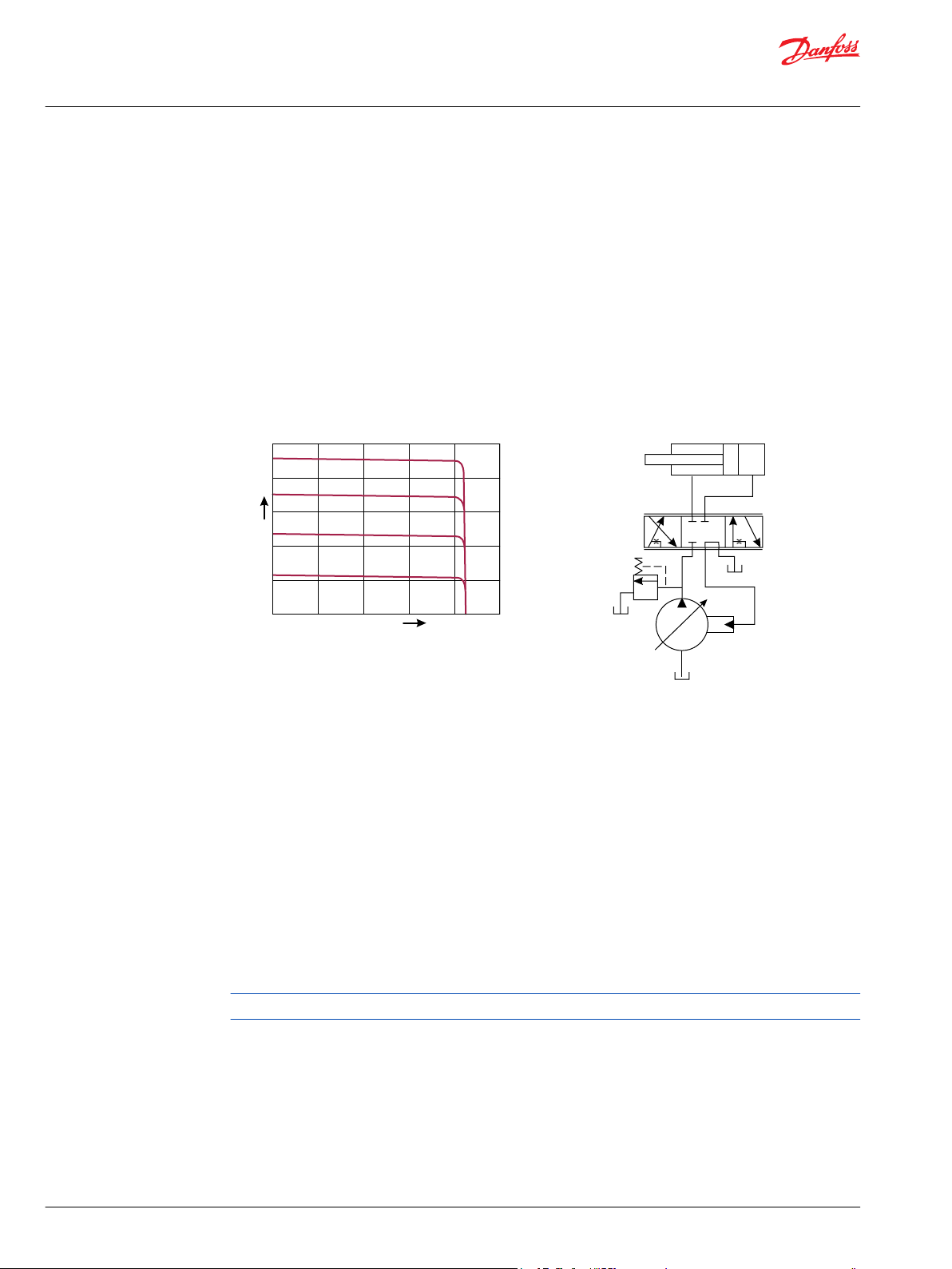
Load sensing controls
The LS control matches system requirements for both pressure and flow in the circuit regardless of the
working pressure. Used with a closed center control valve, the pump remains in low-pressure standby
mode with zero flow until the valve is opened. The LS setting determines standby pressure.
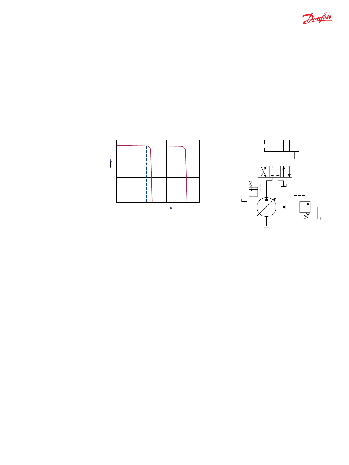
Typical operating curve
Load sensing circuit
Most load sensing systems use parallel, closed center, control valves with special porting that allows the
highest work function pressure (LS signal) to feed back to the LS control.
Margin pressure is the difference between system pressure and the LS signal pressure. The LS control
monitors margin pressure to read system demand. A drop in margin pressure means the system needs
more flow. A rise in margin pressure tells the LS control to decrease flow.
LS control with bleed orifice (do not use with PVG valves)
The load sense signal line requires a bleed orifice to prevent high-pressure lockup of the pump control.
Most load-sensing control valves include this orifice. An optional internal bleed orifice is available, for use
with control valves that do not internally bleed the LS signal to tank.
Integral PC function
The LS control also performs as a PC control, decreasing pump flow when system pressure reaches the PC
setting. The pressure compensating function has priority over the load sensing function.
For additional system protection, install a relief valve in the pump outlet line.
Load sensing system characteristics:
Variable pressure and flow
•
Low pressure standby mode when flow is not needed
•
System flow adjusted to meet system requirements
•
14 | © Danfoss | April 2021 BC152886483475en-000606
Page 15
0
0
Q max
Pressure
Fl
ow
P101 969E
PC setting
Remote PC setting
P101 966
Technical Information
PVG 100 Proportional Valve Group
Function
Lower torque requirements during engine start-up
•
Single pump can supply flow and regulate pressure for multiple circuits
•
Quick response to system flow and pressure requirements
•
Remote pressure compensated controls
The remote PC control is a two-stage control that allows multiple PC settings. Remote PC controls are
commonly used in applications requiring low and high pressure PC operation.
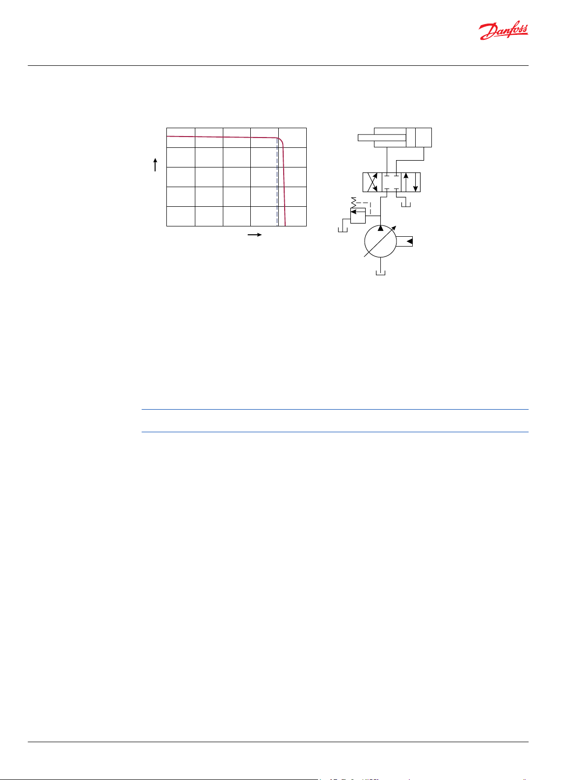
Typical operating curve
Closed center circuit with remote PC
The remote PC control uses a pilot line connected to an external hydraulic valve. The external valve
changes pressure in the pilot line, causing the PC control to operate at a lower pressure. When the pilot
line is vented to reservoir, the pump maintains pressure at the load sense setting.
When pilot flow is blocked, the pump maintains pressure at the PC setting. An on-off solenoid valve can
be used in the pilot line to create a low-pressure standby mode. A proportional solenoid valve, coupled
with a microprocessor control, can produce an infinite range of operating pressures between the low
pressure standby setting and the PC setting.
Size the external valve and plumbing for a pilot flow of 3.8 l/min [1 US gal/min]. For additional system
protection, install a relief valve in the pump outlet line.
Remote pressure compensated system characteristics:
Constant pressure and variable flow
•
High or low pressure standby mode when flow is not needed
•
System flow adjusts to meet system requirements
•
Single pump can provide flow to multiple work functions
•
Quick response to system flow and pressure requirements
•
PVG 100 main spool with pressure compensated control
The PC control maintains constant system pressure in the hydraulic circuit by varying the output flow of
the pump. Used with a closed center control valve, the pump remains in high pressure standby mode at
the PC setting with zero flow until the function is actuated.
©
Danfoss | April 2021 BC152886483475en-000606 | 15
Page 16
0
0
Q max
Pressure
Fl
ow
P101 166E
PC setting
P101 965
Technical Information
PVG 100 Proportional Valve Group
Function
Typical operating curve
Once the closed center valve is opened, the PC control senses the immediate drop in system pressure
and increases pump flow by increasing the swashplate angle.
The pump continues to increase flow until system pressure reaches the PC setting. If system pressure
exceeds the PC setting, the PC control reduces the swashplate angle to maintain system pressure by
reducing flow.
The PC control continues to monitor system pressure and changes swashplate angle to match the output
flow with the work function pressure requirements.
If the demand for flow exceeds the capacity of the pump, the PC control directs the pump to maximum
displacement. In this condition, actual system pressure depends on the actuator load.
Simple closed-center circuit
For additional system protection, install a relief valve in the pump outlet line. * Do not use the PVG 32
with bleed down load sense control.
Pressure compensated system characteristics
Constant pressure and variable flow
•
High pressure standby mode when flow is not needed
•
System flow adjusts to meet system requirements
•
Single pump can provide flow to multiple work functions
•
Quick response to system flow and pressure requirements
•
Typical applications for pressure compensated systems
Constant force cylinders (bailers, compactors, refuse trucks)
•
On/off fan drives
•
Drill rigs
•
Sweepers
•
Trenchers
•
Typical applications for remote pressure compensated systems:
Modulating fan drives
•
Anti-stall control with engine speed feedback
•
Front wheel assist
•
16 | © Danfoss | April 2021 BC152886483475en-000606
Page 17
Technical Information
PVG 100 Proportional Valve Group
Function
Road rollers
•
Combine harvesters
•
Wood chippers
•
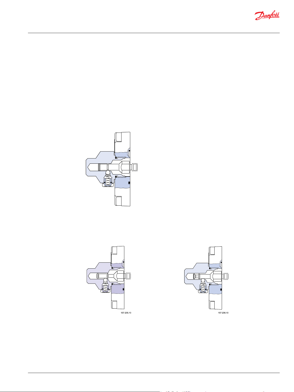
PVMR, friction detent
The friction detent PVMR allows the directional spool to be held in any position, resulting in infinitely
variable, reversible, pressure compensated flow.
This can be sustained indefinitely without having to continue to hold the mechanical lever. Friction
detent spool position may be affected by high differential actuator flow forces and system vibration
resulting in work function flow reduction.
PVMR, friction detent
PVMF, mechanical float position lock
Allows the float spool to be held in the float position after release of the mechanical handle.
PVMF, standard mount only
P → A → F (Push-in)
PVBS, main mpools for flow control (standard)
With post-compensated valves, the A and B work port flow will depend on the pressure drop across the
main spool PVBS.
In open center systems, this pressure drop (standby-pressure) is determined by the volume of fixed pump
flow led to tank across the pressure adjusting spool in the inlet PVPF and the pressure adjusting spool
PVMF, optional mount only
P → A → F (Pull-out)
©
Danfoss | April 2021 BC152886483475en-000606 | 17
Page 18

Technical Information
PVG 100 Proportional Valve Group
Function
bias spring pressure. Since the pressure drop varies with pump flow volume led to tank, the A and B work
port flow will vary.
In closed center systems, the pressure drop across the main spool equals the standby setting of the
pump, measured at the P-port of the valve. The A and B work port flow will remain unchanged as long as
the standby is unchanged.
PVBS, main spools for flow control (with linear characteristic)
PVBS main spools with linear characteristic deliver a higher flow gain directly proportional to the linear
spool travel beyond the dead band.
18 | © Danfoss | April 2021 BC152886483475en-000606
Page 19

W
Technical Information
PVG 100 Proportional Valve Group
Safety
Building in safety
All makes and all types of control valves (including proportional valves) can fail. Thus the necessary
protection against the serious consequences of function failure should always be built into the system.
For each application an assessment should be made for the consequences of pressure failure and
uncontrolled or blocked movements.
To determine the degree of protection that is required to be built into the application, system tools such
an FMEA (Failure Mode and Effect Analysis) and Hazard and Risk Analysis can be used.
FMEA (Failure Mode and Effect Analysis) IEC EN 61508
FMEA is a tool used for analyzing potential risks. This analytical technique is utilized to define, identify,
and prioritize the elimination or reduction of known and/or potential failures from a given system before
it is released for production.
Please refer to IEC FMEA Standard 61508.
Hazard and risk analysis ISO 12100-1/14121
This analysis is a tool used in new applications as it will indicate whether there are special safety
considerations to be meet according to the machine directives EN 13849.
Dependent on the determined levels conformety this analysis will determine if any extra requirements
for the product design, development process, production process or maintenance, i.e. the complete
product life cycle.
Warning
All makes/brands and types of directional control valves – inclusive proportional valves – can fail and
cause serious damage. It is therefore important to analyze all aspects of the application.
Because the proportional valves are used in many different operation conditions and applications, the
manufacturer of the application is alone responsible for making the final selection of the products – and
assuring that all performance, safety and warning requirements of the application are met.
The process of choosing the control system – and safety levels – is governed by the machine directives
EN 13849 (Safety related requirements for control systems).
©
Danfoss | April 2021 BC152886483475en-000606 | 19
Page 20
W
Technical Information
PVG 100 Proportional Valve Group
Safety
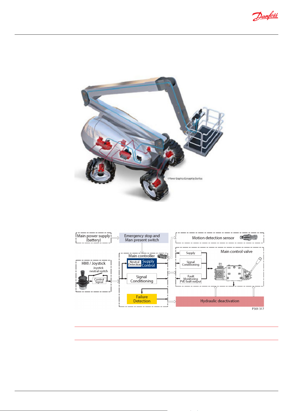
Example of a control system for manlift
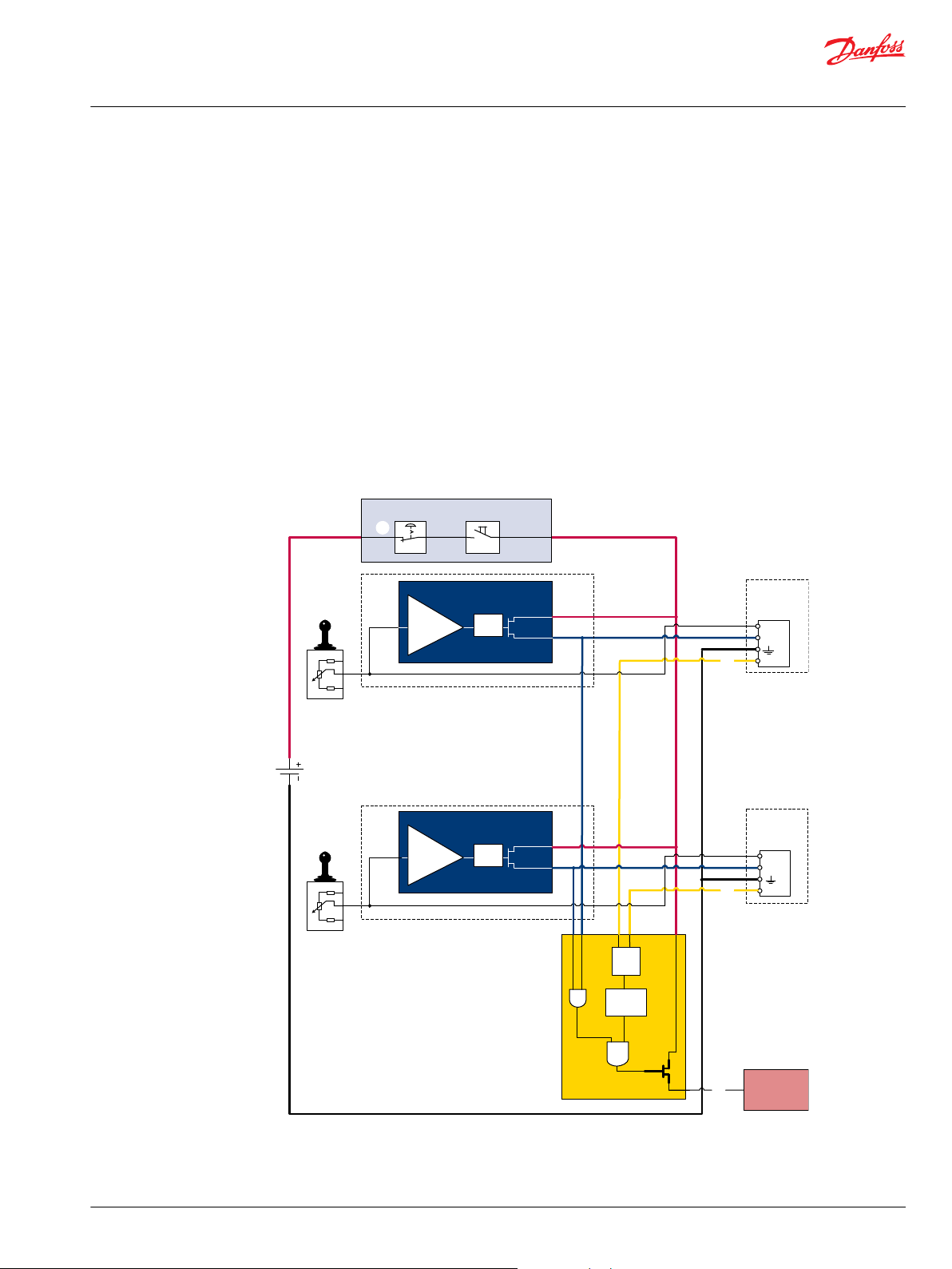
Example of a control system for man-lift
Example of a control system for man-lift using PVE Fault monitoring input signals and signals from
external sensors to ensure the PLUS+1® main controllers correct function of the man-lift.
Typical PVE wiring block diagram
Warning
It is the responsibility of the equipment manufacturer that the control system incorporated in the
machine is declared as being in conformity with the relevant machine directives.
20 | © Danfoss | April 2021 BC152886483475en-000606
Page 21
Fault detection output
high=on
low=off
Alarm
logic
2)
Memory3)
E1
E2
Output
AND
OR
U
DC2
Error
U
S
Neutral detection / Supply control
signal
≠
neutral
OFF
Delay
1)
U
DC2
Error
U
S
PVEH
with AMP
connector
PVEH
with AMP
connector
Hydraulic
deactivation
Neutral detection / Supply control
signal
≠
neutral
OFF
Delay
1)
PVE 1
PVE 2
Emergency
stop
Man present
switch
C
C
D
B
B
A
P301 318
Technical Information
PVG 100 Proportional Valve Group
Safety
PVG 32 – used in system with fixed displacement pumps:
•
PVSK, commonly used in crane application - full flow dump
•
PVPX, LS dump to tank
PVG 100 – alternative LS dump/pilot supply disconnect:
•
PVPP, pilot oil supply shut off
•
External cartridge valve connecting LS pressure or main pressure to tank
PVG 120 – pump disconnect/block for variable pumps:
•
PVPE, full flow dump for the PVG 120
•
External cartridge valve connecting LS pressure to tank
Examples of wiring block diagram
Example 1
Typical wiring block diagram using PVEH with neutral power off switch and fault monitoring output for
hydraulic deactivation.
©
Danfoss | April 2021 BC152886483475en-000606 | 21
Page 22
W
Neutral detection / Supply control
signal
≠
neutral
OFF
Delay
1)
Fault detection output
PVEH-DI
AMP supply
connector
PVEH-DI
AMP supply
connector
PVEH-DI
AMP connector
PVEH-DI
AMP connector
AND
high=on
low=off
Neutral detection / Supply control
signal
≠
neutral
OFF
Delay
1)
PVE 1
PVE 2
Fault detection
Delay
DI
Logic
Memory
U
S
DI-A
DI-B
2)
4)
3)
Output
Fault detection
Delay
DI
Logic
Memory
U
S
DI-A
DI-B
2)
4)
3)
Output
OR
Emergency
Stop
Man present
switch
P301 319
U
DC2
Error
U
S
DI-B
Error
DI-A
U
DC2
Error
U
S
Error
DI-A
Hydraulic
deactivation
W
Technical Information
PVG 100 Proportional Valve Group
Safety
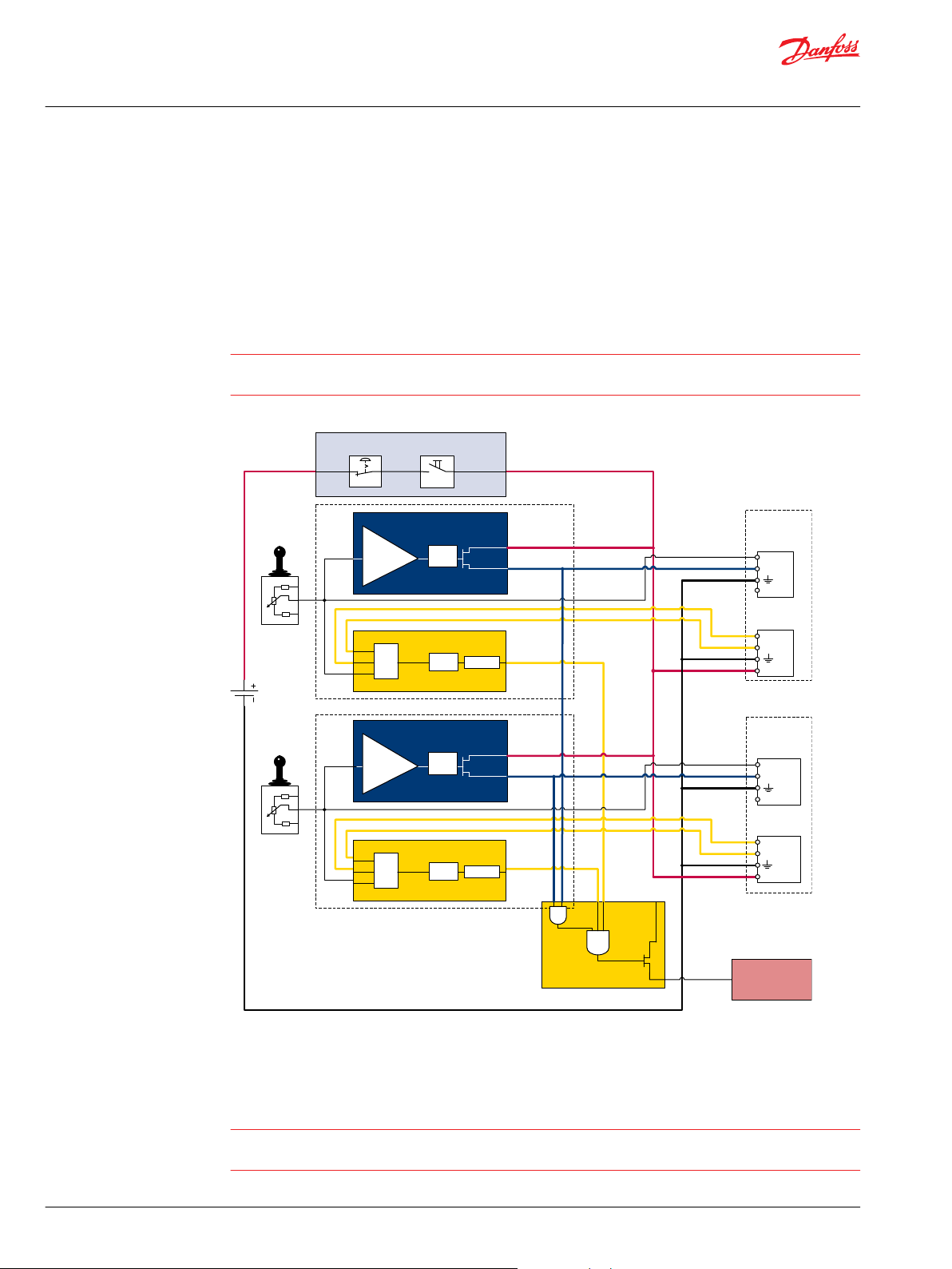
A Emergency stop / man present switch
B PVE Fault monitoring signals
C Neutral signal detection
D Deactivation of the hydraulic system (System Control Logic, example: PLUS+1® for signal monitoring
and triggering signal)
Warning
It is the responsibility of the equipment manufacturer that the control system incorporated in the
machine is declared as being in conformity with the relevant machine directives.
Example 2
Fault monitoring for deactivation of the hydraulic system with extra fault inputs using the PVE’s with DI
(Direction Indication) function. System Control Logic, example PLUS+1® for signal monitoring and
triggering signal for deactivation of the hydraulic system.
Warning
It is the responsibility of the equipment manufacturer that the control system incorporated in the
machine is declared as being in conformity with the relevant machine directives.
22 | © Danfoss | April 2021 BC152886483475en-000606
Page 23

Neutral detection / Supply control
signal
≠
neutral
OFF
Delay
1)
Fault detection output
PVEH-DI
AMP supply
connector
PVEH-DI
AMP supply
connector
PVEH-DI
AMP connector
PVEH-DI
AMP connector
AND
high=on
low=off
Neutral detection / Supply control
signal
≠
neutral
OFF
Delay
1)
PVE 1
PVE 2
Fault detection
Delay
DI
Logic
Memory
U
S
DI-A
DI-B
2)
4)
3)
Output
Fault detection
Delay
DI
Logic
Memory
U
S
DI-A
DI-B
2)
4)
3)
Output
OR
Emergency
Stop
Man present
switch
P301 319
U
DC2
Error
U
S
DI-B
Error
DI-A
U
DC2
Error
U
S
Error
DI-A
Hydraulic
deactivation
W
Technical Information
PVG 100 Proportional Valve Group
Safety
Example of fault monitoring
Similar to previous example using fault monitoring for deactivation of the hydraulic system with extra
fault inputs using the PVE’s with DI (Direction Indication) function.
Example of fault monitoring for deactivation of the hydraulic system
System Control Logic e.g. PLUS+1® for signal monitoring and triggering signal for deactivation of the
hydraulic system.
Warning
It is the equipment manufacturers responsibility to ensure that the control system incorporated in the
©
Danfoss | April 2021 BC152886483475en-000606 | 23
machine is declared as being in conformity with the relevant machine directives.
Other non-electrical modules which can be used in connection with hydraulic deactivation at different
levels.
Page 24

Technical Information
PVG 100 Proportional Valve Group
Safety
PVG 32 – Mainly used in system with fixed displacement pumps
PVSK, commonly used in crane application - full flow dump
•
PVPX, LS dump to tank
•
PVG 100 – Alternative LS dump or pilot supply disconnect
PVPP, pilot oil supply shut off
•
External cartridge valve connecting LS Pressure to Tank
•
External cartridge valve connecting main Pressure to Tank
•
PVG 120 – Pump disconnect/block for variable pumps
PVPE, full flow dump for the PVG 120
24 | © Danfoss | April 2021 BC152886483475en-000606
Page 25

Technical Information
PVG 100 Proportional Valve Group
Technical data
PVG 100 technical data
The technical data for PVG 100 are typical measured results. For the hydraulic system a mineral based
hydraulic oil with a viscosity of 21 mm2/s [102 SUS] and a temperature of 50 °C [122 °F] was used.
PVG 100 technical data
Max. pressure Port P continuous 350 bar [5075 psi]
Port P intermittent
2)
Port A/B
Port T, static / dynamic 25 bar/40 bar [365/580 psi]
Port T0, static / dynamic 5 bar/10 bar [75/145 psi]
Oil flow, rated
(See characteristics)
Port P (PVPV / PVPVM) 250/400 l/min [66/106 US gal/min]
Port A/B, with press. comp.
@15 bar [217psi]
Spool travel, standard ± 7 mm [±0.28 in]
Spool travel, float
Proportional range A: 5.5 mm
position spool P→A→F
Float position 8 mm [±0.32 in]
Dead band,
Standard ± 1.5 mm [±0.06 in]
flow control spools
Max. spool leakage
at 100 bar [1450 psi] and
21 mm2/s [102 SUS]
Max. internal leakage with pilot operated check
valve at 200 bar [2900 psi] and
21 mm2/s [102 SUS]
Oil temperature
(inlet temperature)
A/B→T, without shock valve
A/B→T, with shock valve
A/B→T, without shock valve 1 cm3/min [0.06 in3/min]
A/B→T, with shock valve 6 cm3/min [0.37 in3/min]
Recommended temperature 30 → 60°C [86 → 140°F]
Min. temperature -30°C [–22°F]
Max. temperature +90°C [194°F]
Oil viscosity Operating range 12 - 75 mm2/s [65 - 347 SUS]
Min. viscosity 4 mm2/s [39 SUS]
Max. viscosity 460 mm2/s [2128 SUS]
Ambient temperature -30 → +60°C [–22 → +140°F]
Filtration / Max. contamination (ISO 4406) 23/19/16
1)
Intermittent operation: the permissible values may occur for max. 10% of every minute.
2)
PVG 100-HF - 350 bar [5075 psi] rated for 250 000 cycles, max. continuous pressure 320 bar [4640 psi].
3)
PVG 100-HF - High Flow option work section.
1)
400 bar [5800 psi]
350 bar [5075 psi]
3)
180 l/min
240 l/min
[47.6 US gal/min]
[63.4 US gal/min]
A: [±0.22 in]
B: 7.0 mm
3)
3)
20/30 cm3/min [1.22/1.85 in3/min]
25/35 cm3/min [1.53/2.14 in3/min]
B: [±0.28 in]
PVH, hydraulic actuation
PVH, Hydraulic Actuation
PVH data Pressure, bar [psi]
Control range 5 to 15 [75 to 220]
Maximum pilot pressure, static 30 [435]
Maximum pressure on port T
(It is recommended that the tank connection from the hydraulic remote control unit
PVRH is taken directly to tank.)
©
Danfoss | April 2021 BC152886483475en-000606 | 25
10 [145]
Page 26

Technical Information
PVG 100 Proportional Valve Group
Technical data
PVG 100 PVM operating force
PVM operating force
Operating force PVM + PVMD, PVM + PVE
Proportional regulation range, control lever, standard spool ±19.5°
Proportional regulation range
Float position
Control lever positions No. 2 × 6
Actuation Neutral position Max. spool travel
22 ± 3 N
(PVE without voltage applied)
PVM + PVH 27 ± 3 N
PVM + PVMR Spool displacement from neutral position 34 N [7.6 lbf]
Spool displacement from any other position 12 N [2.7 lbf]
PVM + PVMF Spool displacement from neutral position 22 N [5.0 lbf]
Spool displacement into float position 60 N [13.5 lbf]
Spool displacement away from float position 28 N [6.3 lbf]
[5 ± 0.7 lbf]
[6 ± 0.7 lbf]
±15.3°
22.3°
28 ± 3 N
[6.3 ± 0.7 lbf]
83 ± 3 N
[18.7 ± 0.7 lbf]
PVG 100 PVE reaction time and oil consumption
PVE reaction time (s)
Voltage Reaction time function PVEO
Neutral
switch
Constant
voltage
Hysteresis
1)
For standard PVG 100 spools.
2)
Hysteresis is indicated at rated voltage and f = 0.02 Hz for one cycle. A cycle including N > full A > N > full B > N.
From neutral position to max.
spool travel
From maximum spool travel
to neutral position
From neutral position to
maximum spool travel
From maximum spool travel
to neutral position
2)
PVE oil consumption, l/min [US gal/min]
Voltage Function PVEO
Without voltage Pilot oil flow
With voltage
1)
For standard PVG 100 spools.
per PVE
1)
ON/OFF
Max. 0.235 0.500 0.230 0.230
Rated 0.180 0.320 0.150 0.150
Min. 0.120 0.250 0.120 0.120
Max. 0.175 0.550 0.175 0.175
Rated 0.090 0.400 0.090 0.090
Min. 0.065 0.300 0.065 0.065
Max.
–
Rated
–
Min.
–
Max.
–
Rated
–
Min.
–
Rated - 2% 4% <1%
ON/OFF
Neutral 0
Locked 0.1 [0.026] 0.5 [0.132] 0.1 [0.026] 0.2 [0.053]
1 actuation 0.2 [0.053]
Actuations 0.7 [0.185] 0.75 [0.2] 1.1 [0.29] 1.1 [0.29]
PVEA
Prop. fine
0.500
0.320
0.250
0.250
0.200
0.150
1)
PVEA
Prop. fine
PVEH
Prop. high
0.200
0.120
0.050
0.100
0.090
0.065
PVEH
Prop. high
PVES
Prop. super
0.200
0.120
0.050
0.100
0.090
0.065
PVES
Prop. super
26 | © Danfoss | April 2021 BC152886483475en-000606
Page 27

Technical Information
PVG 100 Proportional Valve Group
Technical data
PVEO power supply and consumption
Supply voltage U
DC
rated 12 V
DC
24 V
DC
range 11 V to 15 V 22 V to 30 V
max. ripple 5%
Current consumption at rated voltage 0.65 A @ 12 V 0.33 A @ 24 V
Input impedance in relation to 0.5 • U
DC
12 KΩ
Power consumption 8 W
PVEA, PVEH and PVES
Supply voltage U
DC
Current consumption at
rated voltage
Signal voltage neutral 0.5 • U
Signal current at rated voltage 0.25 mA to 0.70 mA
Input impedance in relation to 0.5 • U
Input capacitor 100 ηF
Power consumption PVEH/PVES (PVEA) 7 (3.5) W
rated 11 V to 32 V
range 11 V to 32 V
max. ripple 5%
PVEH/PVES (PVEA) 0.57 (0.28) A @ 12 V 0.3 (0.15) A @ 24 V
DC
A-port ↔ B-port 0.25 • UDC to 0.75 • U
DC
12 KΩ
DC
For detailed information, see PVE actuator catalog, BC152886484010.
©
Danfoss | April 2021 BC152886483475en-000606 | 27
Page 28

50 100
300 l/min
0
0
5
30
bar
Q
p
TP
20
25
15
10
150 250 200
20 bar spring
[290 psi spring]
12 bar spring
[174 psi spring]
PVPE
PVPH
psi
∆ p ∆ p
0
Q
p
0
155B390.11
80 US gal/min
400
300
100
200
10 20 30 40 706050
Technical Information
PVG 100 Proportional Valve Group
Technical characteristics
The characteristics in this catalog are typical measured results. During measuring a mineral based
hydraulic oil with a viscosity of 21 mm2/s [102 SUS] at a temperature of 50°C [122°F] was used.
PVPF, pump side module
Pressure relief valve characteristic in PVP
Neutral flow pressure in PVP, open center
The pressure relief valve is set at an oil flow of 15 l/min [4 US gal/min]. Setting range: 30 to 350 bar [435 to
5075 psi].
Open center flow rating
The flow rating of the different main spools will depend on the standby pressure available. In open center
systems, the standby pressure equals the pressure drop P–>T, see the diagram above. A pump flow of 150
l/min led to tank across the pressure adjusting spool, will generate a standby pressure of app. 15 bar (PVP
with 12 bar spring). The according main spool flow ratings will correspond to the curves.
For PVPs with a 20 bar spring, the standby pressure available will be 20 bar or higher. Hence the
Closed center flow rating
28 | © Danfoss | April 2021 BC152886483475en-000606
according main spool flow ratings will correspond.
The flow rating of a the different main spools, PVBS, is dependent upon the Load Sense margin (pump
margin pressure). The nominal flows specified for each PVBS is specified at 15 bar [218 psi] Ls margin
pressure. If LS margin is increased above 15 bar [218 psi], the PVBS will deliver more flow then the
nominal rating. The following curves show the relationship between LS margin and work port flow.
Page 29

0
50
100
150
200
250
300
350
l/min
5 10 15 20 25 bar
Work Port Flow
LS Margin
P301 788
"F" Spool
"E" Spool
"H" Spool*
"G" Spool*
"D" Spool
"C" Spool
"B" Spool
"A" Spool
90
75
60
45
30
15
0
US gal/min
50 100 150 200 250 300 350
[psi]
*With PVG100 High Flow body and spool
C
l/min
A/B
Q
V310 203.C
US gal/min
Q
A/B
psi
bar
0
pp
100
200
300
400
500
600
700
800
900
D
D
A/B T max spool travel
40 80 120 160 200 240 280 320 360 400 440
PVG 100
30
0
10
20
40
50
60
600 30 10545 7515 90
A = 40
B = 65
C = 100
D = 130
E = 150
F = 180
G = 210
H = 240
A = 40
B = 65
C = 100
D = 130
E = 150
F = 180
G = 210
H = 240
A = 40
B = 65
C = 100
D = 130
E = 150
F = 180
G = 210
H = 240
A = 40
B = 65
C = 100
D = 130
E = 150
F = 180
G = 210
H = 240
A = 40
B = 65
C = 100
D = 130
E = 150
F = 180
G = 210
H = 240
A = 40
B = 65
C = 100
D = 130
E = 150
F = 180
G = 210
H = 240
A = 40
B = 65
C = 100
D = 130
E = 150
F = 180
G = 210
H = 240
A
B
C
E
D
F
G
H
Technical Information
PVG 100 Proportional Valve Group
Technical characteristics
Flow vs. LS margin @ maximum spool shift
Caution
Because of flow forces, cylinder differential areas, Danfoss recommends LS margins under 25 bar [360
psi].
As noted above, work port flow is dependent upon the LS margin set on the pump. PC pumps maintain a
constant discharge pressure which is equal to the PC setting on the pump. Hence the LS margin for PC
pumps can be thought of as the difference between the PC setting and the load pressure. Therefore work
port flow will change with load pressure, thus, pressure compensated flow will not be obtained.
PVG 100 pressure drop for PVB, basic module
Pressure drop PVB at max. main spool travel
©
Danfoss | April 2021 BC152886483475en-000606 | 29
Page 30

0
100
20
40
80
30
40
50
160
120
200
l/min
p p
psi
bar
0
500
1000
1500
2000
2500
3000
Q
A/B
US gal/min
86
4
2
0
14
10
12
Q
A/B
A/B T neutral open center spool
DD
V310204.A
250
40/65
100
130
150/180
3500
a
in
PVM
0.240.16 0.20 0.280.08 0.120 0.04
bar
p
PVH
s
U
DC
U
PVE
psi
13
11
0.700.65
160 218
0.75
15
157-689.11
9
5
7
0.600.50 0.55
130
100
73
p
PVH
PVM
P
US
0
25
50
75
100
125
150
175
200
225
0
2
3
4
5
6 7
mm
1
60
50
30
40
10
20
A/B
0
A
190
250
B
C
D
E
F
a
l/min
gal/min
Q
A/BQA/B
Technical Information
PVG 100 Proportional Valve Group
Technical characteristics
Pressure drop PVB for open spool in neutral position
PVB with pressure compensation, closed center PVP
Oil flow as a function of spool travel for spools A to F - 20 bar [290 psi]
30 | © Danfoss | April 2021 BC152886483475en-000606
Set pressure difference between pump pressure and LS signal = 20 bar [290 psi] measured at the P-port
of the valve.
Page 31

160
0.65
0.16
0.50
0.08
7
5
73
0.55
100
0.040
9
130
0.60
0.12
157-690.11
DC
s
0.24
11
13
0.70
0.20
15
bar
0.75
218
U
U
psi
p
0.28
a
in
p
PVE
PVH
PVM
PVH
US
225
0
10
20
30
40
50
50
0
0
25
1 2
3
4
75
125
100
175
150
200
60
P A/B
5
6 7
mm
PVM
A
190
B
C
D
E
F
gal/minQl/min
l/min
A/BQA/B
a
Technical Information
PVG 100 Proportional Valve Group
Technical characteristics
Oil flow as a function of spool travel for spools A to F - 15 bar [218 psi]
Set pressure difference between pump pressure and LS signal = 15 bar [218 psi] measured at the P-port
of the valve.
©
Danfoss | April 2021 BC152886483475en-000606 | 31
PVLP, shock and suction valve
Page 32

0
10
20
30
40
50
60
70
80
90
100
110
120
130
140
150
160
170
180
8 7 6 5 4 3 2 1 0 1 2 3 4 5 6 7
0.32 0.28 0.24 0.20 0.16 0.12 0.08 0.04 0 0.04 0.08 0.12 0.16 0.20 0.24 0.28
45
40
35
30
25
20
15
10
5
U
S
U
DC
mm
in
PVM
PVM
PVE
P → A → F P → B
l/min US gal/min
Q
0.25 0.30 0.35 0.40 0.45 0.50 0.55 0.60 0.650.65 0.70
P301 789
"F" Spool
"E" Spool
"D" Spool
"C" Spool
"B" Spool
"A" Spool
Technical Information
PVG 100 Proportional Valve Group
Technical characteristics
PVLP/PVLA, suction valve
The shock valve PVLP is designed to absorb shock effects. Consequently, it should not be used as a
pressure relief valve. PVLP is set at an oil flow of 10 l/min [2.6 US gal/min].
Oil flow as a function of spool travel for float spools A-F - 15 bar [218 psi] margin
32 | © Danfoss | April 2021 BC152886483475en-000606
Page 33

0
400
200
600
1
2
1200
800
1000
1400
Current in mA
3
4
5
6
Spool stroke, mm
7
1600
400
200
600
1200
800
1000
1400
1600
200
100
300
600
400
500
700
800
200
100
300
600
400
500
700
800
@ 12V
@ 24V
V310 000.A
Ideal curve
Hysteresis
280/560 mA 500/1000 mA280/560 mA500/1000 mA
Technical Information
PVG 100 Proportional Valve Group
Technical characteristics
PVHC characteristic - Spool stroke vs current
PVHC current response and hysteresis @ 25 bar Pp, 21 ctS, 25 °C. The ideal curve is determined by the
main spool neutral spring. The PVHC has high hysteresis. The hysteresis is affected by viscosity, friction,
flow forces, dither frequency and modulation frequency. The spool position will shift when conditions are
changed e.g. temperature change.
©
Danfoss | April 2021 BC152886483475en-000606 | 33
Page 34

PVLP setting
in PVT should
be a minimum
of 30 bar above
setting on the
pump or external
relief valve
Inlet LS
Relief setting
should be set
below the PC
setting of the
pump by the
LS margin"
300
250
T0
P
PpPgage
A B B B B
T
A A A
240
240
160
270 bar PC setting
with 20 bar LS margin
P301 790
P301 232
A AB B
A AB B
Technical Information
PVG 100 Proportional Valve Group
Hydraulic systems
PVG 100 with variable displacement pump schematic example
Electrically actuated PVG 100, variable displacement pump, PVB 100 with integrated pilot operated check valves
34 | © Danfoss | April 2021 BC152886483475en-000606
Page 35

Technical Information
PVG 100 Proportional Valve Group
Hydraulic systems
Electrically actuated PVG 100/32, fixed displ. pump, PVB 100/32 with integrated pilot operated check valves
©
Danfoss | April 2021 BC152886483475en-000606 | 35
Page 36

Technical Information
PVG 100 Proportional Valve Group
Other operating conditions
Oil
The main duty of the oil in a hydraulic system is to transfer energy; but it must also lubricate the moving
parts in hydraulic components, protect them against corrosion, and transport dirt particles and heat out
of the system. It is therefore important to choose the correct oil with the correct additives. This gives
normal operation and long working life.
Mineral oil
For systems with this valve Danfoss recommends the use of mineral-based hydraulic oil containing
additives: Type HLP (DIN 51524) or HM (ISO 6743/4).
Non-flammable fluids
Phosphate-esters (HFDR fluids) can be used without special precautions. However, dynamic seals must be
replaced with FPM (Viton) seals. Please contact the Danfoss Sales Organization, if the PVG 100 valve is to
be used with phosphate-esters.
The following fluids should only be used according to agreement with the Sales Organization for
Danfoss:
Water-glycol mixtures (HFC fluids)
•
Water-oil emulsions (HFB fluids)
•
Oil-water emulsions (HFAE fluids)
•
Biodegradable oils
PVG 100 valves can be used in systems with rapeseed oil.
The use of rapeseed oil is conditioned by:
complying with the demands on viscosity, water content, temperature and filtering etc. (see chapters
•
below and technical data page 7).
adapting the operating conditions to the directions of the oil supplier.
•
Before using other biodegradable fluids, please consult the Danfoss Organization.
Particle Content, Degree of Contamination
Oil filtration must prevent the particle content from exceeding an acceptable level, i.e. an acceptable
degree of contamination.
Maximum contamination for is 23/19/16 (see ISO 4406).
Calibration in accordance with the ACFTD method.
A degree of contamination of 23/19/16 can be maintained by using a filter fineness as described in the
next section.
Filtration
Effective filtration is the most important precondition in ensuring that a hydraulic system performs
reliably and has a long working life. Filter manufacturers issue instructions and recommendations. It is
advisable to follow these.
System filters
Where demands on safety and reliability are very high a pressure filter with bypass and indicator is
recommended. Experience shows that a 10 µm nominal filter (or finer) or a 20 µm absolute filter (or finer)
is suitable. It is our experience that a return filter is adequate in a purely mechanically operated valve
system. The fineness of a pressure filter must be selected as described by the filter manufacturer so that a
particle level of 23/19/16 is not exceeded. The filter must be fitted with pressure gauge or dirt indicator to
make it possible to check the condition of the filter. In systems with differential cylinders or accumulators
36 | © Danfoss | April 2021 BC152886483475en-000606
Page 37

Technical Information
PVG 100 Proportional Valve Group
Other operating conditions
the return filter must be sized to suit the max. return oil flow. Pressure filters must be fitted to suit max.
pump oil flow.
Internal filters
The filters built into PVG 32 are not intended to filter the system but to protect important components
against large particles. Such particles can appear in the system as a result of pump damage, hose fracture,
use of quick-couplings, filter damage, starting up, contamination, etc. The filter in the electrical actuator
PVE protecting the solenoid valves has a mesh of 150 µm. Bursting pressure drop for internal filters is 25
bar [360 psi].
©
Danfoss | April 2021 BC152886483475en-000606 | 37
Page 38

B
A
Standard Mounted Work Section
LS holes
P301 065
B A
LS holes
P301 066
LS holes
Technical Information
PVG 100 Proportional Valve Group
Mounting
Standard mounting vs. option mounting
Standard mounting – the PVM on the “A” port side of the PVB
Standard mounting is defined as installing the PVM on the “A” port side of the PVB. Because of this, the
PVE or PV cover (PVH, PVMD, PVMR, PVMF or PVHC) would be on the “B” port side of the valve.
Option mounting – the PVM on the “B” port side of the PVB
Option mounting is defined as installing the PVM on the “B” port side of the PVB. Because of this, the PVE
or PV cover (PVH, PVMD, PVMR, PVMF or PVHC) would be on the “A” port side of the valve.
The PVBS in PVG 100 are not symmetric. Because of this the “Load Sense” (Ls) holes in the PVBS main
spool must be installed so that they are on the “B” port side of the PVB.
Standard mounting spool (upper PVBS) vs. Option mounting spool (below PVBS)
Before determining spool part numbers, determine whether the section will be standard or option
mounted. Standard and Option mounting only applies to a work section. Standard and option mounted
section can be used together in the same stack.
38 | © Danfoss | April 2021 BC152886483475en-000606
Page 39

T0
P
T0LSLST P
LS
Refer to PVPE and Dummy
Spool in PVPF Acessories
P301 051
P
gage
P
P
P
P
P301 052
T0
P
P
gage
P
P
P
P
T0LSLST P
Refer to PVPP in PVP Accessory Section
LS
Refer to PVPE and Dummy
Spool in PVPF Acessories
P301 053
T0
P
T0LSLS
T P
PVPE
LS
P
gage
P
P
P
P
P301 797
T0
P
P
gage
P
P
Ls
Technical Information
PVG 100 Proportional Valve Group
Modules and code numbers
PVPF (Open Center) Inlet Modules - for Pumps with Fixed Displacement
Symbol Description BSP port
G1
Open center pump side module for pumps with fixed
displacement.
Max pump flow 250 l/min [66 US gal/min].
With pilot supply for PVE actuation.
With pilot gauge port.
Open center pump side module for pumps with fixed
displacement.
Max pump flow 250 l/min [66 US gal/min].
With pilot supply for PVH/PVHC actuation.
With pilot gauge port.
Open center pump side module for pumps with fixed
displacement.
Max pump flow 250 l/min [66 US gal/min].
With pilot supply for PVE actuation.
Accumulator port and facility for pilot shut-off valve
12 bar
spring
20 bar
spring
12 bar
spring
20 bar
spring
12 bar
spring
20 bar
spring
161B5110 161B5510
*
161B5112 161B5512
*
11013065 11013066
*
11013067 11013068
*
161B5140 161B5540
*
161B5142 161B5542
*
SAE Port
1 5∕16-12
(PVPP).
Open center pump side module for pumps with fixed
displacement.
Max pump flow 250 l/min [66 US gal/min].
With pilot supply for PVH/PVHC actuation.
Accumulator port and facility for pilot shut-off valve
(PVPP).
*
PVPD (dummy spool)/PVPE/PVPH should be specified with any PVPF module. **PVPE/PVPH will electrically or hydraulically unload pump flow to tank
12 bar
spring
20 bar
spring
*
Spring for pressure matching spool -
11013071 11013072
*
11013073 11013074
*
PVPF only.
for a low pressure standby (refer to Technical characteristics on page 28).
PVPF Accessories for Pump Side Modules
Symbol Description Code Number
— Dummy Spool 155G5041
PVPE
Electrically actuated normally open, unloading valve
If PVPE or PVPH is not required the “Dummy Spool” must
be specified
PVPH
Hydraulically actuated unloading valve
If PVPE or PVPH is not required the "Dummy Spool" must be
specified.
*
Connection for external pilot pressure: available with G1/4 thread only. Pilot source should be independent of LS pressure (LS pressure may not be
enough to pilot PVPH).
©
Danfoss | April 2021 BC152886483475en-000606 | 39
12 V 155G5052
24 V 155G5054
155G5061
*
Page 40

T0
P
T0
LSLST P
LS
P301 054
PVPP
P
gage
P
P
P
P
P301 055
T0
P
T0
LST P
LS
P
gage
P
P
P
P
P301 056
T0
P
T0
LST P
LS
Refer to PVPP in PVP
Accessory Section
P
gage
P
P
P
P
Technical Information
PVG 100 Proportional Valve Group
Modules and code numbers
PVP (Open and Closed) Accessories for Pump Side Modules
Symbol Description Code Number
PVPP
Electrically Actuated Pilot Shut Off Valve
Normal Closed Solenoid Valve
PVPV (Closed Center) Inlet Modules
12 V 11160318
24 V 11160319
Symbol Description BSP port
G1
Closed Center Pump Side Module for pumps with variable
161B5111 161B5511
displacement.
Max pump flow 250 l/min [66 US gal/min].
With pilot supply for PVE actuation.
With pilot gauge port.
Closed Center Pump Side Module for pumps with variable
11013069 11013070
displacement.
Max pump flow 250 l/min [66 US gal/min].
With pilot supply for PVH/PVHC actuation.
With pilot gauge port.
Closed Center Pump Side Module for pumps with variable
161B5141 161B5541
displacement.
Max pump flow 250 l/min [66 US gal/min].
With pilot supply for PVE actuation.
With pilot gauge port.
Accumulator port and facility for pilot shut off valve.
Closed Center Pump Side Module for pumps with variable
11013075 11013076
displacement.
Max pump flow 250 l/min [66 US gal/min].
With pilot supply for PVH/PVHC actuation.
With pilot gauge port.
Accumulator port and facility for pilot shut off valve.
SAE Port
1 5∕16-12
40 | © Danfoss | April 2021 BC152886483475en-000606
Page 41

T0
CF
LS
ST
T
P LS
P301 057
P
gage
P
P
T0
P
P
gage
P
P
P
P
T0LS
LS
T P
LS
Technical Information
PVG 100 Proportional Valve Group
Modules and code numbers
PVPVP, Closed Center Priority Side Modules - for Pumps with Variable Displacement
Symbol Description Code Number
BSP port
P: G¾
T: G1
CF: G½
PVPVP
Closed Center Pump Side Modules for pumps
with variable displacement
Max pump flow 250 l/min [66 US gal/min]
Max CF flow 60 l/min [15.9 US gal/min]
With integrated priority function
With pilot supply for PVE actuation
PVPVP
Closed Center Pump Side Modules for pumps
with variable displacement
Max pump flow 250 l/min [66 US gal/min]
Max CF flow 60 l/min [15.9 US gal/min]
With integrated priority function
With pilot supply for PVH/PVHC actuation
161B5211 161B5611
11013077 11013078
SAE port
P: 1 1∕16-12
T: 1 5∕16-12
CF: ¾-16
PVPVM, Closed Center Mid Inlet Modules - for Pumps with Variable Displacement
Symbol Description Code Number
BSP port:
P = 1¼ Code 62
Metric flange LS, TO,
Pg, Pp = G ¼
PVPVM
11130086
*
Mid modules for pumps with variable displ.
Max. pump flow 400 l/min [106 US gal/min]
With pilot supply for PVE actuation
PVPVM
11133046
*
Mid modules for pumps with variable displ.
Max. pump flow 400 l/min [106 US gal/min]
With pilot supply for PVH / PVHC actuation
*
Requires two PVAS kits. Mid-inlets require option-mounted spools on one side to keep all PVM or PVE actuators on the same side (PVPVM has milled
surfaces on each side).
SAE port:
P = 1¼ Code 62
Metric flange
LS, TO, Pg, Pp =
9/16-18 UNF
11133048
*
11133047
©
Danfoss | April 2021 BC152886483475en-000606 | 41
Page 42

P301 125
Shown with PVLP Facility
PVLP not included with PVB
1 2
A
B
TT0P
LS
LScomp
P
P
P301 126
Shown without PVLP Facility
1 2
A
B
TT0P
LS
LScomp
P
P
P301 125
Shown with PVLP Facility
PVLP not included with PVB
1 2
A
B
TT0P
LS
LScomp
P
P
P301 126
Shown without PVLP Facility
1 2
A
B
TT0P
LS
LScomp
P
P
Technical Information
PVG 100 Proportional Valve Group
Modules and code numbers
PVB 100 Basic Modules (Standard Spools)
PVB 100 for use with standard spools
Symbol Description PVLP Code Number
BSP port
G ¾
PVB
Post compensated
PVB end module
1)
Post compensated
Only compatible with PVPVP, PVB, PVPVM and
PVT (insure that shock valve is allowed to drain to
a tank)
Without 161B6250 161B6650
With 161B6260 161B6660
Without — 11036948
With 11006889 11070866
SAE port
1 1∕16–12 UNF
PVB with tank port at the bottom
With 11006887 —
Post compensated
To be used with PVB end modules
PVBZ
Post compensated
With pilot operated check valve on work, port A
Without 161B6252 161B6652
With 161B6262 161B6662
and B
Not compatible with PVMR or PVMF Spools
1)
If mounting is required, use bracket 11144936, need to have maximum pressure reduced.
PVB 100 Basic Modules (Exposed spools)
PVB 100 for use with exposed spools, seal plate on “A” port side included
Symbol Description PVLP Code Number
BSP port
G ¾
PVB
Post compensated
Without
With
11051707 11051708
11051709 11051710
SAE port
1 1∕16–12 UNF
PVBZ
Post compensated
With pilot operated check valve on work, port A
Without 11051711 11051712
With 11051713 11051714
and B
Not compatible with PVMR or PVMF Spools
42 | © Danfoss | April 2021 BC152886483475en-000606
Page 43

Shown with PVLP Facility
PVLP not included with PVB
1 2
A
B
TT0P
LS
LScomp
P
P
P301 126
Shown without PVLP Facility
1 2
A
B
TT0P
LS
LScomp
P
P
1
0
2
157-199.11
Technical Information
PVG 100 Proportional Valve Group
Modules and code numbers
PVB 100 Basic Modules (High Flow Spools)
PVB 100 for use with High Flow Spools
Symbol Description Code Number
BSP port
G ¾
PVB
Without facility for shock valve
PVB
With facility for PVLP (2x for A and B)
11102180 11102181
11102178 11101825
SAE port
1 3∕16–12 UNF
PVB with PVBZ on A and B
11102184 11102185
Without facility for PVLP
PVB with PVBZ on A and B
11102182 11102183
With facility for PVLP (2x for A and B)
PVG 100 PVM code numbers
Symbol Description Code Number
with stop screws*without stop screws
PVM, aluminum housing
Standard, spring centered with base/lever kit (22.5°)
PVM, aluminum housing
Standard, spring centered with base/lever kit (37.5°)
PVM, aluminum housing
Without actuation lever and base
Shaft for mounting of actuation lever
PVM, aluminum housing
Without actuation lever (37.5°)
PVM, aluminum housing
With base kit (22.5°)
PVM, cast Iron housing
Standard, spring centered
PVM, anodized aluminum housing
Standard, spring centered
*
Stop screws provide Individual flow adjustment on ports A and B.
157B3171 157B3191
157B3172
157B3173 157B3193
157B3174 157B3194
157B3175 157B3195
157B3161 -
157B3184 -
157B3192
PVM / PVH, Covers
Symbol Description Code Number
— PVMD*, Cover for purely mechanical actuation aluminum 157B0001
cast iron 157B0021
PVH, Cover for hydraulic remote control G¼ 157B0008
9∕16-18 UNF 157B0007
©
Danfoss | April 2021 BC152886483475en-000606 | 43
Page 44
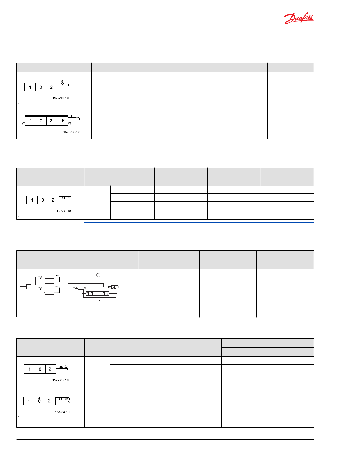
+
-
Setpoint
Driver A
Current
Feedback A
Driver B
Current
Feedback B
+
---
Technical Information
PVG 100 Proportional Valve Group
Modules and code numbers
Symbol Description Code Number
PVMR*, Cover for friction detent 157B0015
PVMF*, Mechanical float position lock, P -> A -> F 157B0005
*
Opposite of PVM, not compatible with PVG 100 PVBZ.
PVEO, ON/OFF Actuation
Symbol Description Hirschmann AMP Deutsch
12 V 24 V 12 V 24 V 12 V 24 V
PVEO ON/OFF 157B4216 157B4228 157B4901 157B4902 157B4291 157B4292
ON/OFF with ramp 157B4217 157B4229 157B4903 157B4904 11109080 11109092
ON/OFF anodized 157B4266 157B4268 - 157B4272 - -
®
Refer to catalog BC152886484010 for more PVE information.
PVHC - main spool control
Symbol Description AMP Deutsch
12 V 24 V 12 V 24 V
PVHC
11112037 11112036 11112038 11112039
The PVHC is an electrical
actuator module for main
spool control in PVG 32 and
PVG 100. The actuator uses
two current controlled
proportional pressure
reducing valves.
PVEA/PVEH/PVES, Proportional Actuation
Symbol Description Hirschmann AMP Deutsch
11 - 32 V 11 - 32 V 11 - 32 V
*
PVEA
PVEA-DI*Standard, active fault monitoring - 157B4736 157B4796
PVEH Standard, active fault monitoring 157B4032 157B4034 157B4092
PVEH-F Float, passive fault monitoring - 157B4075 157B4392
Standard, active fault monitoring - 157B4734 157B4792
Standard, passive fault monitoring - 157B4735 11107365
Standard, passive fault monitoring - 157B4737 -
Standard, passive fault monitoring 157B4033 157B4035 157B4093
Standard, passive, anodized 157B4073 - -
Float, active fault monitoring 157B4332 - -
®
44 | © Danfoss | April 2021 BC152886483475en-000606
Page 45

P
p
T0LSLS
comp
T P
PVLA
A
B
1 2
P301 134
Work Port Open To Tank
A
B
1 2
P301 135
T T0P LS LScompP
P
Technical Information
PVG 100 Proportional Valve Group
Modules and code numbers
Symbol Description Hirschmann AMP Deutsch
11 - 32 V 11 - 32 V 11 - 32 V
PVEH-DI Standard, active fault monitoring - 157B4036 157B4096
Standard, passive fault monitoring - 157B4037 -
PVES 0% hysteresis, active fault monitoring 157B4832 157B4834 157B4892
0% hysteresis, passive fault monitoring 157B4833 157B4835 11089276
PVEP PVEP, voltage PWM, active fault monitoring - - 11034832
PVED CAN bus interface - 11079034 11079033
*
PVEA with flows over 130 l/min [34.3 US gal/min] may not shift spool to full stroke
Refer to catalog BC152886484010 for more PVE information.
PVLA, Anti-Cavitation Valve Fitted into PVB
Symbol Description Code number
PVLA
Anti-cavitation valve installed
in PVLP cavity of PVB
157B2001
®
Cap
For connecting non-active work
port to tank
157B2002
©
Danfoss | April 2021 BC152886483475en-000606 | 45
Page 46

PVLP
1 2
P301 133
T
T0
A
B
P LSLScompP
P
Technical Information
PVG 100 Proportional Valve Group
Modules and code numbers
PVLP, Shock / Anti-Cavitation Valve Fitted into PVB
Symbol Description Setting Code number
bar psi
PVLP
Shock and anticavitation valve
(Not adjustable)
32 460 157B2032
50 725 157B2050
63 914 157B2063
80 1160 157B2080
100 1450 157B2100
125 1813 157B2125
140 2031 157B2140
150 2175 157B2150
160 2320 157B2160
175 2538 157B2175
190 2755 157B2190
210 3045 157B2210
230 3335 157B2230
240 3480 157B2240
250 3625 157B2250
265 3843 157B2265
280 4061 157B2280
300 4351 157B2300
320 4641 157B2320
350 5075 157B2350
PVT 100, Tank Module
Symbol Description Port size Code number
PVT
Without active elements
With T-port
PVLP shock valve facility
PVT
Without active elements
With T-port
PVLP shock valve facility
With LX connection G1/4
[ 9/16 in – 18 UNF]
G 1¼ 161B2500
15∕8-UNF 161B2520
G 1¼ 161B2505
15∕8-UNF 161B2525
46 | © Danfoss | April 2021 BC152886483475en-000606
Page 47

Technical Information
PVG 100 Proportional Valve Group
Modules and code numbers
PVTI 100/32, Interface Module*
Symbol Description Port size Code number
PVTI
Without active elements
With T-port
PVLP shock valve facility
* Must use T0 equipped PVG32 Modules, for details see Danfoss Technical Information Basis Modules
PVBZ, BC152886484167.
PVG 100 PVSI / PVT, Assembly Kit
Description Code number 161B….
1 PVB 2 PVB 3 PVB 4 PVB 5 PVB 6 PVB 7 PVB 8 PVB
Tie bolts and seals 8001 8002 8003 8004 8005 8006 8007 8008
G 1¼ 161B2200
15∕8-UNF 161B2220
PVBE (End Bodies), Assembly Kit
Description Code number
1 PVB 2 PVB 3 PVB 4 PVB 5 PVB 6 PVB 7 PVB 8 PVB
Tie bolts and seals 11081671 11017005 11017006 11017007 11017008 11017009 11017010 11017011
PVG 100 / PVTI, Interface Module Assembly Kit
Description Code number
0 PVB 1 PVB 2 PVB 3 PVB 4 PVB 5 PVB 6 PVB 7 PVB 8 PVB
Tie bolts and seals 11143008 161B8021 161B8022 161B8023 161B8024 161B8025 161B8026 161B8027 161B8028
PVB 32, Assembly Kit
Description Code number 157B….
1 PVB 2 PVB 3 PVB 4 PVB 5 PVB 6 PVB 7 PVB 8 PVB 9 PVB 10 PVB
Tie bolts and seals 8000 8001 8002 8003 8004 8005 8006 8007 8008 8009
©
Danfoss | April 2021 BC152886483475en-000606 | 47
Page 48

157-586.13
T P LS
A
B
T0P
p
Technical Information
PVG 100 Proportional Valve Group
Modules and code numbers
PVG 32 Basic Modules with T0, PVBZ (Compatible with PVG 100)
Symbol Description PVBZ Without thermal
Without compensator and load drop
check valve
With pilot operated check valves on
work port B
Max. work port pressure =
210 bar [3045 psi]
Without compensator and load drop
check valve
With pilot operated check valves on
work port A and B
Max. work port pressure =
210 bar [3045 psi]
With compensator
With pilot operated check valves on
work port B
Compensated work port flow A/B =
100 l/min [26.4 US gal/min]
Max. work port pressure =
210 bar [3045 psi]
relief valve 157B...
BSP SAE BSP SAE
6051 6451 - -
6052 6452 - -
6251 - 6261 6661
With thermal relief
valve 157B...
With compensator
With pilot operated check valves on
work port A and B
Compensated work port flow
A/B = 100 l/min [26.4 US gal/min]
Max. work port pressure 210 bar
[3045 psi]
With compensator
With pilot operated check valves on
work port A and B
LSA/B shuttle valve for float and
shuttle pin
Compensated work port flow
A/B = 100 l/min [26.4 US gal/min]
Max. work port pressure 210 bar
[3045 psi]
6252 6652 6262 6662
- - 6266 6666
48 | © Danfoss | April 2021 BC152886483475en-000606
Page 49

Technical Information
PVG 100 Proportional Valve Group
Modules and code numbers
Connection: A and B-port G 1/2 [ 7/8 in - 14]
Please refer to Publications BC152886483664 for PVBZ spool selection and to BC152886484167 for the
PVBZ modules with P.O. check.
PVG 32 Basic Modules with T0, PVB (Compatible with PVG 100)
Symbol Description PVB Code number 157B.....
Without PVLP 63 With PVLP 63
BSP SAE BSP SAE
Without load drop check valve and
pressure compensator.
Can be used where load holding
valves prevent oil from flowing back
through the channel P.
6010 6410 - -
Load drop check valve 6110 6909 6140 6904
With compensator valve 6210 6922 6240 6906
With compensator valve
Adjustable LS A/B limiting valves.
External LS connection port A/B.
Also used for float position spools.
6213 6613 6243 6643
Connection: A and B-port G 1/2 [7/8 in –14]
Refer to Publication BC152886483664 for PVB spool selection.
©
Danfoss | April 2021 BC152886483475en-000606 | 49
Page 50

Technical Information
PVG 100 Proportional Valve Group
Modules and code numbers
Standard Spools for Electrical and Mechanical Actuation Progressive Flow Characteristics
Symbol Pressure Compensated Flow (Specified flow is at 15 bar pump margin pressure)
4-way, 3 position, Closed Neutral Position 161B7022 161B7023 161B7024 161B7025 161B7026 161B7027
Standard Mount
Option Mount 11013079 11013080 11013081 11013082 11013083 11013084
4-way, 3-position, Throttled Open Neutral Position 161B7122 161B7123 161B7124 161B7125 161B7126 161B7127
Standard Mount
Option Mount 11013085 11013086 11013087 11013088 11013089 11013090
4-way, 4-position, Closed Neutral Position, Electric float
P –> A –> F
Standard Mount
Option Mount 11013091 11013092 11013093 11013094 11013095 11013096
4-way, 4-position, Throttled Open Neutral Position
Electric Float P –> A –> F
Standard Mount
l/min [US gal/min]
A
40 [10.6]
161B7622 161B7623 161B7624 161B7625 161B7626 161B7627
11016865 11016866 11016867 11016868 11016869 11016870
B
65 [17.2]
C
100 [26.4]D130 [34.4]E150 [39.6]F180 [47.6]
Option Mount 11016871 11016872 11016873 11016874 11016875 11016876
Standard Spools for Hydraulic Actuation Progressive Flow Characteristics
Symbol Pressure compensated Flow (Specified flow is at 15 bar pump margin pressure)
4-way, 3 position, Closed Neutral Position 161B9522 161B9523 161B9524 161B9525 161B9526 161B9527
Standard Mount
Option Mount 11013097 11013098 11013099 11013100 11013101 11013102
4-way, 3-position, Throttled Open Neutral Position 161B9622 161B9623 161B9624 161B9625 161B9626 161B9627
Standard Mount
Option Mount 11013103 11013104 11013105 11013106 11013107 11013108
l/min [US gal/min]
A
40 [10.6]
B
65 [17.2]
C
100 [26.4]D130 [34.4]E150 [39.6]F180 [47.6]
50 | © Danfoss | April 2021 BC152886483475en-000606
Page 51

Technical Information
PVG 100 Proportional Valve Group
Modules and code numbers
Symbol Pressure compensated Flow (Specified flow is at 15 bar pump margin pressure)
4-way, 4-position, Closed Neutral Position, Hydraulic
Float P -> A -> F
Standard Mount
Option Mount 11134635 11134636 11134637 11134638 11134639 11134692
l/min [US gal/min]
A
40 [10.6]
11134629 11134630 11134631 11134632 11134633 11134634
B
65 [17.2]
C
100 [26.4]D130 [34.4]E150 [39.6]F180 [47.6]
Spools for Friction Detent, PVMR (not compatible with PVBZ 100) Progressive Flow Characteristics
Symbol Pressure Compensated Flow (Specified flow is at 15 bar pump margin pressure)
l/min [US gal/min]
A
40 [10.6]
4-way, 3-position, Throttled Open Neutral Position 161B9732 161B9733 161B9734 161B9735 161B9736 161B9737
Standard Mount
Option Mount 11013109 11013110 11013111 11013112 11013113 11013114
B
65 [17.2]
C
100 [26.4]D130 [34.4]E150 [39.6]F180 [47.6]
Spools for Mechanical Float position, PVMF (not compatible with PVBZ 100) Progressive Flow Characteristics
Symbol Pressure Compensated Flow (Specified flow is at 15 bar pump margin pressure)
4-way, 4 position, Closed Neutral Position 161B9822 161B9823 161B9824 161B9825 161B9826 161B9827
Standard Mount
Option Mount 11013115 11013116 11013117 11013118 11013119 11013120
l/min [US gal/min]
A
40 [10.6]
B
65 [17.2]
C
100 [26.4]D130 [34.4]E150 [39.6]F180 [47.6]
Standard Spools (Electrical and Mechanical Actuation) Linear Flow Characteristics
Symbol Pressure Compensated Flow (Specified flow is at 15 bar pump margin pressure)
l/min [US gal/min]
A
40 [10.6]
4-way, 3 position, Closed Neutral Position 11016852 11016853 11016854 11016855 11016857 11016858
Standard Mount
Option Mount 11016859 11016860 11016861 11016862 11016863 11016864
B
65 [17.2]
C
100 [26.4]D130 [34.4]E150 [39.6]F180 [47.6]
©
Danfoss | April 2021 BC152886483475en-000606 | 51
Page 52

Technical Information
PVG 100 Proportional Valve Group
Modules and code numbers
Standard Spools (Electrical and Mechanical Actuation) Throttled Open in Neutral, Linear Flow Characteristics
Symbol Pressure Compensated Flow (Specified flow is at 15 bar pump margin pressure)
l/min [US gal/min]
A
40 [10.6]
4-way, 3-position, Throttled Open Neutral Position 11116606 11116607 11116608 11116609 11116610 11116611
Standard Mount
Option Mount - - 11090529 11090653 - -
Standard Spools (Hydraulic and Mechanical Actuation), Throttled Open in Neutral, Linear Flow Characteristics
Symbol Pressure Compensated Flow (Specified flow is at 15 bar pump margin pressure)
l/min [US gal/min]
A
40 [10.6]
4-way, 3 position, Throttled Open, Neutral Position 11116612 11116613 11116614 11116615 11116616 11116617
Standard Mount
B
65 [17.2]
B
65 [17.2]
C
100 [26.4]D130 [34.4]E150 [39.6]F180 [47.6]
C
100 [26.4]D130 [34.4]E150 [39.6]F180 [47.6]
Standard Spools (Electrical and Mechanical Actuation), Full Open in Neutral; Progressive Flow Characteristics
Symbol Pressure Compensated Flow (Specified flow is at 15 bar pump margin pressure)
4-way, 3 position, Full Open, Neutral Position 11121597 11121598 11121599 11121600 11121601 11145837
Standard Mount
l/min [US gal/min]
A
40 [10.6]
B
65 [17.2]
C
100 [26.4]D130 [34.4]E150 [39.6]F180 [47.6]
Standard Spools (Hydraulic and Mechanical Actuation), Full Open in neutral; Linear Flow Characteristics
Symbol Pressure Compensated Flow (Specified flow is at 15 bar pump margin pressure)
l/min [US gal/min]
A
40 [10.6]
4-way, 3 position, Full Open, Neutral Position 11121602 11121603 11121604 11121605 11121606 11005747
Standard Mount
B
65 [17.2]
C
100 [26.4]D130 [34.4]E150 [39.6]F180 [47.6]
52 | © Danfoss | April 2021 BC152886483475en-000606
Page 53

Technical Information
PVG 100 Proportional Valve Group
Modules and code numbers
High Flow Spools (Electrical and Mechanical Actuation) Progressive Flow Characteristics
High Flow Spools (Electrical and Mechanical Actuation)
Symbol Pressure Compensated Flow
(Specified flow is at 15 bar pump margin pressure)
210 l/min
[55.4 US gal/min]
4-way, 3 position, Closed Neutral Position 11102188 11102192
Standard Mount
Option Mount 11102200 11102205
4-way, 3-position, Throttled Open Neutral Position 11102189 11102193
Standard Mount
Option Mount 11102201 11102206
240 l/min
[63.4 US gal/min]
High Flow Spools (Hydraulic and Mechanical Actuation) Progressive Flow Characteristics
High Flow Spools (Hydraulic and Mechanical Actuation)
Symbol Pressure Compensated Flow
(Specified flow is at 15 bar pump margin pressure)
210 l/min
[55.4 US gal/min]
4-way, 3 position, Closed Neutral Position 11102186 11102190
Standard Mount
Option Mount 11102198 11102202
4-way, 3-position, Throttled Open Neutral Position 11102187 11102191
Standard Mount
Option Mount 11102199 11102203
240 l/min
[63.4 US gal/min]
©
Danfoss | April 2021 BC152886483475en-000606 | 53
Page 54

PVB part number
includes seal plate
P301 136
020065
4-Way, 3-Position, Closed Neutral Position
Standard Mount
P301 138
4-Way, 3-Position, Throttled Open
Standard Mount
P301 139
Technical Information
PVG 100 Proportional Valve Group
Modules and code numbers
High Flow Spools, Full Open A/B → T and Neutral; Progressive Flow Characteristics
High Flow Spools (Hydraulic and Mechanical Actuation)
Symbol Pressure Compensated Flow
4-way, 3 position, Closed Neutral Position, Electrical Actuation 11148962 11148961
Standard Mount
Option Mount 11148951 11148952
4-way, 3 position, Closed Neutral Position, Hydraulic Actuation 11148953 11148954
Standard Mount
Option Mount 11148955 11148956
(Specified flow is at 15 bar pump margin pressure)
210 l/min
[55.4 US gal/min]
240 l/min
[63.4 US gal/min]
Exposed spools Progressive Flow Characteristics
The following spools are available with an exposed tang for mechanical actuation. These spools are only
available for standard mounting.
Symbol Pressure compensated flow l/min [US gal/min]*
A
40 [10.6]
11051695 11051696 11051697 11051698 11051699 11051700
B
65 [17.2]
C
100 [26.4]
D
130 [34.4]
E
150 [39.6]
F
180 [47.6]
11051701 11051702 11051703 11051704 11051705 11051706
54 | © Danfoss | April 2021 BC152886483475en-000606
Page 55

P301 064
Technical Information
PVG 100 Proportional Valve Group
Dimensions
PVG 100 dimensions in general
©
Danfoss | April 2021 BC152886483475en-000606 | 55
Page 56

Technical Information
PVG 100 Proportional Valve Group
Dimensions
PVG 100 with open center PVPF dimensions
Pp accumulator: G¼ [9∕16 in-18UNF] P: Pump port: G1 [15∕16 in-12UNF]
T0 and LS: G¼ [9∕16 in-18UNF] L: LS relief valve
P and Pp gauge: G¼ [9∕16 in-18UNF] G: PVPE unloading valve
K: LX: G¼ [9∕16 in-18UNF] H: PVPP pilot shut off valve
F: Tank port: G1 [15∕16 in-12UNF] J: Mounting thread; M12 x 14 mm deep
To avoid spool bind or leakage between sections caused by uneven mounting surfaces it is
recommended to only use 3 of 4 mounting holes provided.
1 PVB 2 PVB 3 PVB 4 PVB 5 PVB 6 PVB 7 PVB 8 PVB
L1 mm 80 128 176 224 272 320 368 416
[in] [3.15] [5.04] [6.93] [8.82] [10.71] [12.60] [14.49] [16.38]
56 | © Danfoss | April 2021 BC152886483475en-000606
Page 57

Technical Information
PVG 100 Proportional Valve Group
Dimensions
1 PVB 2 PVB 3 PVB 4 PVB 5 PVB 6 PVB 7 PVB 8 PVB
L2 mm 176 224 272 320 368 416 464 512
[in] [6.93] [8.82] [10.71] [12.60] [14.49] [16.38] [18.27] [20.16]
PVG 100/32, closed center PVPV
Pp accumulator: G¼ [9∕16 in-18UNF] E: Port A and B PVB 100; G¾ [11∕16 inin - 12 UNF]
©
Danfoss | April 2021 BC152886483475en-000606 | 57
Page 58

Technical Information
PVG 100 Proportional Valve Group
Dimensions
T0 and LS: G¼ [9∕16 in-18UNF] H : Port A and B PVB 32; G½ [7∕8 in - 14 UNF]
P and Pp gauge: G¼ [9∕16 in-18UNF] I : Mounting thread ; M8 x 15 mm deep [5∕16 in - 18 UNC]
D: Pump port; G1 [15∕16 in-12UNF] J: Mounting thread; M12 x 14 mm deep
F: Tank port; G1¼ [15∕8 in - 12 UNF] L: LS relief valve
1 PVB 2 PVB 3 PVB 4 PVB 5 PVB 6 PVB 7 PVB 8 PVB 9 PVB 10 PVB
L1 mm 80 128 176 224 272 320 368 416 - -
[in] [3.15] [5.04] [6.93] [8.82] [10.71] [12.60] [14.49] [16.38] - -
L2 mm 100 148 196 244 292 340 388 436 484 532
[in] [3.94] [5.83] [7.72] [9.61] [11.50] [13.39] [15.28] [17.16] [19.05] [20.94]
L3 mm - 245 293 341 389 437 485 533 581 629
[in] - [9.64] [11.54] [13.43] [15.31] [17.20] [19.09] [20.98] [22.87] [24.76]
It is recommended not to exceed 10 PVB 100/32 in a valve group.
PVG 100, Closed Center PVP with Integrated Priority Valve
CF: G½ [¾ in - 16 UNF] K: LX connection G¼ [9∕16 in - 18 UNF]
LS: G¼ [9∕16 in - 18 UNF] Lst: LS for steering unit; G¼ [9∕16 in - 18 UNF]
P gauge: G¼ [7∕16 in - 24 UNF] E: Port A and B PVB 100; G¾ [1 1∕16 in - 12 UNF]
Port A and B for High flow PVB G3/4 [1 3/1614 UNF]
58 | © Danfoss | April 2021 BC152886483475en-000606
Page 59

P301 140E
161 ± 3.0
[6.34 ± 0.12]
Inlet Ports
161 ± 3
[6.34 ± 0.12]
Tank Ports
111.5 ± 2.5
[4.39 ± 0.1]
LX Ports
(9/16-18 SAE)
3X Torque
38 - 42 N•m
131 ± 2.5
[5.16 ± 0.1]
To port
(9/16-18 SAE)
12 ± 2
[0.47 ± 0.08]
161 ± 3
[6.34 ± 0.12]
Work Ports
173 ± 3
[6.81 ± 0.12]
(83)
[3.27]
(44)
[1.73]
(60)
[2.36]
(247)
[9.72]
12.5 ± 2 [0.49 ± 0.08]
12.5 ± 2 [0.49 ± 0.08]
39 ± 2 [1.53 ± 0.08]
224 ± 2.5 [9.6 ± 0.1]
235 ± 3 [9.25 ± 0.12]
(268) [10.55]
135 ± 2.5 [5.31 ± 0.1]
183 ± 2.5 [7.2 ± 0.1]
201
REF.
175
REF.
Outlet ports
(1 5/8-12 SAE)
118.0 ± 2.5
[4.65 ± 0.1]
Inlet Port
(1 5/16-12 SAE)
93 ± 2
[3.66 ± 0.08]
62.5 ± 2
[2.46 ± 0.08]
(51.3) [2.02]
24.5 ± 2.0 [0.96 ± 0.08]
87 ± 2 [3.43 ± 0.08]
92.5
[3.64]
Technical Information
PVG 100 Proportional Valve Group
Dimensions
T0 port: G¼ [9∕16 in - 18 UNF] H: Mounting thread M12 x 14 mm deep
Pp gauge: G¼ [7∕16 in - 24 UNF] J: Mounting bracket with holes for M12 screws
P pump: G¾ [1 1∕16 in - 12 UNF] M: LS relief valve
F: G¼ [1 1∕16 in]
1 PVB 2 PVB 3 PVB 4 PVB 5 PVB 6 PVB 7 PVB 8 PVB
L1 mm 140 188 236 284 332 380 428 476
[in] [5.51] [5.12] [9.29] [11.18] [9.13] [14.96] [16.85] [18.74]
L2 mm 198 246 294 342 390 438 486 534
[in] [7.80] [9.69] [11.57] [13.46] [15.35] [17.24] [19.13] [21.02]
Examples
PVG 100 with variable displ. pump
©
Danfoss | April 2021 BC152886483475en-000606 | 59
Page 60

P301 791
176.0 [6.93]
231.0 [9.09]
407.0 [16.02]
118.0 [4.65]
85.0 [3.35]
Technical Information
PVG 100 Proportional Valve Group
Dimensions
PVPVM with two PVT modules
60 | © Danfoss | April 2021 BC152886483475en-000606
Page 61

185.0 [7.28]
240.0 [9.45]
416.0 [16.38]
118.0 [4.65]
81.0 [3.19]
474.0 [18.66]
40.0 [1.57] 85.0 [3.35]
Technical Information
PVG 100 Proportional Valve Group
Dimensions
PVPVM with one PVT and one PVBE
©
Danfoss | April 2021 BC152886483475en-000606 | 61
Page 62
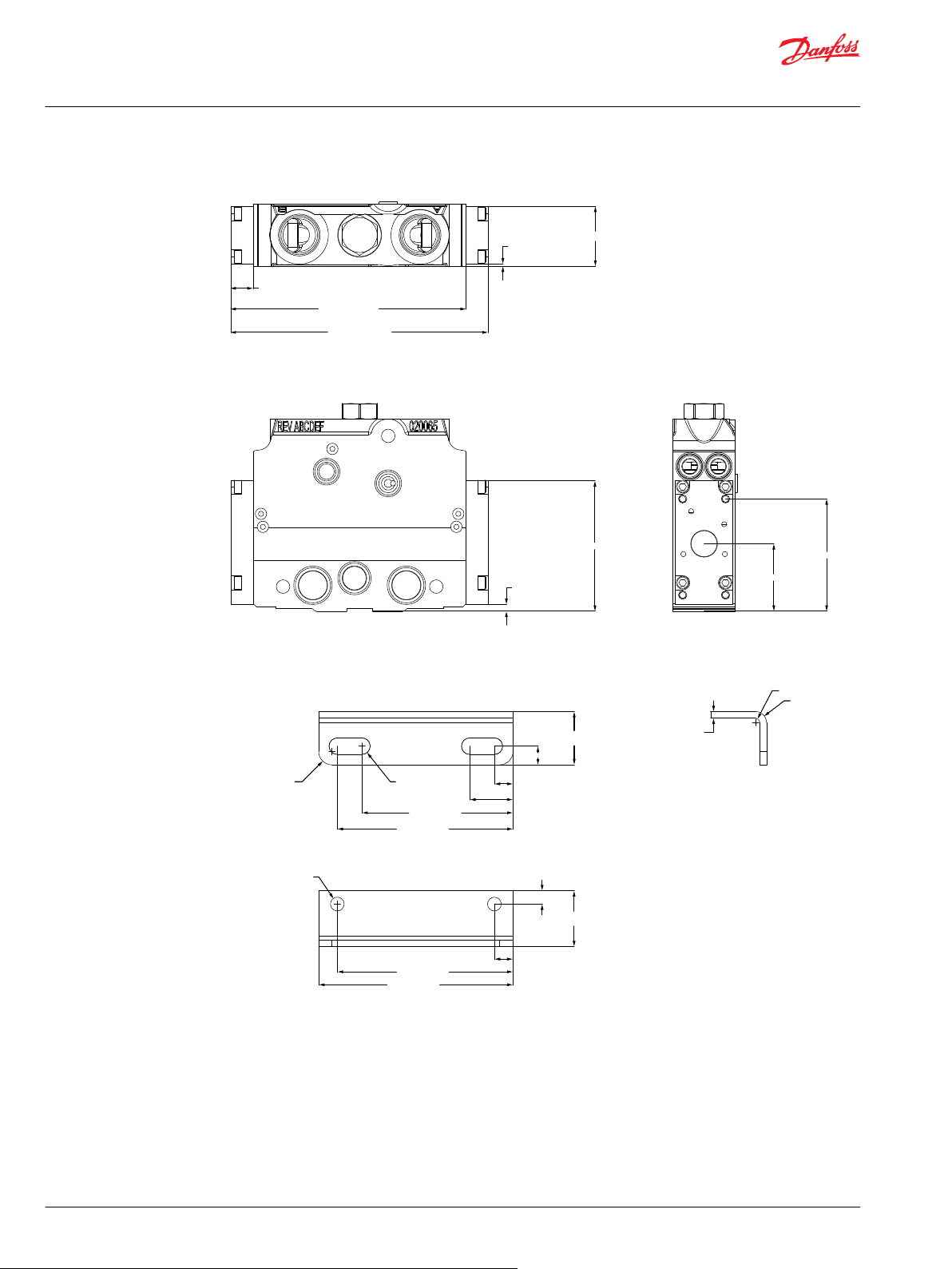
198.0 [7.80]
181.0 [7.13]
17.0 [0.67]
100.5 [3.96]
5.3 [0.21]
46.2 [1.82]
1.8 [0.07]
86.5 [3.41]
52.0 [2.05]
P301 793
182.5 [7.19]
∅12.9 [∅0.51]x2
R7.8 [R0.31]x4R12.5 [R0.49]x2
52.5 [2.07]
12.5 [0.49]
165.0 [6.50]
17.5 [0.69]
17.5 [0.69]
50.0 [1.97]
17.5 [0.69]
40.6 [1.60]
141.9 [5.59]
165.0 [6.50]
6.3 [0.25]
R4.0 [R0.16]
R10.2 [R0.40]
P301 794
Technical Information
PVG 100 Proportional Valve Group
Dimensions
High Flow PVB module
PVBE mounting bracket
62 | © Danfoss | April 2021 BC152886483475en-000606
Page 63
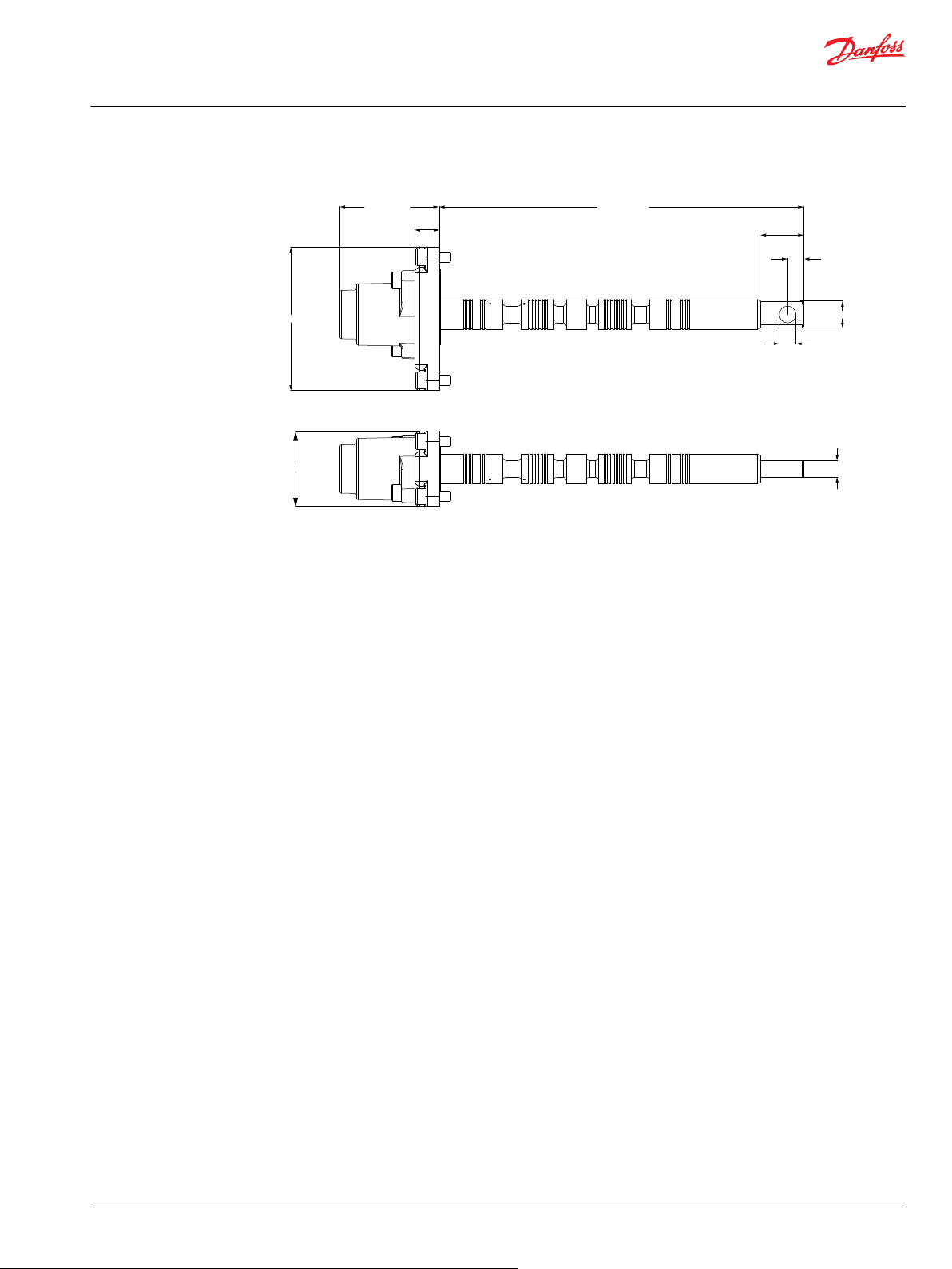
45.0 [1.77]
59.8 [2.36]
14.8 [0.58]
218.9 [8.62]
9.9 [0.39]
26.2 [1.03]
9.7 [0.38]
16.0 [0.63]
86.0 [3.39]
10.0 [0.40]
P301 795
Technical Information
PVG 100 Proportional Valve Group
Dimensions
PVBSO module
©
Danfoss | April 2021 BC152886483475en-000606 | 63
Page 64

157-699.11
0 0 0
1-12
13
15
16
a
b
c
c
PVPP
PVP
PVB
PVTI
PVT
PVM
PVLP/A
Assembly kit
PVBZ
PVPC
PVE, PVHC
PVMD, PVH
PVPE
PVPD
Technical Information
PVG 100 Proportional Valve Group
Module selection chart
Exploded view for module selection
PVP 100, Pump Side Module – Open center, PVPF with pilot supply (excludes PVPD/PVPE)
Port (includes
pilot gauge
port)
P = G 1 161B5110 161B5112 161B5140 161B5142 11013065 11013067 11013071 11013073
P = 15/16 UNF 161B5510 161B5512 161B5540 161B5542 11013066 11013068 11013072 11013074
Weight 8.5 kg [12.3 lb]
Open center, PVPF with pilot supply
for PVE for PVE and facility for pilot
12 bar 20 bar 12 bar 20 bar 12 bar 20 bar 12 bar 20 bar
shut off
for PVH/PVHC for PVH/PVHC and facility for
pilot shut off
PVP 100, Pump Side Module – Closed center, PVPV with pilot supply
Port (includes pilot
gauge port)
P = G 1 161B5111 161B5141 - 11013069 11013075 P = 1⁵⁄₁₆ UNF 161B5511 161B5541 - 11013070 11013076 -
Closed center, PVPV with pilot supply
for PVE for PVE and facility
for pilot shut-off
for PVE with
integrated priority
function
for PVH/PVHC for PVH/PVHC and
facility for pilot
shut-off
for PVH/PVHC with
integrated priority
function
64 | © Danfoss | April 2021 BC152886483475en-000606
Page 65
Technical Information
PVG 100 Proportional Valve Group
Module selection chart
PVP 100, Pump Side Module – Closed center, PVPV with pilot supply (continued)
Port (includes pilot
gauge port)
P = G ¾; T = G 1 - - 161B5211 - - 11013077
P = G 1 1/16 UNF; T
= 1⁵⁄₁₆ UNF
Weight 8.5 kg [12.3 lb]
PVP 100, Pump Side Module – Mid Inlet, PVPVM with pilot supply
Port Closed center, PVPVM with pilot supply
P = 1 ¼ in Metric flange BSP 11130086 11133046
P = 1 ¼ in Metric flange SAE 11133048 11133047
PVB, Basic Module
Code no. Without facilities for shock valves A and B With facilities for shock valves A and B
Without pilot operated check valve 161B6250 161B6650 161B6260 161B6660
With pilot operated check valve 161B6252 161B6652 161B6262 161B6662
Open spools PVB 11051707 11051708 11051709 11051710
Open spools PVBZ 11051711 11051712 11051713 11051714
End module - 11036948 11006889 11070866
Module with tank port in bottom - - 11006887 PVB module, twin shock valve - - - 11077581
Weight kg [lb] 5.5 kg [12.13 lb]
Closed center, PVPV with pilot supply
for PVE for PVE and facility
for pilot shut-off
- - 161B5611 - - 11013078
G ¾ 1 1/16-12 UNF G ¾ 1 1/16-12 UNF
for PVE with
integrated priority
function
for PVE for PVH/PVHC
for PVH/PVHC for PVH/PVHC and
facility for pilot
shut-off
for PVH/PVHC with
integrated priority
function
PVB, Basic Module – High Flow 20 mm
Code no. Without facilities for shock valves A and B With facilities for shock valves A and B
G ¾ 1 3/16-12 UNF G ¾ 1 3/16-12 UNF
Without pilot operated check valve 11102180 11102181 11102178 11101825
With pilot operated check valve 11102184 11102185 11102182 11102183
PVP, Accessory Module for PVP 100
Code no. Weight
Plug, PVPD 155G5041
*
For PVPF only
*
0.4 kg [0.9 lb]
PVPE, Accessory Module for PVP 100
Code no. 12 V 24 V Weight
PVPE, Elec. unloading valve 155G5052
PVPH, hydraulic unloading valve 155G5061
*
For PVPF only
©
Danfoss | April 2021 BC152886483475en-000606 | 65
*
155G5054** 0.7 kg [1.1 lb]
Page 66

Technical Information
PVG 100 Proportional Valve Group
Module selection chart
PVPC, External pilot supply
Code no. G¼ 7/16-20 UNF 1/2-20 UNF Weight
Without check valve 157B5400 158X1000 - 0.05 kg
With check valve 157B5600 - 157B5700
Not available for PVPV 157B5211 and 157B5611, (for details see catalog, BC152886483664)
PVM, mechanical actuation
Code No. With
Standard 157B3171
Standard, with base,
without arm and button
Standard, without base,
arm and button
Weight kg [lb] 0.4 [0.9]
*
Anodized 157B3184
**
Cast iron
stop screw
157B3161
157B3174
157B3175
157B3173
157B3172
*
**
Without
stop screw
157B3191 22.5°
157B3194
157B3192
157B3193
157B3195
[0.1 lb]
Lever position angle
37.5°
–
–
PVB, PVBZ Spools
Code no. Without facilities for
shock valves A and B
G ¾ 1 1/16-12 G ¾ 1 1/16-12
Open spools PVB 11051707 11051708 11051709 11051710
Open spools PVBZ 11051711 11051712 11051713 11051714
With facilities for
shock valves A and B
PVLA, Anti-Cavitation Valve
PVLA Code No. Weight
Cap A or B 157B2002 0.04 kg [0.09 lb]
Valve A or B 157B2001 0.05 kg [0.1 lb]
PVLP, shock/and anti-cavitation valves
Code no. 157B.… 2032 2050 2063 2080 2100 2125 2140 2150 2160 2175
Setting bar 32 50 63 80 100 125 140 150 160 175
[psi] [460] [725] [914] [1160] [1450] [1813] [2031] [2175] [2320] [2538]
Weight kg [lb] 0.05 kg [17 lb]
PVLP, shock/and anti-cavitation valves
Code no. 157B.… 2190 2210 2230 2240 2250 2265 2280 2300 2320 2350
Setting bar 190 210 230 240 250 265 280 300 320 350
[psi] [2755] [3045] [3335] [3480] [3625] [3845] [4061] [4351] [4641] [5075]
Weight kg [lb] 0.05 kg [17 lb]
66 | © Danfoss | April 2021 BC152886483475en-000606
Page 67

Technical Information
PVG 100 Proportional Valve Group
Module selection chart
Accessory Module for PVP 100
Code no. 12 V 24 V Weight
PVPP, Pilot shut off valve 11160318 11160319 0.3 kg [0.7 lb]
PVE, Electrical Actuation
Code No. Hirsch AMP DEUTSCH Weight
PVEO, ON/OFF 12 V
PVEO, ON/OFF Anodised 12 V
PVEO-R, ON/OFF 12 V
PVEA, active fault mon.
PVEA, passive fault mon.
PVEA-DI, active fault mon.
PVEA-DI, passive fault mon.
PVEH active fault mon.
PVEH passive fault mon.
PVEH passive fault mon. (anodized)
PVEH-F float pos. 157B4332 - 157B4392
PVEH-DI active fault mon.
PVEH-DI passive fault mon.
PVEP active fault mon. - - 11034832
PVES, active fault mon.
PVES, passive fault mon.
PVED-CC, Can-Bus interface - 11079034 11079033
*
PVEA with flows over 130 l/min [34.3 US gal/min] may not shift spool to full stroke
*
*
24 V
24 V
24 V
157B4216
157B4228
157B4266
157B4268
157B4217
157B4229
-
-
-
157B4032
157B4033
157B4073
-
-
157B4832
157B4833
157B4901
157B4902
157B4272
157B4903
157B4904
157B4734
157B4735
157B4736
157B4737
157B4034
157B4035
157B4075
157B4036
157B4037
157B4834
157B4835
157B4291
157B4292
-
11109080
11109092
157B4792
11107365
157B4796
157B4092
157B4093
157B4096
-
157B4892
11089276
0.6 kg
[1.3 lb]
0.9 kg
[2 lb]
1 kg
[2.2 lb]
Refer to catalog BC152886484010 for more PVE information
PVHC, High Current PWM Actuator
Code No. 12 V 24 V
Amp 11112037 11112036
Deutsch 11112038 11112039
PVMD, PVH, PVMR, PVMF Covers
Code No. Weight
Cover for PVM 157B0001 0.1 kg [0.2 lb]
Cover for Hydraulic Remote Control 157B0021
PVH, Hydraulic actuation G 1/4 157B0008 0.2 kg [0.4 lb]
9/16 -18 UNF 157B0007 0.9 kg [2.0 lb]
PVMR (friction detent) 157B0015 0.3 kg [0.6 lb]
PVMF (mech. float position) 157B0005
PVTI 100/32 interface module
Code no. BSP SAE Weight
PVTI, with T-port and PVLP facility 161B2200 161B2220 8.7 kg [19.18 lb]
T-connection G 1¼ [15∕8 UNF]
©
Danfoss | April 2021 BC152886483475en-000606 | 67
Page 68

Technical Information
PVG 100 Proportional Valve Group
Module selection chart
Tank Module, PVT
Code no. BSP SAE Weight
PVT, with T-port and PVLP facility 161B2500 161B2520 6.3 kg [13.89 lb]
PVT, with LX connection, T-port and PVLP facility 161B2505 161B2525
T-connection G 1¼ [15∕8 UNF]
Assembly Kit PVG 100 / PVT
Description Code No.
1 PVB 2 PVB 3 PVB 4 PVB 5 PVB 6 PVB 7 PVB 8 PVB
Tie bolts and seals 161B8001 161B8002 161B8003 161B8004 161B8005 161B8006 161B8007 161B8008
Assembly Kit PVG 100 / PVTI Interface Module
Description Code No.
0 PVB 1 PVB 2 PVB 3 PVB 4 PVB 5 PVB 6 PVB 7 PVB 8 PVB
Tie bolts and seals 11143008 161B8021 161B8022 161B8023 161B8024 161B8025 161B8026 161B8027 161B8028
Assembly Kit PVG100 for PVB End module (must be used with bottom tank ported PVB)
Description Code No.
1 PVB 2 PVB 3 PVB 4 PVB 5 PVB 6 PVB 7 PVB 8 PVB
Tie bolts and seals 11081671 11017005 11017006 11017007 11017008 11017009 11017010 11017011
Assembly Kit PVB 32
Description Code No.
1 PVB 2 PVB 3 PVB 4 PVB 5 PVB 6 PVB 7 PVB 8 PVB 9 PVB 10 PVB
PVB’s 157B8000 157B8001 157B8002 157B8003 157B8004 157B8005 157B8006 157B8007 157B8008 157B8009
Weight [kg [lb] 0.1 [0.2] 0.15 [0.3] 0.25 [0.6] 0.3 [0.7] 0.4 [0.9] 0.45 [1] 0.5 [1.1] 0.6 [1.3] 0.65 [1.4] 0.7 [1.6]
68 | © Danfoss | April 2021 BC152886483475en-000606
Page 69

Technical Information
PVG 100 Proportional Valve Group
PVG 100 order specification
The PVG 100 Inlet LS relief valve (1) is specifically designed to ensure a constant margin pressure across
the main spool, providing demanded regulated flow during maximum load pressure conditions. This
relief adjustment is critical when there are two or more functions being operated together. An incorrectly
adjusted Inlet relief could result in a vast reduction in regulated flow from the adjacent functions that
operate at a lower load pressure. To accurately adjust the inlet LS relief, the pump standby pressure must
be known in addition to the maximum operating load pressure.
Example
Pressure comp pressure level 172 bar [2500 psi]
LS standby pressure requirement that delivers the desired flow -20 bar [-290 psi]
Maximum load pressure requirement 152 bar [2210 psi]
Inlet relief pressure setting 152 bar [2210 psi]
An order form for Danfoss PVG 100 hydraulic valve is shown on the next page. The form can be obtained
from the Danfoss Sales Organization.
Both the module selection chart on the previous pages and the order form are divided into fields 0, 1-10,
11, 12, 13, a, b, and c.
Each module has its own field:
0: Pump side module PVP
• Plug for external pilot oil supply PVPC
• Electrical unloading valve PVPE
• Electrical pilot shut off valve PVPE
1-10: Basic valves PVB
13: Main spool PVBS
a: Mechanical actuator PVM
c: Cover for mechanical actuation PVMD
Cover for hydraulic actuation PVH
Electrical actuators PVE
b: Shock and suction valve PVLP
Suction valve PVLA
11: End plate PVSI
Tank module PVT
Interface module PVTI
12: Assembly kit PVAS
Please state
Code numbers of all modules required
•
Required setting (P) for pump side module
•
Standard and option assembly
The valve group is assembled the way the module selection chart shows if the code number for PVM is
written in field 'a', and the code number for PVMD, PVE or PVH in field 'c'.
©
Danfoss | April 2021 BC152886483475en-000606 | 69
Page 70

Technical Information
PVG 100 Proportional Valve Group
PVG 100 order specification
The valve group is assembled so that the mechanical actuator is mounted on the opposite end of the
basic module, if the code number for PVM is written in field 'c' of the order form and the code numbers
for PVMD, PVE or PVH in field 'a'.
Reordering
The space at the top right-hand corner of the form is for Danfoss to fill in. The code number for the whole
of the specified valve group (PVG No.) is entered here.
In the event of a repeat order all you have to do is enter the number Danfoss has given on the initial
confirmation of order.
70 | © Danfoss | April 2021 BC152886483475en-000606
Page 71

Technical Information
PVG 100 Proportional Valve Group
Specification sheet
Specification form
©
Danfoss | April 2021 BC152886483475en-000606 | 71
Page 72

PVG PN
Subsidiary / Dealer:
Customer:
Functio n
Mountin g Bracke t
p=
bar
PVAS PVBE
a
PVM
PVBE. SAE
SPOOL 180L STANDARD ELECTRICAL ACTUATION
PVEH.(G) Proportional. Active Fault Monitoring
a
b
b
b
LS
A
bar
LS
B
bar
b
a
PVM PVB
SPOOL 180L STANDARD ELECTRICAL ACTUATION
PVEH.(G) Proportional. Active Fault Monitoring
a
b
b
b
LS
A
bar
LS
B
bar
b
a
PVM PVB
SPOOL 180L STANDARD ELECTRICAL ACTUATION
PVEH.(G) Proportional. Active Fault Monitoring
a
b
b
b
LS
A
bar
LS
B
bar
b
a
PVPVM100 SAE PVE
a
b
b
b
LS
A
bar
LS
B
bar
b
a
PVM PVB PVBS
PVEH.(G) Proportional. Active Fault Monitoring
a
b
b
b
LS
A
bar
LS
B
bar
b
a
PVM PVB PVBS
PVEH.(G) Proportional. Active Fault Monitoring
a
b
b
b
LS
A
bar
LS
B
bar
b
a
PVM PVB PVBS
PVEH.(G) Proportional. Active Fault Monitoring
a
b
b
b
LS
A
bar
LS
B
bar
b
a
a
b
b
b
LS
A
bar
LS
B
bar
b
a
a
b
b
b
LS
A
bar
LS
B
bar
b
a
a
b
b
b
LS
A
bar
LS
B
bar
b
a
a
b
b
b
LS
A
bar
LS
B
bar
b
a
a
b
b
b
LS
A
bar
LS
B
bar
b
13
PVT PVLP
b
BUSINESS TYPE
14
EAU
15
PVAS
Filled in by:
Date:
A - Port
0
11144936
B- Port
11017006
PVG Specification
PVG100
X
Application:
157B4092
157B3171
1
11036948
11013084
16
157B3171
3
161B6650
11013084
157B3171
2
161B6650
11013084
16
157B4092
16
157B4092
4
11133048
16
157B4092
157B3171
5
161B6650
161B7027
16
157B4092
157B3171
6
161B6650
161B7027
16
157B4092
157B3171
7
161B6650
161B7027
16
8
16
9
16
10
16
11
16
12
16
161B2520
157B2300
161B8003
P301 799
Technical Information
PVG 100 Proportional Valve Group
Specification sheet
Specification example for PVPVM
72 | © Danfoss | April 2021 BC152886483475en-000606
Page 73

Danfoss
Power Solutions GmbH & Co. OHG
Krokamp 35
D-24539 Neumünster, Germany
Phone: +49 4321 871 0
Danfoss
Power Solutions ApS
Nordborgvej 81
DK-6430 Nordborg, Denmark
Phone: +45 7488 2222
Danfoss
Power Solutions (US) Company
2800 East 13th Street
Ames, IA 50010, USA
Phone: +1 515 239 6000
Danfoss
Power Solutions Trading
(Shanghai) Co., Ltd.
Building #22, No. 1000 Jin Hai Rd
Jin Qiao, Pudong New District
Shanghai, China 201206
Phone: +86 21 2080 6201
Products we offer:
Hydro-Gear
www.hydro-gear.com
Daikin-Sauer-Danfoss
www.daikin-sauer-danfoss.com
Cartridge valves
•
DCV directional control
•
valves
Electric converters
•
Electric machines
•
Electric motors
•
Gear motors
•
Gear pumps
•
Hydraulic integrated
•
circuits (HICs)
Hydrostatic motors
•
Hydrostatic pumps
•
Orbital motors
•
PLUS+1® controllers
•
PLUS+1® displays
•
PLUS+1® joysticks and
•
pedals
PLUS+1® operator
•
interfaces
PLUS+1® sensors
•
PLUS+1® software
•
PLUS+1® software services,
•
support and training
Position controls and
•
sensors
PVG proportional valves
•
Steering components and
•
systems
Telematics
•
Danfoss Power Solutions is a global manufacturer and supplier of high-quality hydraulic and
electric components. We specialize in providing state-of-the-art technology and solutions
that excel in the harsh operating conditions of the mobile off-highway market as well as the
marine sector. Building on our extensive applications expertise, we work closely with you to
ensure exceptional performance for a broad range of applications. We help you and other
customers around the world speed up system development, reduce costs and bring vehicles
and vessels to market faster.
Danfoss Power Solutions – your strongest partner in mobile hydraulics and mobile
electrification.
Go to www.danfoss.com for further product information.
We offer you expert worldwide support for ensuring the best possible solutions for
outstanding performance. And with an extensive network of Global Service Partners, we also
provide you with comprehensive global service for all of our components.
Local address:
Danfoss can accept no responsibility for possible errors in catalogues, brochures and other printed material. Danfoss reserves the right to alter its products without notice. This also applies to products
already on order provided that such alterations can be made without subsequent changes being necessary in specifications already agreed.
All trademarks in this material are property of the respective companies. Danfoss and the Danfoss logotype are trademarks of Danfoss A/S. All rights reserved.
©
Danfoss | April 2021 BC152886483475en-000606
 Loading...