

Page 1
Proportional Valves Technical Information
2
1
S2
S1
2
1
4
3
T
P
A
B
P
T
A
B
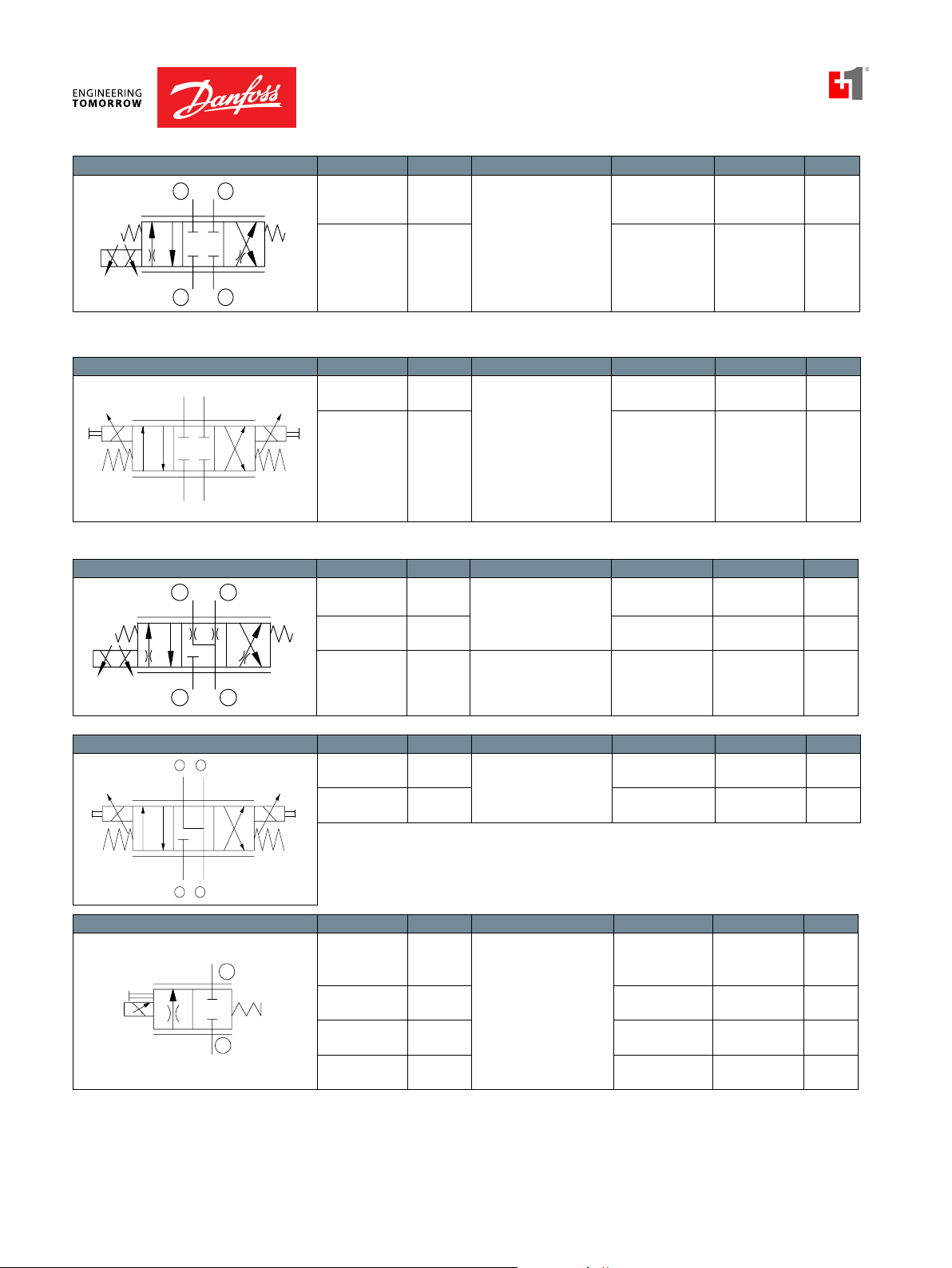
Quick Reference
Proportional Directional Model No. Cavity Description Flow* Pressure Page
PSV10-34-02 SDC10-4 Proportional Directional
Valve
22 l/min
[6 US gal/min]
250 bar
[3600 psi]
PV - 13
PSV12-34-02 CP12-4 50 l/min
[13 US gal/min]
250 bar
[3600 psi]
PV - 15
Proportional Directional Model No. Cavity Description Flow* Pressure Page
PDCV03-3Z11 ISO D03 Proportional Directional
Valve
PDCV05-3Z11 ISO D05 60 l/min
Quick Reference
Proportional Directional Model No. Cavity Description Flow* Pressure Page
2
4
PSV08-34-05 SDC08-4 Proportional Directional
Valve
PSV10-34-05 SDC10-4 22 l/min
PSV12-34-05 CP12-4 60 l/min
S1
3
S2
1
30.3 l/min
[8 US gal/min]
[16 US gal/min]
12 l/min
[3.2 US gal/min]
[6 US gal/min]
[16 US gal/min]
350 bar
[5075 psi]
350 bar
[5075 psi]
241 bar
[3500 psi]
250 bar
[3600 psi]
250 bar
[3600 psi]
PV - 17
PV - 18
PV - 19
PV - 21
PV - 23
Proportional Directional Model No. Cavity Description Flow* Pressure Page
PDCV03-3Y11 ISO D03 Proportional Directional
Valve
PDCV05-3Y11 ISO D05 60 l/min
30.3 l/min
[8 US gal/min]
[16 US gal/min]
350 bar
[5075 psi]
350 bar
[5075 psi]
PV - 25
PV - 26
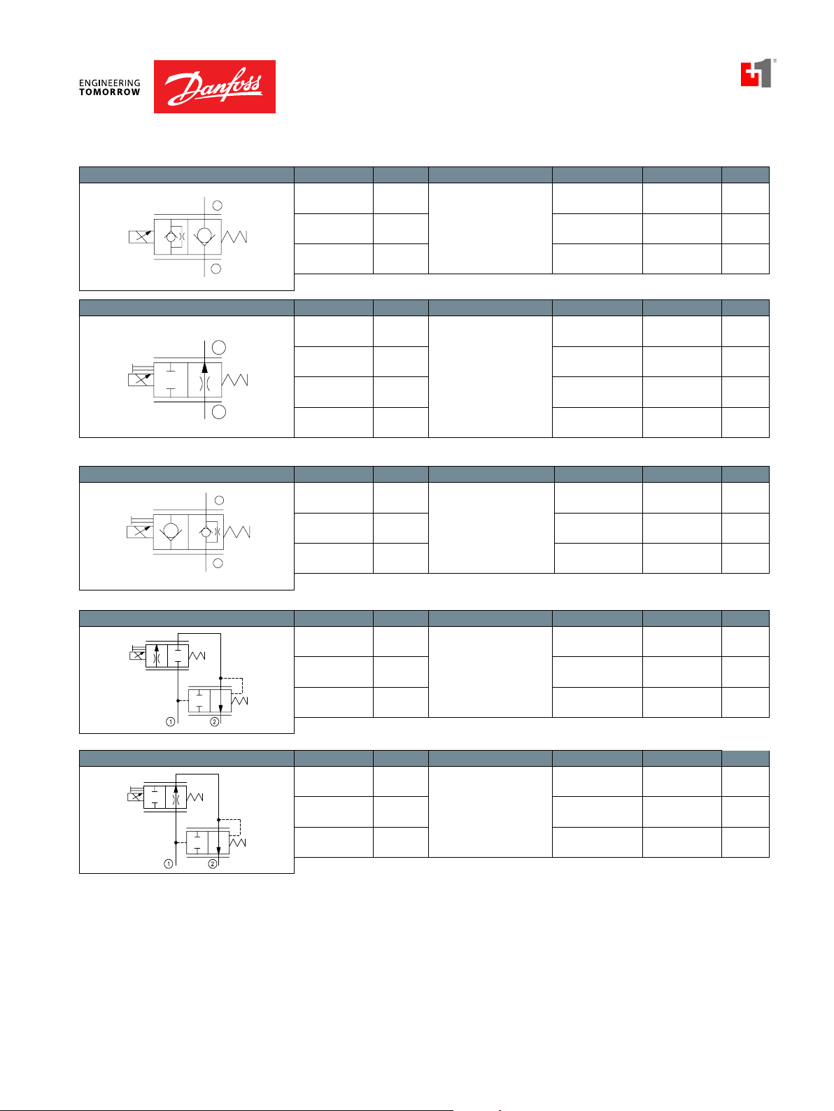
Proportional Flow Controls Model No. Cavity Description Flow* Pressure Page
CP518-PNC SDC08-2 Proportional Flow
Control Valve, Non-
12 l/min
[3 US gal/min]
210 bar
[3000 psi]
PV - 27
Compensated, Normally
PSV10-NC SDC10-2 40 l/min
PSV12-NC SDC12-2 80 l/min
PSV16-NC SDC16-2 100 l/min
* Flow ratings are based on a pressure drop of 7 bar [100 psi] unless otherwise noted. They are for comparison
Closed
[11 US gal/min]
[21 US gal/min]
[26 US gal/min]
260 bar
[3770 psi]
260 bar
[3770 psi]
260 bar
[3770 psi]
PV - 28
PV - 29
PV - 30
purposes only.
BC332375973113en-000101 • February 2020
PV - 1
Page 2
Proportional Valves Technical Information
1
2
1
2
2
1
Quick Reference
Proportional Flow Controls Model No. Cavity Description Flow* Pressure Page
PSVP10-NCR SDC10-2 Proportional Flow
Control Valve, Non-
PSVP12-NCR SDC12-2 70 l/min
PSVP16-NCR SDC16-2 90 l/min
Proportional Flow Controls Model No. Cavity Description Flow* Pressure Page
CP518-PNO SDC08-2 Proportional Flow
PSV10-NO SDC10-2 45 l/min
PSV12-NO SDC12-2 100 l/min
PSV16-NO SDC12-2 110 l/min
Proportional Flow Controls Model No. Cavity Description Flow* Pressure Page
PSVP10-NOR SDC10-2 Proportional Flow
PSVP12-NOR SDC12-2 70 l/min
PSVP16-NOR SDC16-2 80 l/min
Compensated, Normally
Closed, Poppet Type
Control Valve, NonCompensated, Normally
Open
Control Valve, NonCompensated, Normally
Open, Poppet Type
55 l/min
[14 US gal/min]
[18 US gal/min]
[24 US gal/min]
12.1 l/min
[3.2 US gal/min]
[12 US gal/min]
[26 US gal/min]
[29 US gal/min]
45 l/min
[12 US gal/min]
[18 US gal/min]
[21 US gal/min]
260 bar
[3770 psi]
260 bar
[3770 psi]
260 bar
[3770 psi]
210 bar
[3000 psi]
260 bar
[3770 psi]
260 bar
[3770 psi]
260 bar
[3770 psi]
260 bar
[3770 psi]
260 bar
[3770 psi]
260 bar
[3770 psi]
PV - 31
PV - 32
PV - 33
PV - 34
PV - 35
PV - 36
PV - 37
PV - 38
PV - 39
PV - 40
Proportional Flow Controls Model No. Cavity Description Flow* Pressure Page
PFC10-RC SDC10-2 Proportional Flow
Control Valve, Pressure
PFC12-RC SDC12-2 65 l/min
PFC16-RC SDC16-2 90 l/min
Proportional Flow Controls Model No. Cavity Description Flow* Pressure Page
PFC10-RO SDC10-2 Proportional Flow
PFC12-RO SDC12-2 60 l/min
PFC16-RO SDC16-2 85 l/min
Compensated,
Restrictive Type,
Normally Closed
Control Valve, Pressure
Compensated,
Restrictive Type,
Normally Open
30 l/min
[8 US gal/min]
[17 US gal/min]
[24 US gal/min]
30 l/min
[8 US gal/min]
[16 US gal/min]
[22 US gal/min]
260 bar
[3770 psi]
260 bar
[3770 psi]
260 bar
[3770 psi]
260 bar
[3770 psi]
260 bar
[3770 psi]
260 bar
[3770 psi]
PV - 41
PV - 42
PV - 43
PV - 44
PV - 45
PV - 46
Quick Reference
* Flow ratings are based on a pressure drop of 7 bar [100 psi] unless otherwise noted. They are for comparison
purposes only.
BC332375973113en-000101 • February 2020
Page 3
Proportional Valves Technical Information
3
1
2
Quick Reference
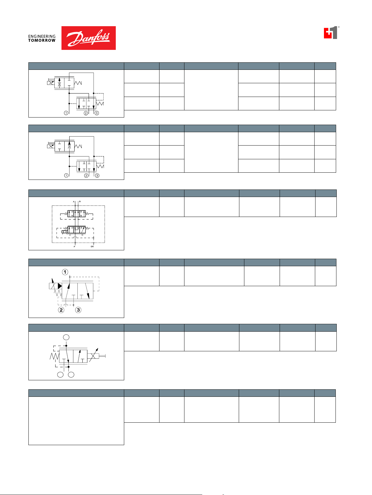
Proportional Flow Controls Model No. Cavity Description Flow* Pressure Page
PFC10-PC SDC10-3 Proportional Flow
Control Valve, Pressure
PFC12-PC SDC12-3 65 l/min
PFC16-PC SDC16-3 85 l/min
Proportional Flow Controls Model No. Cavity Description Flow* Pressure Page
PFC10-PO SDC10-3 Proportional Flow
PFC12-PO SDC12-2 70 l/min
PFC16-PO SDC16-3 90 l/min
Proportional Flow Divider Model No. Cavity Description Flow* Pressure Page
PFD10-OD CIB Proportional FLow
Compensated, Priority
Type, Normally Closed
Control Valve, Pressure
Compensated, Priority
Type, Normally Open
Divider, Compensated,
Catalog HIC
Quick Reference
40 l/min
[11 US gal/min]
[17 US gal/min]
[22 US gal/min]
35 l/min
[9 US gal/min]
[18 US gal/min]
[24 US gal/min]
40 l/min
[11 US gal/min]
260 bar
[3770 psi]
260 bar
[3770 psi]
260 bar
[3770 psi]
260 bar
[3770 psi]
260 bar
[3770 psi]
260 bar
[3770 psi]
230 bar
[3335 psi]
PV - 47
PV - 48
PV - 49
PV - 50
PV - 51
PV - 52
PV - 53
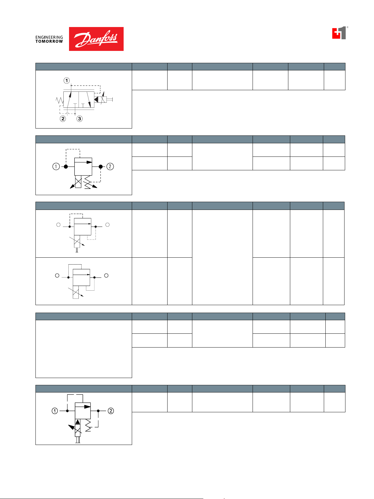
Proportional Pressure Reducing Model No. Cavity Description Flow* Pressure Page
PPR10-PAC SDC10-3 Proportional Pressure
Reducing/Relieving Valve,
Piloted
Proportional Pressure Reducing Model No. Cavity Description Flow* Pressure Page
CP558-24 SDC08-3 Proportional Pressure
Reducing Valve,
Direct Acting
Proportional Pressure Reducing Model No. Cavity Description Flow* Pressure Page
PPR09-POD SDC10-4 Proportional Pressure
Reducing/Relieving
Valve,
Piloted
18 l/min
[5 US gal/min]
4 l/min
[1 US gal/min]
25 l/min
[7 US gal/min]
250 bar
[3625 psi]
34 bar
[500 psi]
50 bar
[700 psi]
PV - 55
PV - 56
PV - 57
* Flow ratings are based on a pressure drop of 7 bar [100 psi] unless otherwise noted. They are for comparison
purposes only.
BC332375973113en-000101 • February 2020
PV - 3
Page 4
Proportional Valves Technical Information
1
2
12
Quick Reference
Proportional Pressure Reducing Model No. Cavity Description Flow* Pressure Page
XRP 06 NCS06/3 Proportional Pressure
Reducing/Relieving Valve,
Piloted
Proportional Pressure Relieving Model No. Cavity Description Flow* Pressure Page
PRV08-DAC SDC08-2 Proportional Pressure
Relief Valve,
HPRV08-DAC SDC08-2 1.89 l/min
Direct Acting,
Normally Closed
25 l/min
[7 US gal/min]
3.78 l/min
[1.0 US gal/min]
[0.5 US gal/min]
315 bar
[4500 psi]
215 bar
[3120 psi]
350 bar
[5075 psi]
PV - 59
PV - 60
PV - 61
Proportional Pressure Relieving
Proportional Pressure Relieving Model No. Cavity Description Flow* Pressure Page
Model No. Cavity Description Flow* Pressure Page
XMD 04 NCS04/2 Proportional Pressure
Relief Valve,
Direct Acting,
Normally Open
CP558-20 SDC08-2 8 l/min
PRV10-POC SDC10-2 Proportional Relief Valve,
Pilot Operated,
PRV12-POC SDC12-2 180 l/min
Normally Closed
5 l/min
[1.3 US gal/min]
[2 US gal/min]
76 l/min
[20 US gal/min]
[48 US gal/min]
250 bar
[3600 psi]
210 bar
[3000 psi]
250 bar
[3600 psi]
250 bar
[3600 psi]
PV - 62
PV - 63
PV - 64
PV - 65
Quick Reference
Proportional Pressure Relieving Model No. Cavity Description Flow* Pressure Page
* Flow ratings are based on a pressure drop of 7 bar [100 psi] unless otherwise noted. They are for comparison
purposes only.
BC332375973113en-000101 • February 2020
XMP 06 NCS06/2 Proportional Relief Valve,
Pilot Operated,
Normally Open
50 l/min
[13 US gal/min]
315 bar
[4500 psi]
PV - 66
Page 5

Proportional Valves Technical Information
Application Notes
Application Notes
PROPORTIONAL VALVES
Proportional, or electro-proportional valves, provide infinitely variable control of flow,
pressure, or direction, in response to a electric input signal.
There are four basic types of Danfoss ICS proportional valves:
• Flow control valves.
• Pressure reducing/relieving valves.
• Pressure relief valves.
• Directional control valves
Proportional valves
PLUS+1™ COMPLIANT Danfoss ICS solenoid valves are PLUS+1™ compliant. PLUS+1 compliance means our
valves are directly compatible with the PLUS+1 machine control architecture. Adding
solenoid valves to your application using PLUS+1 GUIDE software is as easy as drag-
and-drop. Software development that used to take months can now be done in just a
few hours. For more information on PLUS+1 GUIDE, visit http://powersolutions.danfoss.
com/Applications/PLUS1Compliance/index.htm. The table below details available GUIDE
function blocks for controlling Danfoss ICS solenoid valves.
GUIDE function blocks
Two-way proportional 10106103
Three-way proportional 10106104
BC332375973113en-000101 • February 2020
PV - 5
Page 6
Proportional Valves Technical Information
Restrictive-type circuit Priority-type circuit
Application Notes
PROPORTIONAL FLOW
CONTROL VALVES
Danfoss ICS proportional flow control valves are 2-way, spool-type valves that are
directly operated with a proportional electromagnetic solenoid actuator. By controlling
electric current, these valves create an infinitely variable orifice.
Proportional flow control valve
These valves are designed to be used with a logic element to provide pressure
compensation. Pressure compensation provides two advantages:
1. A constant pressure differential is maintained across the proportional valve (variable
orifice), which maintains constant flow regardless of changes in operating pressure
or load.
Typical flow versus pressure drop
2. A constant pressure differential
across the proportional valve limits
with compensation
without compensation
the flow forces acting on the valve
spool. At high flow and pressure,
Flow
the electromagnetic and spring
forces can be insufficient to maintain
valve operation without pressure
compensation.
Pressure drop
Application Notes
BC332375973113en-000101 • February 2020
Typical circuits use restrictive-type or priority-type pressure compensators with
proportional flow control valves to control speed of a hydraulic motor or cylinder.
Proportional flow control valves are available with a variety of flow capabilities (variable
orifice sizes). By matching this flow capability to various pressure compensator settings,
a wide range of flow vs. current control curves can be attained.
Typical circuit using a proportional valve
OutBypassOut
Flow
In In
Flow versus current
10.3 bar [150 psi]
6.9 bar [100 psi]
3.4 bar [50 psi]
Current
Effect of pressure compensator setting
Page 7
Proportional Valves Technical Information
AB
Application Notes
Application Notes
PROPORTIONAL
PRESSURE REDUCING/
RELIEVING VALVES
Proportional pressure reducing/relieving valves are 3-way valves that provide a
controlled output pressure as a function of electric current, regardless of system pressure
or flow (within the valve’s limits). Direct acting designs are available for low-flow
applications.
Direct-acting, proportional, pressure reducing valve
Proportional pressure reducing valves
Clutch pressure control
have a variety of applications including:
• Single acting cylinder position
control, e.g. combine header height
control.
• Clutch or brake pressure control.
• Pilot signal to a directional control
valve. By slowly ramping the current
P
to the proportional valve in this
example, a soft-start and soft-stop is
attained.
Single-acting cylinder piston control
Pilot signal to directional spool valve
W
High flow proportional pressure reducing valve functions can be created by using a
proportional valve to pilot a differential sensing valve; see differential sensing valve
application notes for more information.
BC332375973113en-000101 • February 2020
P
TP
PV - 7
Page 8

Proportional Valves Technical Information
Pressur
e
B
X
X
L1
S
L2
M2
Application Notes
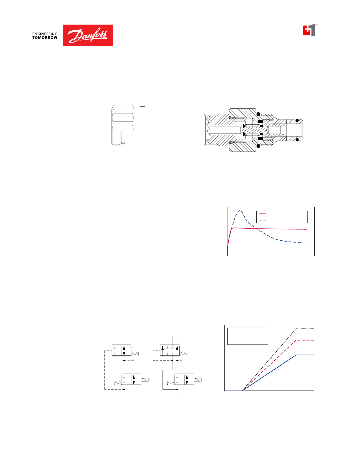
PROPORTIONAL
PRESSURE RELIEF
VALVES
Proportional pressure relief valves
are 2-way valves that provide a relief
Normally closed versus normally open
proportional relief valves
pressure as a function of electric current.
Both normally-open (increasing pressure
with increasing current), and normallyclosed (decreasing pressure with
increasing current) are available.
The normally-open proportional relief
valve is a direct-acting design for low
flow applications. High flow normallyopen proportional relief valve functions
can be created by using a proportional
valve to pilot a differential sensing valve;
see differential sensing valve application notes for more information.
Normally-open proportional relief valve
P
T
Normally-Open
Normally-Closed
Current
Common applications for normally-open proportional relief valves are:
Application Notes
• Electro-proportional control of system relief pressure; see differential sensing valve
application notes for more information.
• Electro-proportional remote pressure compensator control for open circuit piston
pumps (for more information refer to BLN-10128 Series 45 Open Circuit Axial Piston
Pumps Technical Information).
Remote pressure compensator pump control
BC332375973113en-000101 • February 2020
Page 9
Proportional Valves Technical Information
Application Notes
Application Notes
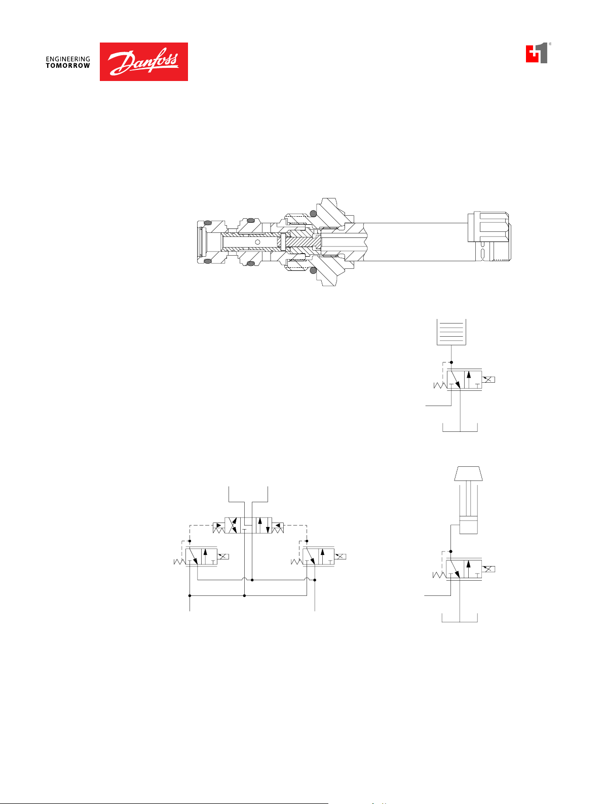
PROPORTIONAL
PRESSURE RELIEF
VALVES
(continued)
Normally-closed proportional relief valves are available in direct-acting and pilotoperated designs. A direct-acting, normally-closed proportional relief valve is used for
low flow applications. For high flow applications, internally pilot-operated cartridges are
available.
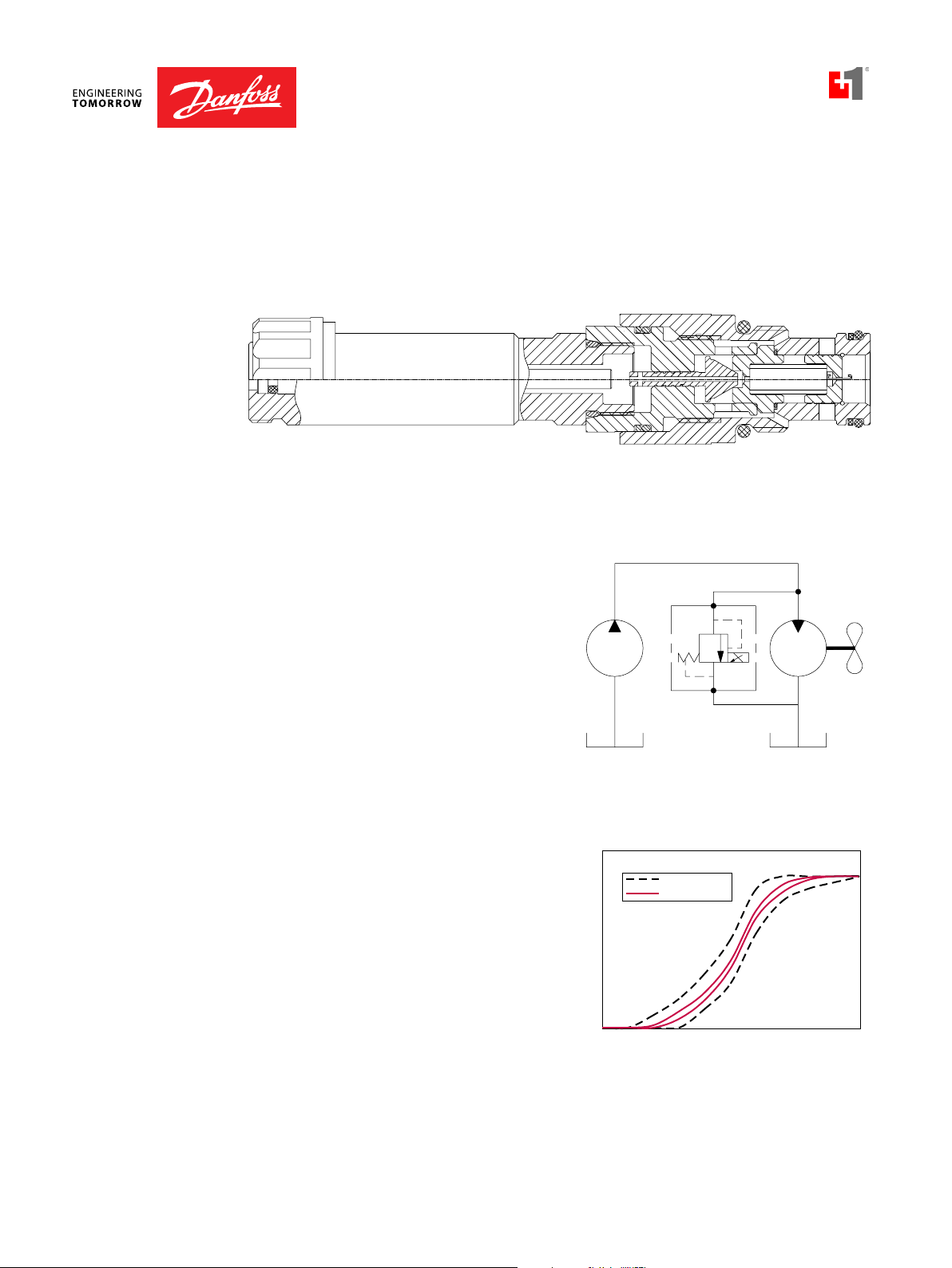
Internally pilot-operated cartridge for high flow applications
Common applications for normally-closed proportional relief valves are:
• Electro-proportional control of
Cooling fan speed control
system relief pressure or electroproportional remote pressure
compensator control for open circuit
piston pumps as above, but where
system requirements dictate full
pressure with no electrical signal.
ELECTRICAL
REQUIREMENTS
• Cooling fan speed control in
hydrostatic fan drive systems. (For
more information refer to BLN-10080
Fan Drives Systems and Components
Technical Information).
All proportional cartridge valves are
Proportional valve hysteresis
analog-type valves that control flow
or pressure as a function of electric
current. For this reason, proportional
valves should be driven with a current-
e
Direct current
PWM signal
controlled device that will maintain
constant output regardless of changes
in system voltage, line losses, or
ow or pressur
Fl
temperature. Typically available currentcontrolled valve drivers output a pulsewidth-modulated (PWM) square-wave
signal. An advantage of a PWM signal is
that the dither it provides significantly
Current
Typical performance
reduces hysteresis. Danfoss ICS recommends using a 100-200 Hz dither for best
performance.
BC332375973113en-000101 • February 2020
PV - 9
Page 10
Proportional Valves Technical Information
Current
Application Notes
TERMS AND
DEFINITIONS
Compensator is a hydraulic component that maintains a constant pressure drop across
a fixed or variable orifice.
Current is the flow of electricity through a conductor or coil, normally measured in amps
(A). Steady-state current flow in an electrical circuit can be calculated by Ohm’s Law, as
well as voltage and resistance.
Ohm’s Law I =
V
R
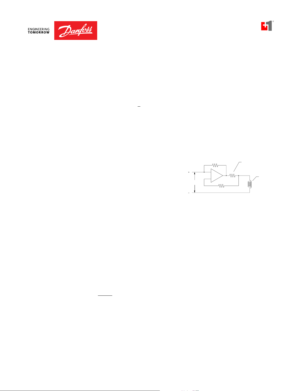
Current Control is a feature of almost all valve drivers. The output of analog
proportional valves is a direct function of current. If a valve is controlled with voltage,
higher solenoid temperatures, which increase solenoid resistance, will result in lower
valve output. To compensate for this, most valve drivers are designed with current
feedback circuitry. This means that as solenoid temperature rises or as supply voltage
and voltage losses change, the current
and corresponding valve output are
maintained.
Deadband is the range from zero to the
minimum current which causes the valve
Current feedback circuit
Input
sensing
resistor
Solenoid
to respond.
Digital Proportional Valves are
extremely fast responding valves that are controlled by a precise on-off signal to
produce an average output that is a function of duty cycle.
Application Notes
Dither is a “ripple” signal sent to a solenoid to reduce hysteresis. Dither can be a sine,
square, or saw-tooth wave superimposed on a PWM signal or it can be a wave on top of
a DC signal.
Duty Cycle is the % of time the valve is on divided by total time.
Hysteresis is the difference in output for a given input, depending on whether the
input is increasing or decreasing. It is normally expressed as a % of the maximum
rated output. For example, if a 160 l/min 42 US gal/min proportional flow control valve
provides 80 l/min 21 US gal/min with 1 amp-increasing and 88 l/min 23 US gal/min at 1
amp-decreasing, the hysteresis is:
(88-80)
= 5%
160
I
is the minimum current required for valve response (see deadband).
min
I
is the current required for maximum valve output.
max
Proportional Valves are analog devices controlled by electric current which may be
direct current (DC) or a PWM signal.
BC332375973113en-000101 • February 2020
Page 11

Proportional Valves Technical Information
Application Notes
Application Notes
TERMS AND
DEFINITIONS
(continued)
PWM is an acronym for Pulse-Width-Modulation. Most valve drivers use a current
controlled PWM which produces an average output that is a function of duty cycle in
order to reduce valve hysteresis and to allow current control without excessive heat
generation. A typical PWM output is a square wave from 80-500 Hz.
Ramping is the application of current to a solenoid with a linear or non-linear ramp,
rather than an instantaneous step. Ramping current on and off to a proportional valve
provides actuators with soft-starts and soft-stops. Ramps can generally be set or preprogrammed into valve drivers.
Resistance is a component’s opposition to the flow of electrical current, usually
measured in ohms (Ω). Resistance depends on the conductivity of the material, as well
as size, shape, and temperature. Solenoid resistance can vary greatly with temperature;
to compensate for this, current-controlled drivers are generally always used with
proportional valves.
Threshold is the minimum current required for valve response; see deadband.
Valve Driver is a generic term for any device that sends a signal to a proportional valve.
A valve driver may range from a simple electronic circuit attached to a knob or lever up
to a microcontroller with custom software and multiple inputs and outputs.
Voltage is the potential for current to flow in an electric circuit, usually measured in
volts (V).
BC332375973113en-000101 • February 2020
PV - 11
Page 12
Proportional Valves Technical Information
NEUTRAL
58.75
126.5
185.85 from spot face
from spot face
Application Notes
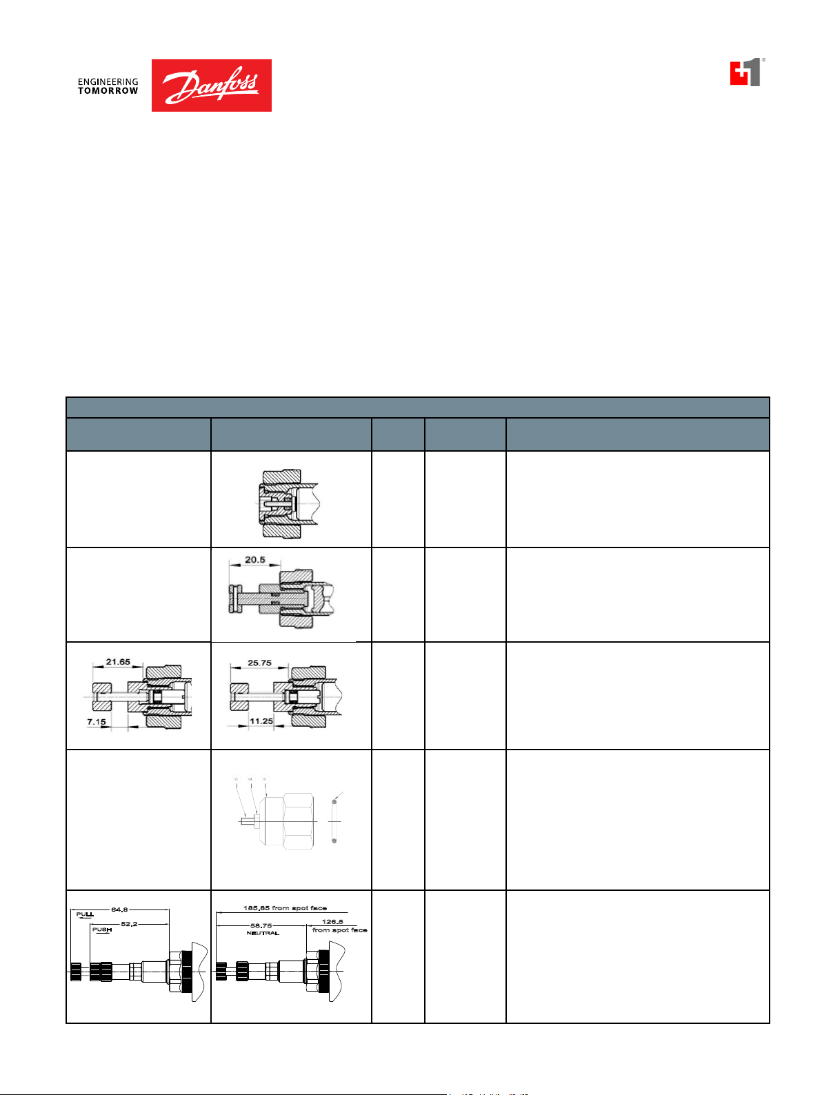
MANUAL OVERIDE
MANUAL OVERIDES
OPTIONS
Danfoss ICS proportional flow control valves, where noted in the individual
catalog pages, have optional manual overrides - “SPS” and “PB” (note
that it if the valve has a manual override option, it comes standard with
a push-pin style override). The manual overrides are “safety” features for
when power is lost and the proportional valve needs to be operated. If
using the “SPS” option, the screw-style manual override can be used to
proportionally adjust the flow setting when no power is supplied to the
coil. When using the “PB” option, the push-button manual override will
push to fully open or fully close the valve, which can send full flow, or
cut-off the flow to the system. So caution must be taken when applying
in a proportional system. The “SPS” proportional control is preferred. The
manual overrides, when activated, shift the valve to its energized position.
MANUAL OVERRIDE OPTIONS
Override Activated Normal Position Size Order Code Description
(mm) (mm)
10, 12,
16 Sizes
OMIT
(PN for HSV’s)
Standard for any valve with push-pin manual
override feature, where indicated in the catalog.
PB
10, 12,
Push Button
16 Sizes
SPS
10, 12,
16 Sizes
04 and
06 Sizes
Screw Style
(Push Type
Valves)
EN
Screw style
(metric)
64.8
PULL
PUSH
52.2
10 Size
PAP
(Push and Pull)
Optional feature for any valve with push-pin manual
override.
Optional feature for any valve with push-pin manual
override. Part number for SPS Manual Override Kit is
272601688.
Optional feature for screw adjustment for
proportional valves (XMD 04 and XMP 06)
Optional feature for push and pull functionality
on the 3 position, 4-way type proportional valves
(PSV10-34-XX)
Application Notes
BC332375973113en-000101 • February 2020
Page 13
Proportional Valves Technical Information
S2
S1
2
1
4
3
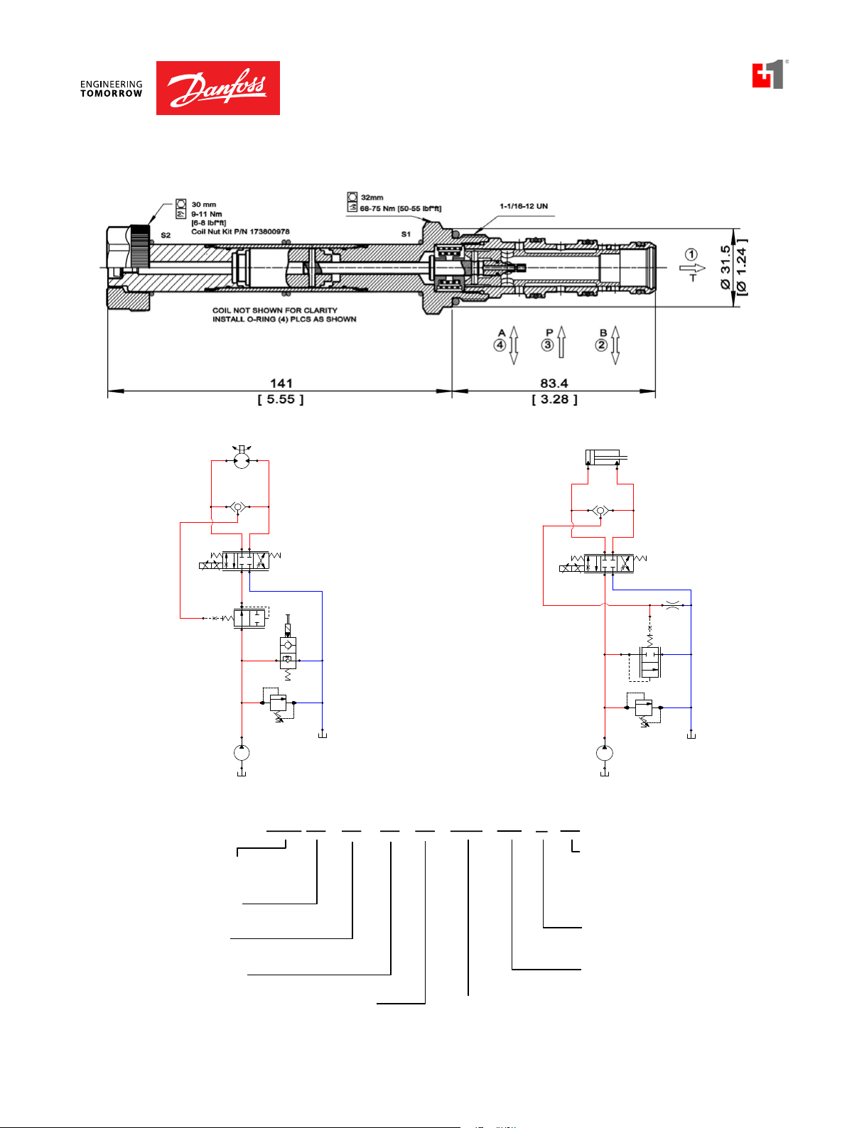
Proportional Directional
PSV10-34-02
OPERATION
This is a proportional, non-compensated, 3 position 4 way,
directional flow control solenoid valve, with closed-center
spool.
APPLICATION NOTES
These cartridge valves are typically applied to provide bi-directional,
proportional control of hydraulic cylinders and motors where low
leakage is not required. For load-independent flow control, apply with
a pressure compensator, such as CP700-4 (see Example Circuit). Port 1
should be used as the tank port, with a maximum back-pressure of 150
bar. For applications with unequal flows, the highest flow should be
connected to Port 2.
Note: For optimal performance install with the solenoid valve below
the tank oil level in the horizontal position, reducing the chance for
trapped air in the valve.
SPECIFICATIONS
Rated Pressure* 250 bar [3600 psi]
Maximum Rated Flow at 10 bar
[145 psi]
Weight including coil 0.77 kg [1.7 lbs]
Hysteresis 4% maximum
Threshold current 0.5 A (12 VDC coil)
Maximum control current 1.5 A (12 VDC coil)
DIMENSIONS
Cavity SDC10-4
Standard Coil M16 26 Watt
Robust Coil R16 20 Watt
22 l/min
[6 US gal/min]
0.25 A (24 VDC coil)
0.8 A (24 VDC coil)
Robust Nut P/N 173804910
(no coil O-rings needed)
Shown with standard coils,
DIN connectors
Shown with Robust Coil
SCHEMATIC
THEORETICAL PERFORMANCE
Operating curves with M16 coil and plastic nut
* Rated Pressure based on NFPA fatigue test standards (at 1 Million Cycles).
BC332375973113en-000101 • February 2020
Operating curves with R16 coil and steel nut
PV - 13
Page 14
Proportional Valves Technical Information
Cavity Size:
Schematic:
Type
Max Regulated Flow:
Housing and Ports:
Housing P/N:
Seals: Seal Kit
Coil TerminationCoil Voltage:
10 = Size 10
34 = 3 Position, 4 Way
02 = Closed Center Spool
00 = No Coil
12D = 12 VDC
24D = 24 VDC
R12D = 12 VDC R-Coil
R24D = 24 VDC R-Coil
12 = 12 LPM (3 GPM)
22 = 22 LPM (6 GPM)
00 = No coil, with Nut
AJ = AMP Junior*
AS = AMP SuperSeal 1.5
DE = Deutsch
DN = DIN 46650*
FL = Flying Leads
*These terminations are not available
on robust coil (R12D, R24D)
B = Buna-N 354001919
V = Viton 354002019
00 = No Housing
L3B = AL 3/8 BSP
L4B = AL, 1/2 BSP
6S = AL #6 SAE
8S = AL, #8 SAE
Other housings available
PSV 10 - 34 - 02 - 12D
-
DE
-
22
-
PAP - B - 00
Proportional Solenoid
Valve, Non-compensated
Flow Control
No Housing
SDC10-4-L-3B
SDC10-4-L-4B
CP10-4-6S
CP10-4-8S
Manual Override:
Omit = No Override
PAP = Push and Pull Override**
**Consult Factory for Details
Proportional Directional
PSV10-34-02
DIMENSIONS
mm [in]
24mm
9-11 Nm [6-8 lbf*ft]
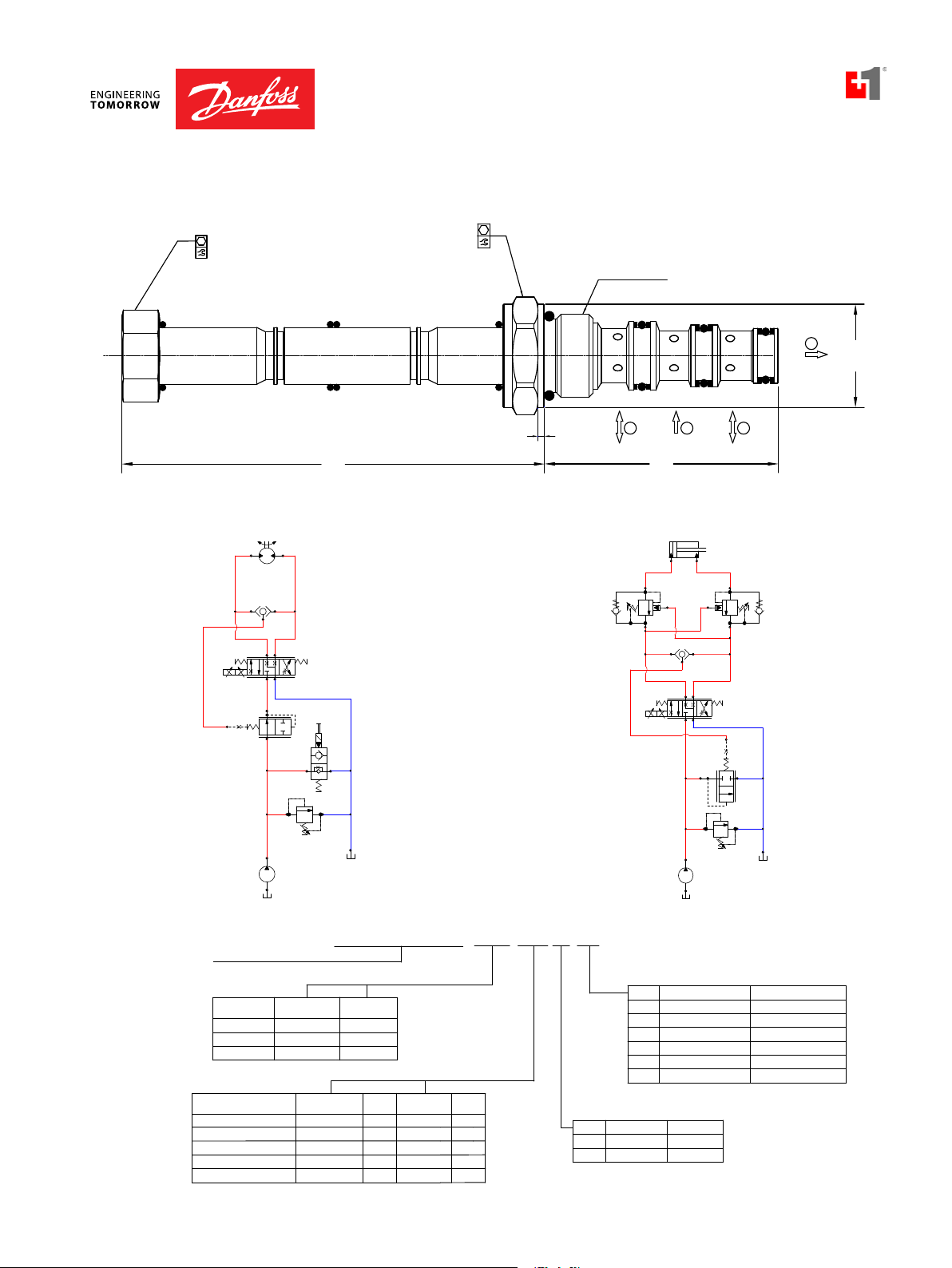
EXAMPLE CIRCUITS
Pressure Compensated Bi-directional Proportional Motor Control Double Acting Cylinder with Proportional Speed Control
Cross-sectional view
45-50 Nm [33-37 lbf*ft]
Coil Nut KIT P/N 17400031
COILS NOT SHOWN FOR CLARITY
INSTALL O-RINGS (4) PLCS AS SHOWN
127.25
[5.01]
27mm
S1S2
[0.20]
7/8-14 UNF 2A
4
3
2
1
Ø26.5
5
62
[2.44]
[Ø1.04]
CP124-1
PSV10-34-02
CP700-4
SVP08-NO
RV08-DR
ORDERING INFORMATION
BC332375973113en-000101 • February 2020
CP124-1
PSV10-34-02
CP700-1
RV08-DR
Page 15
Proportional Valves Technical Information
S2
S1
2
1
4
3
)
)
Operating curves with M19 coil and nut.
Curves made with a logic element set at 10 Ba
26 cSt [121 SUS] hyd.oil@50C [122F
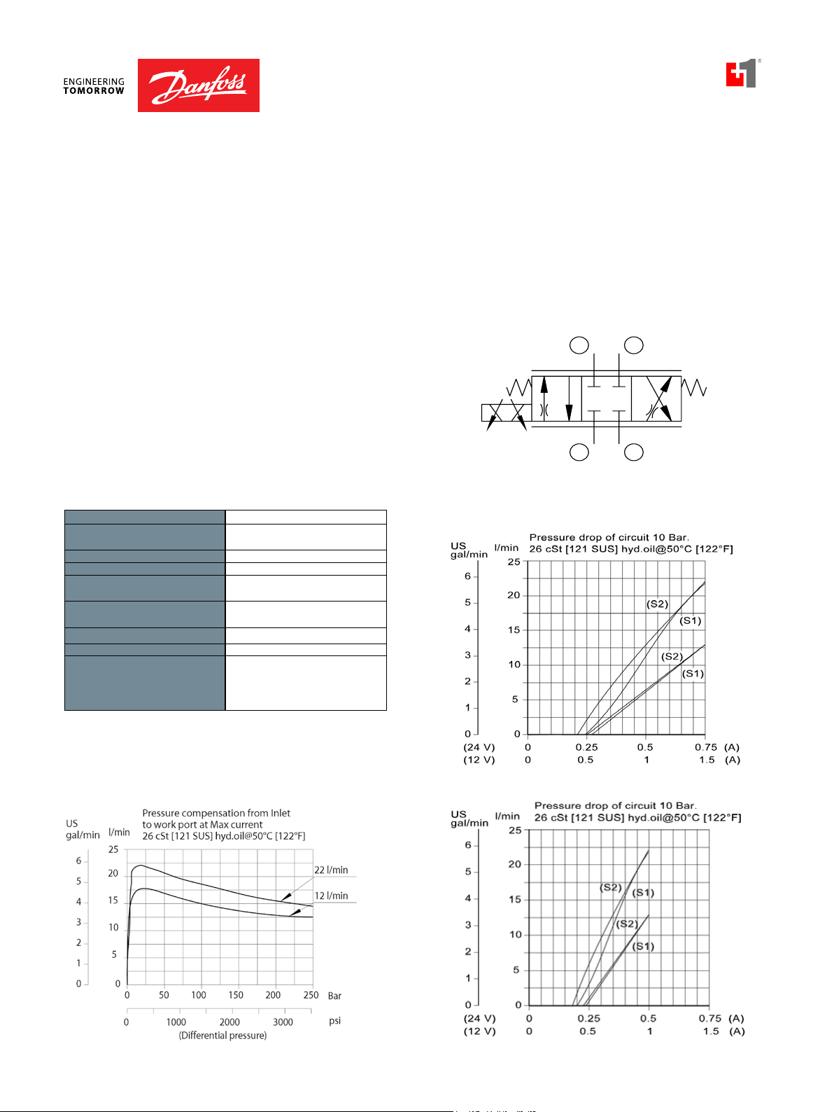
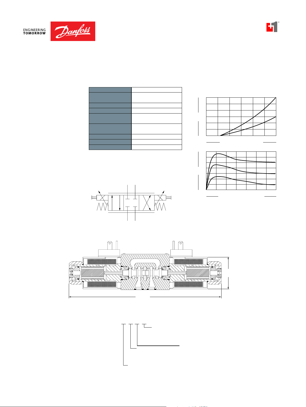
Proportional Directional
PSV12-34-02
OPERATION
This is a proportional, non-compensated, 3 position 4 way, directional
Shown with Deutsch
connector
flow control solenoid valve, with closed-center spool.
APPLICATION NOTES
These cartridge valves are typically applied to provide bi-directional,
proportional control of hydraulic cylinders and motors where low
leakage is not required. For load-independent flow control, apply with
a pressure compensator, such as HLE10-OPO (see Example Circuit). Port
1 should be used as the tank port, with a maximum back-pressure of
150 bar. For applications with unequal flows, the highest flow should be
connected to Port 2.
Note: For optimal performance install with the solenoid valve below the
tank oil level in the horizontal position, reducing the chance for trapped
air in the valve.
SPECIFICATIONS SCHEMATIC
Rated Pressure* 260 bar [3770 psi]
Rated Flow at 10 bar
[145 psi]
Weight including coil 1.2 kg [2.64 lbs]
Hysteresis <4%
Threshold current 0.25 A (12 VDC coil)
DIMENSIONS
Maximum control
current
Cavity CP12-4
Standard Coil M19 33 Watt
* Rated Pressure based on NFPA fatigue test standards (at 1 Million Cycles).
50 l/min
[13 US gal/min]
0.50 A (24 VDC coil)
1.8 A (12 VDC coil)
0.9 A (24 VDC coil)
Shown with DIN
connector
THEORETICAL PERFORMANCE
BC332375973113en-000101 • February 2020
US
gal/min
18
12
6
0
l/min
(24 V)
(12 V)
60
40
20
r.
]
(50)
(30)
0.30
0.60
0.6
1.2
0.9 (A
1.8 (A
PV - 15
Page 16
Proportional Valves Technical Information
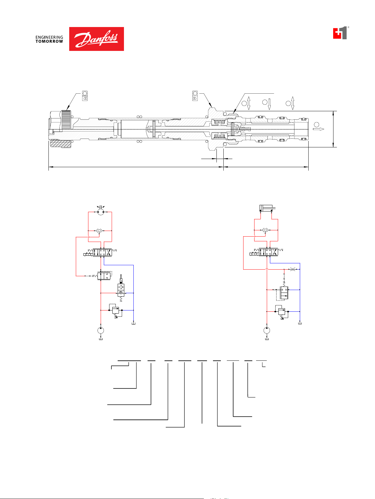
PSV12-34-02
CP124-1
HLE10-CPC
CP200-1
Proportional Directional
PSV12-34-02
DIMENSIONS
mm [in]
EXAMPLE CIRCUITS
Pressure Compensated Bi-directional Proportional Motor Control Double Acting Cylinder with Proportional Speed Control
Cross-sectional view
ORDERING INFORMATION
CP124-1
PSV12-34-02
HLE10-OPO
CP200-1
Proportional Solenoid
Valve, Non-compensated,
Flow Control
Cavity Size:
12 = Size 12
Type :
34 = 3 Position, 4 W ay
Schematic:
02 = Closed Center Spool
SVP10-NO
12
PSV
Max Regulated Flow:
30 = 30 LPM (8 GPM)
50 = 50 LPM (13 GPM)
- 34
-
-
50
-
-
12D
Coil Voltage:
00 = No Coil
12D = 12 VDC
24D = 24 VDC
02
-
B
- 00DE
Housing and Ports: Housing P/N:
00 = No Housing
3B = AL, 3/8 BSP
4B = AL, 1/2 BSP
8S = AL, #8 SAE
10S = AL, #10 SAE
*Other housings available
Seals: Seal Kits:
B = Buna-N 11106420
V = Viton 11106444
Coil Termination:
00 = No coil, with Nut
AJ = AMP Junior
AS = AMP SuperSeal 1.5
DE = Deutsch
DN = DIN 46650
FL = Flying Leads
No Housing
CP12-4-3B
CP12-4-4B
CP12-4-8S
CP12-4-10S
BC332375973113en-000101 • February 2020
Page 17
Proportional Valves Technical Information
gpm
6
gpm
P
T
A
B
PDCV03-3Z11/15-12-E1-8S
ll internal seals are viton
Proportional Directional
PDCV03-3Z11
OPERATION
SPECIFICATIONS
This valve is a proportional directional control.
Rated pressure 350 bar [5075 psi]
Rated flow at 10 bar
[145 psi]
30 l/min
[8 US gal/min]
Weight 2.40 kg [5.29 lb]
Hysteresis 6% maximum
Threshold current 0.5 A (12 VDC coil)
0.25 A (24 VDC coil)
Maximum control
current
2.4 A (12 VDC coil)
1.2 A (24 VDC coil)
Cavity ISO D03
Standard Coil PD03 40 Watt
Coil nut 158-8005
SCHEMATIC
THEORETICAL PERFORMANCE
154 SUS (33 cSt) hyd. oil @ 100° F (38° C)
L/min
30
8
25
7
20
5
15
4
Flow
10
3
51
0
L/min
35
9.2
30
7.9
25
6.6
20
5.3
Flow
15
4
10
2.6
51.3
0
at 10 bar [145 psi] pressure drop
e
d
o
C
C
0.4
0.8 1.2 1.622.4
Current, Amps (with 12VDC coil)
154 SUS (33 cSt) hyd. oil @ 100° F (38° C)
2
.
4
A
(
1
2
1
.
9
A
(
1
2
V
1
.
4
A V
(
1
2
bar
psi
100 150 200 250 300 350
50
Loop pressure drop (P ABT)
725
1450 2176 2901 3626 4351 507
0
3
=
1
=
e
d
o
V
c
o
i
l
)
c
o
i
l
)
c
o
i
l
)
5
DIMENSIONS
mm [in]
ORDERING
INFORMATION
Cross-sectional view
Nominal flow rate
215.9
[8.50]
Subplate option
OMIT= No subplate
8S = Aluminum, #8 SAE ports
S8S =Steel, #8 SAE ports
Voltage
12 = 12 VDC
24 = 24 VDC
15 = 15 L/min [4.0 gpm]
30 = 30 L/min [7.9 gpm]
Termination
E1 = DIN 43650
E3 = Amp Jr.
E8 = Lead wires
E12= Deutsch
E14= Dual spade
Ø 45.7
[1.80]
Seal Kit
B=Buna-N158-8007
V=Viton 158-8062
Note :A
Bolt Kit
#10-24 Thd. 158-8064
M5 Thd. 158-8026
Seal kit
BC332375973113en-000101 • February 2020
PV - 17
Page 18
Proportional Valves Technical Information
flow
P
T
A
B
318 mm
[12.52 in]
70 mm
[2.76 in]
Fl
n9
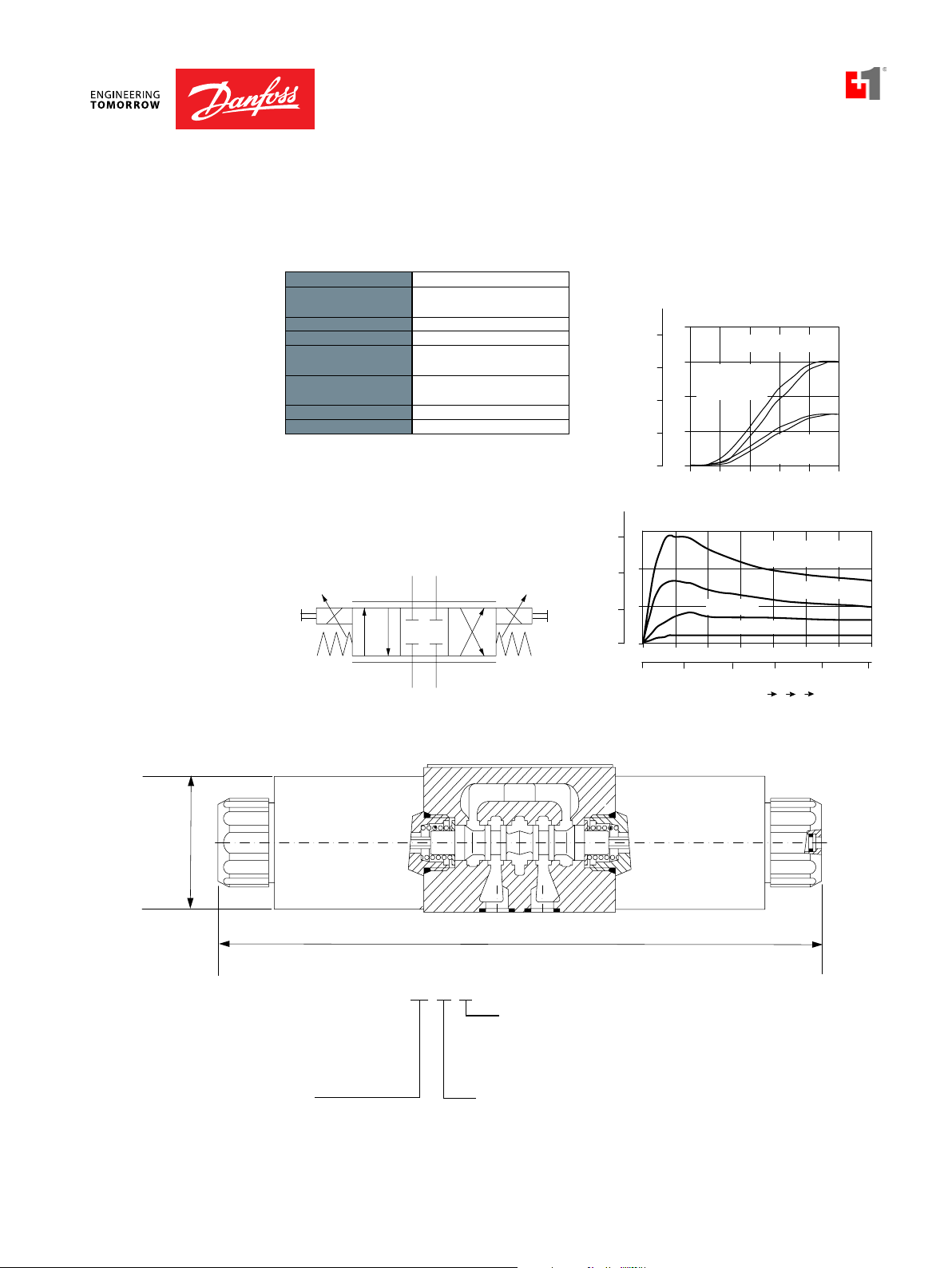
Proportional Directional
PDCV05-3Z11
OPERATION
SPECIFICATIONS
DIMENSIONS
mm [in]
This is a non-compensated proportional directional control valve.
THEORETICAL PERFORMANCE
Rated pressure 350 bar [5075 psi]
Rated Flow at 10 bar
[150 psi]
Weight 6.60 kg [14.60 lb]
Hysteresis 6% maximum
Threshold current 0.2 A (12 VDC coil)
Maximum control
current
60 l/min
[16 US gal/min]
0.1 A (24 VDC coil)
1.8 A (12 VDC coil)
0.9 A (24 VDC coil)
US gal/min
20
15
10
flow
26 cSt [125 SUS] hyd.oil @ 20° C [68° F]
l/min
80
60
At 10 bar
(145 psi)
pressure drop
40
Cavity ISO D05
Standard Coil PD05 23 Watt
15
l/min
60
20
5
0
0
SCHEMATIC
40
10
20
5
0
0
psi
50
bar
0
100
1000
Loop Pressure Drop P A BT
Cross-sectional view
flow vs current
Nominal flow=60 l/min
Nominal flow
=30 l/min
2.0
0.96 Amps
150
1.51.00.50
Current = 2.40 Amps
1.92 Amps
250
200
3000
Current, Amps (12VDC coil)
pressure drop
1.44 Amps
2000
3500
300
2.5
350
5000
ORDERING
INFORMATION
30 = 30 l/min [7.9 US gal/min]
60 = 60 l/min [15.8 US gal/min]
PDCV05-3Z11/30-12-E1
ow rate
Connector
E1 =DIN 43650
E8 =Lead wires
E10 =Deutsch on leads
Voltage
12 =12 VDC
24 =24 VDC
Seal kit
B=Buna N 158-8023
V=Vito
158-80
All internal seals areViton
Bolt kit
1/4-20 Thd 158-8095
M6 Thd 158-8024
4
BC332375973113en-000101 • February 2020
Page 19
Proportional Valves Technical Information
3 TO 2
3 TO 4
1
2
3
4
5
gal/min
0
(12 V)
(24 V)
1.5 (A)10.50
l/min
20
16
12
8
4
0.75 (A)0.50.25
0
0
Flow vs. Current
26 cSt [121 SUS] hyd.oil@50°C [122°F]
10 bar pressure drop
Pressure Compensation from Inlet to Work Port
26 cSt [121 SUS] hyd.oil@50°C [122°F]
Bar
250
l/min
12
9
6
3
20015010050
0
0
Differential pressure
300020000 1000
psi
0
US
gal/min
4
3
2
1
15
0.8 A
1.0 A
3
4
1
2
S1
S2
Proportional Directional
PSV08-34-05
OPERATION
This is a proportional, non-compensated, 3 position 4 way,
directional flow control solenoid valve, with float-center spool.
APPLICATION NOTES
These cartridge valves are typically applied to provide
bi-directional, proportional control of hydraulic cylinders and
motors. In applications requiring load-holding, PO checks or
counterbalance valves can be added to provide a low leakage
solution. For load-independent flow control, apply with a
pressure compensator, such as CP700-4 (see Example Circuit).
Port 1 should be used as the tank port, with a maximum backpressure of 150 bar. For applications with unequal flows, the
highest flow should be connected to Port 2.
Note: For optimal performance install with the solenoid valve
below the tank oil level in the horizontal position, reducing the
chance for trapped air in the valve.
Shown with Standard Coils,
Deutsch connectors
SPECIFICATIONS SCHEMATIC
Rated Pressure* 240 bar [3500 psi]
Maximum Rated Flow at 10 bar
[145 psi]
Weight including coil 0.55 kg [1.21 lbs]
Threshold current 0.5 A (12 VDC coil)
Maximum control current 1.0 A (12 VDC coil)
DIMENSIONS
Cavity
Standard Coil M13 20 Watt
Robust Coil R13 16 Watt
* Rated Pressure based on NFPA fatigue test standards (at 1 Million Cycles).
THEORETICAL PERFORMANCE
BC332375973113en-000101 • February 2020
12 l/min
[3.2 US gal/min]
0.25 A (24 VDC coil)
0.5 A (24 VDC coil)
SDC08-4
Robust Nut P/N 173800539
(no coil O-rings needed)
Operating curves with M13 coil and steel nut
PV - 19
Page 20
PSV08-34-05-12D-DE-B-00
Coil Termination
DIMENSIONS
24 mm
RV08-DR
CP124-1
PSV08-34-05
CP700-1
CP448-1CP448-1
mm [in]
Proportional Valves Technical Information
Proportional Directional
PSV08-34-05
Cross-sectional view
19 mm
3-4 Nm [26-35 lbf*in]
Coil Nut Kit P/N 11193677
(coil o-rings included)
EXAMPLE CIRCUITS
S2
COIL NOT SHOWN FOR CALRITY
INSTALL O-RING (4) PLCS AS SHOWN
97.0
[3.82]
24-28 Nm [17-20 lbf*ft]
S1
1.5
[0.06]
PSV08-34-05
3/4-16 UNF-2A
4
53.7
[2.11]
1
3
2
Pressure Compensated Bi-directional Proportional Motor Control Double Acting Cylinder with Proportional Speed Control
CP124-1
PSV08-34-05
Ø 23.7
[Ø 0.93]
CP700-4
ORDERING INFORMATION
Proportional Solenoid Valve
08-Size, 3 position, 4 way
Coil Voltage
Description
No Coil
12 VDC
24 VDC
Description
No Coil
Flying Lead
Deutsch
AMP SuperSeal 1.5
DIN 43650
SVP08-NO
RV08-DR
Standard Coil
Code
00
12D
24D
Standard Coil
Code
00
FL
DE
AS
DN
Robust Coil
Code
R00
R12D
R24D
IP
Rating
-
IP65
IP69K
IP67
IP65
Robust Coil
Code
00
FL
DE
AS
-
IP
Rating
-
IP69K
IP69K
IP69K
-
Seals
Code
Housings
Code
Ports & Material
Cartridge only
00
4S6S#4 SAE, AL
#6 SAE, AL
S6S
#6 SAE, Steel
1/4 BSP, AL SDC08-4-L2B
L2B
S3B
3/8 BSP, Steel CP08-4-S3B
Material
B
BUNA
V
VITON
Seal kit
354003319
354003919
Body Nomenclature
No Body
CP08-4-4S
CP08-4-6S
CP08-4-S6S
BC332375973113en-000101 • February 2020
Page 21

Proportional Valves Technical Information
Proportional Directional
PSV10-34-05
OPERATION
This is a proportional, non-compensated, 3 position 4 way,
directional flow control solenoid valve, with float-center spool.
APPLICATION NOTES
These cartridge valves are typically applied to provide
bi-directional, proportional control of hydraulic cylinders and
motors. In applications requiring load-holding, PO checks or
counterbalance valves can be added to provide a low leakage
solution. For load-independent flow control, apply with a
pressure compensator, such as CP700-4 (see Example Circuit).
Port 1 should be used as the tank port, with a maximum backpressure of 150 bar. For applications with unequal flows, the
highest flow should be connected to Port 2.
Note: For optimal performance install with the solenoid valve
below the tank oil level in the horizontal position, reducing the
chance for trapped air in the valve.
standard coil
SCHEMATIC
S1
Shown with Robust CoilShown with DIN connector,
2
3
4
S2
1
SPECIFICATIONS
Rated Pressure* 250 bar [3600 psi]
Maximum Rated Flow at 10 bar
[145 psi]
Weight including coil 0.77 kg [1.7 lbs]
Hysteresis 4% maximum
Threshold current 0.5 A (12 VDC coil)
Maximum control current 1.5 A (12 VDC coil)
DIMENSIONS
Cavity SDC10-4
Standard Coil M16 26 Watt
Robust Coil R16 20 Watt
* Rated Pressure based on NFPA fatigue test standards (at 1 Million Cycles).
22 l/min
[6 US gal/min]
0.25 A (24 VDC coil)
0.8 A (24 VDC coil)
Robust Nut P/N 173804910
(no coil O-rings needed)
THEORETICAL PERFORMANCE
Operating curves with M16 coil and plastic nut
Operating curves with R16 coil and steel nut
BC332375973113en-000101 • February 2020
PV - 21
Page 22

Cavity Size:
Type
Housing and Ports:
Housing P/N:
Seals: Seal Kit
Coil Termination
Coil Voltage:
10 = Size 10
34 = 3 Position, 4 Way
Schematic:
05 = Float Center Spool
00 = No Coil
12D = 12 VDC
24D = 24 VDC
R12D = 12 VDC R-Coil
R24D = 24 VDC R-Coil
Max Regulated Flow:
3 = 3 LPM (0.8 GPM)
12 = 12 LPM(3 GPM)
22 = 22 LPM (6 GPM)
00 = No coil, with Nut
AJ = AMP Junior*
AS = AMP SuperSeal 1.5
DE = Deutsch
DN = DIN 46650*
FL = Flying Leads
B = Buna-N 354001919
V = Viton 354002019
00 = No Housing
L3B = AL 3/8 BSP
L4B = AL, 1/2 BSP
6S = AL #6 SAE
8S = AL, #8 SAE
Other housings available
PSV 10 - 34- 05 - 12D
-
DE
-
22
-
PAP - B - 00
Proportional Solenoid
Valve, Non-compensated
Flow Control
No Housing
SDC10-4-L-3B
SDC10-4-L-4B
CP10-4-6S
CP10-4-8S
**Consult Factory for Details
Manual Override:
Omit = No Override
PAP = Push and Pull Override**
DIMENSIONS
RV08-DR
CP124-1
PSV10-34-05
CP700-1
CB10-HVCB10-HV
mm [in]
Proportional Valves Technical Information
Proportional Directional
PSV10-34-05
Cross-sectional view
24mm
9-11 Nm [6-8 lbf*ft]
45-50 Nm [33-37 lbf*ft]
Coil Nut KIT P/N 17400031
27mm
S1S2
7/8-14 UNF 2A
4
3
2
1
COILS NOT SHOWN FOR CLARITY
INSTALL O-RINGS (4) PLCS AS SHOWN
127.25
[5.01]
[0.20]
5
62
[2.44]
EXAMPLE CIRCUITS
Pressure Compensated Bi-directional Proportional Motor Control Double Acting Cylinder with Proportional Speed Control
CP124-1
PSV10-34-05
CP700-4
SVP08-NO
Ø26.5
[Ø1.04]
ORDERING INFORMATION
BC332375973113en-000101 • February 2020
RV08-DR
Page 23

Proportional Valves Technical Information
Proportional Directional
PSV12-34-05
OPERATION
This is a proportional, non-compensated, 3 position 4 way,
directional flow control solenoid valve, with float-center spool.
APPLICATIONS
These cartridge valves are typically applied to provide bi-directional,
proportional control of hydraulic cylinders and motors. In
applications requiring load-holding, PO checks or counterbalance
valves can be added to provide a low leakage solution. For loadindependent flow control, apply with a pressure compensator, such
as HLE10-OPO (see Example Circuit). Port 1 should be used as the
tank port, with a maximum back-pressure of 150 bar. For applications
with unequal flows, the highest flow should be connected to Port 2.
Shown with Deutsch
connector
Note: For optimal performance install with the solenoid valve below
the tank oil level in the horizontal position, reducing the chance for
trapped air in the valve.
SPECIFICATIONS SCHEMATIC
Rated Pressure* 260 bar [3770 psi]
Maximum Rated Flow at 10
bar [145 psi]
Weight including coil 1.2 kg [2.64 lbs]
Hysteresis 4% maximum
Threshold current 0.5 A (12 VDC coil)
Maximum control current 1.8 A (12 VDC coil)
DIMENSIONS
Cavity CP12-4
Standard Coil M19 33 Watt
* Rated Pressure based on NFPA fatigue test standards (at 1 Million Cycles).
60 l/min
[16 US gal/min]
0.25 A (24 VDC coil)
0.9 A (24 VDC coil)
THEORETICAL PERFORMANCE
S1
Shown with DIN
connector
2
4
S2
3
1
BC332375973113en-000101 • February 2020
PV - 23
Page 24

Proportional Valves Technical Information
Cavity Size:
Schematic:
Type:
Max Regulated Flow:
Housing and Ports: Housing P/N:
Seals: Seal Kits:
Coil Termination:
Coil Voltage:
12
12 = Size 12
34 = 3 Position, 4 Way
05 = Float Center Spool
00 = No Coil
12D = 12 VDC
24D = 24 VDC
30 = 30 LPM (8 GPM)
60 = 60 LPM (16 GPM)
00 = No coil, with Nut
AJ = AMP Junior
AS = AMP SuperSeal 1.5
DE = Deutsch
DN = DIN 46650
FL = Flying Leads
B = Buna-N 11106420
V = Viton 11106444
00 = No Housing
3B = AL, 3/8 BSP
4B = AL, 1/2 BSP
8S = AL, #8 SAE
10S = AL, #10 SAE
*Other housings available
- 34
-
05
60
-
12D
-
-
B
- 00DE
-
PSV
Proportional Solenoid
Valve, Non-compensated
Flow Control
No Housing
CP12-4-3B
CP12-4-4B
CP12-4-8S
CP12-4-10S
Proportional Directional
PSV12-34-05
DIMENSIONS
mm [in]
SPECIFICATIONS
EXAMPLE CIRCUITS
Pressure Compensated Bi-directional Proportional Motor Control Double Acting Cylinder with Proportional Speed Control
Cross-sectional view
CP124-1
PSV12-34-05
HLE10-OPO
ORDERING INFORMATION
CP200-1
SVP10-NO
CB10-HVCB10-HV
CP124-1
PSV12-34-05
HLE10-CPC
CP200-1
BC332375973113en-000101 • February 2020
Page 25

Proportional Valves Technical Information
gpm
6
gpm
T
P
Ø 45.7
[1.80]
215.9
[8.50]
PDCV03-3Y11/15-12-E1-8S
Proportional Directional
PDCV03-3Y11
OPERATION
SPECIFICATIONS
This valve is a proportional directional control.
Rated pressure 350 bar [5075 psi]
Rated Flow at 10 bar
[145 psi]
30 l/min
[8 US gal/min]
Weight 2.40 kg [5.29 lb]
Hysteresis 6% maximum
Threshold current 0.5 A (12 VDC coil)
0.25 A (24 VDC coil)
Maximum control
current
2.4 A (12 VDC coil)
1.2 A (24 VDC coil)
Cavity ISO D03
Standard Coil PD03 40 Watt
Coil nut 158-8005
SCHEMATIC
A
B
THEORETICAL PERFORMANCE
154 SUS (33 cSt) hyd. oil @ 100° F (38° C)
L/min
30
8
25
7
20
5
15
4
Flow
10
3
51
0
L/min
35
9.2
30
7.9
25
6.6
20
5.3
Flow
15
4
10
2.6
51.3
0
at 10 bar [145 psi] pressure drop
e
d
o
C
0.4
0.8 1.2 1.622.4
Current, Amps (with 12VDC coil)
154 SUS (33 cSt) hyd. oil @ 100° F (38° C)
2
.
4
A
(
1
2
1
.
9
A
(
1
2
V
1
.
4
A V
(
1
2
bar
psi
100 150 200 250 300 350
50
Loop pressure drop (P ABT)
725
1450 2176 2901 3626 4351 507
0
3
=
5
1
=
e
d
o
C
V
c
o
i
l
)
c
o
i
l
)
c
o
i
l
)
DIMENSIONS
mm [in]
ORDERING
INFORMATION
BC332375973113en-000101 • February 2020
Cross-sectional view
Voltage
12 = 12 VDC
24 = 24 VDC
Nominal flow rate
15 = 15 L/min [4.0 gpm]
30 = 30 L/min [7.9 gpm]
Subplate option
OMIT= No subplate
8S = Aluminum, #8 SAE ports
S8S =Steel, #8 SAE ports
Termination
E12= Deutsch
E14= Dual spade
E1 = DIN 43650
E3 = Amp Jr.
E8 = Lead wires
Seal Kit
Seal kit
B=Buna-N158-8007
V=Viton 158-80062
Note :All internal seals are viton
Bolt Kit
#10-24 Thd. 158-8064
M5 Thd. 158-8026
PV - 25
Page 26

Proportional Valves Technical Information
0
flow
350
T
P
A
B
318 mm
[12.52 in]
70 mm
[2.76 in]
Nominal flow rate
n9
Proportional Directional
PDCV05-3Y11
OPERATION
SPECIFICATIONS
DIMENSIONS
mm [in]
This is a non-compensated proportional directional control valve.
THEORETICAL PERFORMANCE
Rated pressure 350 bar [5075 psi]
Rated Flow at 10 bar
[150 psi]
Weight 6.60 kg [14.60 lb]
60 l/min
[16 US gal/min]
US gal/min
20
26 cSt [125 SUS] hyd.oil @ 20° C [68° F]
l/min
80
Hysteresis 6% maximum
Threshold current 0.2 A (12 VDC coil)
0.1 A (24 VDC coil)
Maximum control
current
1.8 A (12 VDC coil)
0.9 A (24 VDC coil)
Cavity ISO D05
60
15
10
flow
5
40
20
At 10 bar
(145 psi)
pressure drop
Standard Coil PD05 23 Watt
0
0
SCHEMATIC
US gal/min
15
10
20
5
0
psi
l/min
60
40
0
50
bar
0
loop pressure drop P A BT
100
1000
Cross-sectional view
flow vs current
Nominal flow=60 l/min
Nominal flow
=30 l/min
2.0
0.96 Amps
150
1.51.00.50
Current = 2.40 Amps
1.92 Amps
250
200
3000
Current, Amps (12VDC coil)
pressure drop
1.44 Amps
2000
3500
2.5
300
500
ORDERING
INFORMATION
BC332375973113en-000101 • February 2020
P-DCV05-3Y11/30-12-E1
Connector
E1 =DIN 43650
E8 =Lead wires
E10 =Deutsch on leads
30 = 30 l/min [7.9 US gal/min]
60 = 60 l/min [15.8 US gal/min]
Voltage
12 =12 VDC
24 =24 VDC
Seal kit
B=Buna N 158-8023
V=Vito
158-80
All internal seals areViton
Bolt kit
1/4-20 Thd 158-8093
M6 Thd 158-8024
4
Page 27

Proportional Valves Technical Information
61
US
2
1
CP518-PNC-U-6S-2H-24-DE
3B = AL, 3/8 BSP SDC08-2-DG-3B
Flow Controls, Non-Compensated, Normally Closed
CP518-PNC
OPERATION
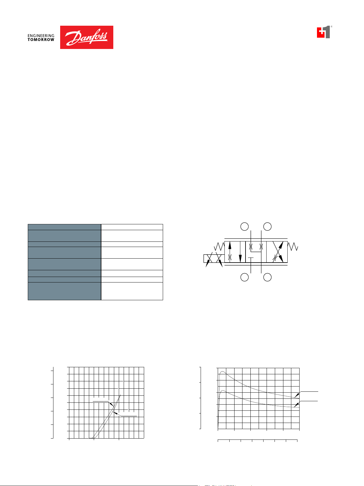
SPECIFICATIONS
CP518-PNC
DIMENSIONS
mm [in]
This valve is a non-compensated, normally-closed, proportional flow control.
Rated pressure 210 bar [3000 psi]
Rated flow at 6 bar
[80 psi]
12 l/min
[3 US gal/min]
Weight 0.36 kg [0.80 lb]
Hysteresis 10% maximum
Threshold current 0.8 A (12 VDC coil)
0.4 A (24 VDC coil)
Maximum control
current
1.8 A (12 VDC coil)
0.9 A (24 VDC coil)
Pressure differential 21 bar [300 psi] maximum
Cavity SDC08-2
Standard Coil M19P 22 Watt
Coil nut 173802114
SCHEMATIC
Cross-sectional view
THEORETICAL PERFORMANCE
Flow vs. Current
at 5.5 bar [80psi] pressure drop
gal/min l/min
174
145
L/min
gal/min
33 cSt[154 SUS] hyd.oil@38°C [100°F]
14
3.7
3.2
12
2.6
10
2.1
8
1.6
6
1.1
4
0.5
2
0.0
11 6
87
58
29
0
0
barpsi
12
10
8
6
4
2
0
0.4
0.00.2 2.0
33 cSt[154 SUS] hyd.oil@38°C [100°F]
024681012141
0.6 0.8 1.21.0 1.4 1.81.6
Current, Amps (with 12 VDCcoil)
Pressure Drop vs. Flow
At MaximumControlCurrent
4H
6H
8H
6H
4H
2H
8H
8
4.84.23.73.22.62.11.61.00.50
5N·m MAX.
[44lbf·in]
COIL NOT SHOWN FOR CLARITY
INSTALL O-RING AS SHOWN
ORDERING
INFORMATION
Seals
Housing and portsHousing P/N
0=Cartridge only No Housing
4S = AL, #4 SAE CP08-2-4S
6S = AL, #6 SAE CP08-2-6S
2B = AL,1/4 BSP SDC08-2-DG-2B
U= Urethane 120591
BC332375973113en-000101 • February 2020
86.1[3.39]
7/8 HEX
27-34N·m
[20-25 lbf·ft]
Seal kits
3/4-16 UNF
2
Termination
00 = No connector
DE = Deutsch
Voltage
00 = No coil
12 = 12 VDC
24 = 24 VDC
Flow code
2H = 5 l/min [1.3 US gal/min] at 5.5 bar [80 psi]
4H = 9 l/min [2.4 US gal/min]
6H = 11 l/min [2.9 US gal/min]
8H = 13 l/min [3.4 US gal/min]
DN = DIN 43650
FL = Lead wires
AJ = AMP Jr
PV - 27
Page 28

Proportional Valves Technical Information
2
1
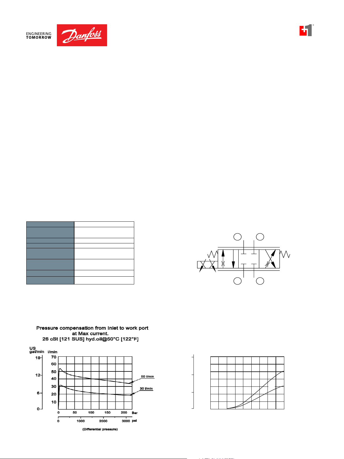
Flow Control, Non-Compensated, Normally Closed
PSV10-NC
OPERATION
SPECIFICATIONS
This is a normally-closed, direct-acting, spool-type, non-compensated, proportional
flow-control. Controlled flow is from port 1 to 2.
Rated pressure 260 bar [3770 psi]
Maximum flow at 10 bar
[145 psi pressure drop]
Leakage 420 cm³/min [25.6 in³/min] @
Weight 0.51 kg [1.12 lb]
Hysteresis 5% maximum
Threshold current 0.5 A (12 VDC coil)
Maximum control
current
Cavity SDC10-2
Standard Coil M19P 22 Watt
PSV10-NC-10: 10 l/min
[2.64 US gal/min]
PSV10-NC-25: 25 l/min
[6.6 US gal/min]
PSV10-NC-40: 40 l/min
[10.6 US gal/min]
rated pressure
0.25 A (24 VDC coil)
1.8 A (12 VDC coil)
0.9 A (24 VDC coil)
THEORETICAL PERFORMANCE
SCHEMATIC
DIMENSIONS
mm [in]
ORDERING
INFORMATION
Cross-sectional view
26mm
3-5 Nm [2.2-3.7bf•ft]
COIL NUTKIT P/N 173802188
COIL NOTSHOWN FORCLARITY
86.80
[3.42]
27
45-50Nm[33-37lbf•ft]
2
32.00
[1.26]
1
354004019
354003419
7/8-14 UNF2A
[Ø1.04]
Ø26.50
BC332375973113en-000101 • February 2020
* PB (Push-Button)
available upon request
Page 29

Proportional Valves Technical Information
Operating Curves
01
2
1
Flow Control, Non-Compensated, Normally Closed
PSV12-NC
OPERATION
SPECIFICATIONS
PSV12-NC
This is a normally-closed, direct-acting, spool-type, non-compensated, proportional
flow-control. Controlled flow is from port 1 to 2.
Rated pressure 260 bar {3770 psi]
Maximum flow at 10 bar
[145 psi]
PSV12-NC-60: 60 l/min
[15.85 US gal/min]
PSV12-NC-80: 80 l/min
[21.13 US gal/min]
Leakage 420 cm³/min [25.6 in³/min] @
rated pressure
Weight 0.76 kg [1.68 lb]
Hysteresis 5% maximum
Threshold current 0.5 A (12 VDC coil)
0.25 A (24 VDC coil)
Maximum control
current
1.8 A (12 VDC coil)
0.9 A (24 VDC coil)
Cavity SDC12-2
Standard Coil D14E(35W) 35 Watt
SCHEMATIC
THEORETICAL PERFORMANCE
US
gal/min
(using a circuit with a pressure drop of 10 Bar)
26 cSt [121 SUS] hyd.oil@50°C [122°F]
l/min
24
80
14
60
12
40
6
20
0
0 0.3 0.9 (A)
(24 V)
(12 V)
0 0.6
Pressure drop (from port 1 to 2)
psi
217
145
72
0
26 cSt [121 SUS] hyd.oil@50°C [122°F]
Bar
15
10
5
0
3020100
40
80
0.6
1.2
60
60
1.8 (A)
80
70
6050
8612
l/min
90
80
US
gal/min
24
DIMENSIONS
mm [in]
ORDERING
INFORMATION
Cross-sectional view
9-11 Nm [6-8 lbf*ft]
Coil NutP/N 17380531
COIL NOTSHOWN FORCLARITY
94.50
[3.72]
32mm27mm
68-75Nm[50-55lbf*ft]
1-1/16-12 UN
2
45.00
[1.77]
1
[Ø1.24]
Ø31.50
BC332375973113en-000101 • February 2020
PV - 29
Page 30

Proportional Valves Technical Information
12
l/min.
2
1
Flow Control, Non-Compensated, Normally Closed
PSV16-NC
OPERATION
SPECIFICATIONS
This is a normally-closed, direct-acting, spool-type, non-compensated, proportional
flow-control. Controlled flow is from port 1 to 2.
Rated pressure 260 bar [3770 psi]
Rated flow at 10 bar
[145 psi]
100 l/min
[26 US gal/min]
Leakage 420 cm³/min [25.6 in³/min] @
rated pressure
Weight 0.87 kg [1.92 lb]
Hysteresis 5% maximum
Threshold current 0.5 A (12 VDC coil)
0.25 A (24 VDC coil)
Maximum control
current
1.8 A (12 VDC coil)
0.9 A (24 VDC coil)
Cavity SDC16-2
Standard Coil D14E(35W) 35 Watt
SCHEMATIC
THEORETICAL PERFORMANCE
US
gal/min
24
20
16
12
8
4
0
(24 V)
(12 V)
0
80
40
Operatingcurve smad ewithcircuit
having apressure drop of 10 bar.
l/min
26 cSt[121SUS]hyd.oil@50°C[122°F]
100
80
60
40
20
0
0
barpsi
26 cSt [121SUS]hyd.oil at 50°C [122°F]
9
6
3
0.60
Pre ssure drop
1.2
0.9(A)0.60.3
1.8 (A)
0
0
DIMENSIONS
mm [in]
27mm
9-11 Nm [6-8 lbf*ft]
Cross-sectional view
38mm
122-136Nm[90-100 lbf*ft]
Coil NutP/N 17380531
COIL NOTSHOWN FORCLARITY
97.30
[3.83]
3.60
[0.14]
15/16-12UN
2
47.10
[1.85]
0
0
4020
1
[Ø1.49]
Ø37.80
100
8060
2010US gal/min
ORDERING
INFORMATION
BC332375973113en-000101 • February 2020
Page 31

Proportional Valves Technical Information
30
20
40
80
60
1
2
Flow Control, Non-Compensated, Normally Closed, Poppet
PSVP10-NCR
OPERATION
SPECIFICATIONS
DIMENSIONS
mm [in]
This is a non-compensated, normally-closed, pilot-operated, poppet-type, proportional
flow-control. Controlled flow is from port 2 to 1.
THEORETICAL PERFORMANCE
Rated pressure 260 bar [3770 psi]
Rated flow at 10 bar
[150 psi]
55 l/min
[14 US gal/min]
Leakage 6 drops/min @
rated pressure
Weight 0.54 kg [1.19 lb]
Hysteresis 8% maximum
Threshold current 0.8 A (12 VDC coil)
0.4 A (24 VDC coil)
Maximum control
current
1.8 A (12 VDC coil)
0.9 A (24 VDC coil)
Cavity SDC10-2
Standard Coil M19P 22 Watt
US
gal/min
30
25
20
15
10
5
0
(24 V)
(12 V)
0
l/min
125
100
75
50
25
0
barpsi
26 cSt[121SUS]hyd.oil at 50°C [122 °F]
60
OperatingC
26 cSt[121SUS]hyd.oil@50°C[122°F]
0
00.6 1.8(A)
Pressuredrop
ur
ves
0.
1.2
0.6
.9 (A)
50 bar
35 bar
20 bar
SCHEMATIC
40
0
0
20
0
0
0
0
0
40
5
10
8060
15
20
100
25
12020
l/min.
US gal/min
Cross-sectional view
26mm
3-5 Nm [2.2-3.7bf*ft]
COIL NUTKIT P/N 173802188
COIL NOTSHOWN FORCLARITY
107.12
[4.22]
27
45-50Nm[33-37lbf*ft]
2
31.90
[1.26]
1
7/8-14 UNF2A
[Ø1.04]
Ø26.50
ORDERING
INFORMATION
BC332375973113en-000101 • February 2020
PV - 31
Page 32

Proportional Valves Technical Information
l/min.
60
80
40
20
1
2
Flow Control, Non-Compensated, Normally Closed,
PSVP12-NCR
OPERATION
SPECIFICATIONS
DIMENSIONS
mm [in]
This is a non-compensated, normally-closed, pilot-operated, poppet-type, proportional
flow-control. Controlled flow is from port 2 to 1.
THEORETICAL PERFORMANCE
Rated pressure 260 bar [3770 psi]
Rated flow at 10 bar
[150 psi]
70 l/min
[18 US gal/min]
Leakage 6 drops/min @
rated pressure
Weight 0.60 kg [1.32 lb]
Hysteresis 8% maximum
Cavity SDC12-2
Standard Coil M19P 22 Watt
SCHEMATIC
US
gal/min
36
30
24
18
12
6
0
(24 V)
(12 V)
psibar
0
0
0
0
0
l/min
150
120
90
60
30
0
0
26 cSt[121SUS]hyd.oil at 50°C [122°F]
60
40
20
0
0
Operating Curves
26 cSt[121SUS]hyd.oil@50°C[122°F]
125
0.9(A)0.3
1.8(A)0.60
US gal/min
0.6
1.2
Pressuredrop
25 150
50
75 100
15 300
50 bar
35 bar
20 bar
Cross-sectional view
PSVP12-NCR
26mm
3-5Nm[2.2-3.7bf*ft]
COIL NUT KITP/N 173802188
COIL NOT SHOWN FOR CLARITY
105.52
[4.15]
32 mm
68-75Nm[50-55lbf*ft]
45
[1.77]
1-1/16-12 UN
1
Ø31.5
[ 1.24]Ø
2
ORDERING
INFORMATION
BC332375973113en-000101 • February 2020
Page 33

Proportional Valves Technical Information
US
gal/min
Operating
Curve s
20
40
80
60
1
2
Flow Control, Non-Compensated, Normally Closed, Poppet Type
PSVP16-NCR
OPERATION
SPECIFICATIONS
PSVP16-NCR
DIMENSIONS
mm [in]
This is a non-compensated, normally-closed, pilot-operated, poppet-type, proportional
flow-control. Controlled flow is from port 2 to 1.
THEORETICAL PERFORMANCE
Rated pressure 260 bar [3770 psi]
Rated flow at 10 bar
[150 psi]
90 l/min
[24 US gal/min]
Leakage 6 drops/min @
rated pressure
Weight 0.85 kg [1.87 lb]
Hysteresis 8% maximum
Cavity SDC16-2
Standard Coil M19P 22 Watt
52
40
32
24
16
(24 V)
(12 V)
0
l/min
26 cSt[121SUS]hyd.oil@50°C[122°F]
200
160
120
80
40
8
0
0
0
0.3 0.9(A)
00.6 1.8(A)
barpsi
60
Pressure drop
26 cSt[121SUS]hyd.oil at 50°C [122 °F]
0.6
1.2
50 bar
35 bar
20 bar
SCHEMATIC
40
0
0
20
0
0
0
20040
160
120
0
0
80
20
40
l/min.
US gal/min
Cross-sectional view
26mm
3-5 Nm [2.2-3.7bf*ft]
COIL NUTKIT P/N 173802188
COIL NOTSHOWN FORCLARITY
ORDERING
INFORMATION
BC332375973113en-000101 • February 2020
38mm
122-136Nm[90-100 lbf*ft]
98.51
[3.88]
15/16-12UN
44.7
[1.76]
1
Ø37.8
[Ø1.49]
2
PV - 33
Page 34

Proportional Valves Technical Information
21
gal/mi
Flow vs. Current
2
1
CP518-PNO-U-6S-2H-24-DE
Flow Control, Non-Compensated, Normally Open
CP518-PNO
OPERATION
SPECIFICATIONS
DIMENSIONS
mm [in]
This valve is a non-compensated, normally-open, proportional flow control.
THEORETICAL PERFORMANCE
Rated pressure 210 bar [3000 psi]
Rated flow at 7 bar
[100 psi]
Weight 0.36 kg [0.80 lb]
Hysteresis 4% maximum
Threshold current 0.2 A (12 VDC coil)
Maximum control
current
Pressure
differential
Cavity SDC08-2
Standard Coil M19P 22 Watt
Coil nut 173802114
SCHEMATIC
12.1 l/min
[3.2 US gal/min]
0.1 A (24 VDC coil)
1.2 A (12 VDC coil)
0.6 A (24 VDC coil)
21 bar [300 psi] maximum
nl/min
3.7
3.2
2.6
2.1
1.6
1.1
0.5
0.0
174
145
11 6
87
58
29
0
L/min
US gal/min
at 5.5 bar [80psi] pressure drop
33 cSt[154 SUS] hyd.oil @ 38°C[100° F]
14
12
8H
10
8
6
2H
4
2
0
0.0 0.
0.40.6 0.8 1.01.41.2
Current, Amps(with12VDC coil)
Pressure Drop vs. Flow
barpsi
33 cSt[154 SUS] hyd.oil@38°C[100° F]
12
10
8
6
4
2
0
0 24681012141618
CoilDe-Energized
2H
Cross-sectional view
.6
8H
CP518-PNO
4.84.23.73.22.62.11.61.00.50
5N·m MAX.
[44 lbf·in]
COIL NOT SHOWN FOR CLARITY
INSTALL O-RING AS SHOWN
ORDERING
INFORMATION
Housing and portsHousing P/N
0=Cartridge only No Housing
4S = AL,#4 SAE CP08-2-4S
6S = AL,#6 SAE CP08-2-6S
2B = AL,1/4 BSP SDC08-2-DG-2B
3B = AL, 3/8 BSP SDC08-2-DG-3B
BC332375973113en-000101 • February 2020
7/8 HEX
27-41N·m
[20-30 lbf·ft]
Seals
U= Urethane 120591
Seal kits
27.7 [1.09]86.1[3.39]
Voltage
00 = No coil
12 = 12 VDC
24 = 24 VDC
Flow code
3/4-16 UNF-2A
2
2H
8H
Termination
00 = No connector
DE = Deutsch
DN = DIN 43650
FL = Lead wires
AJ = AMP Jr
Page 35

Proportional Valves Technical Information
Flow Control, Non-Compensated, Normally Open
PSV10-NO
OPERATION
SPECIFICATIONS
This is a normally-open, direct-acting, spool-type, non-compensated, proportional flowcontrol. Controlled flow is from port 1 to 2.
Rated pressure 260 bar [3770 psi]
Maximum flow at 10 bar
[145 psi]
Leakage 420 cm³/min [25.6 in³/min] @
Weight 0.51 kg [1.12 lb]
Hysteresis 5% maximum
Threshold current 0.1 A (12 VDC coil)
Maximum control
current
Cavity SDC10-2
Standard Coil M19P 22 Watt
PSV10-NO-10: 10 l/min
[2.64 US gal/min]
PSV10-NO-25: 25 l/min
[6.6 US gal/min]
PSV10-NO-40: 40 l/min
[10.6 US gal/min]
rated pressure
0.05 A (24 VDC coil)
1.8 A (12 VDC coil)
0.9 A (24 VDC coil)
THEORETICAL PERFORMANCE
SCHEMATIC
2
1
DIMENSIONS
mm [in]
ORDERING
INFORMATION
Cross-sectional view
26mm
3-5 Nm [2.2-3.7bf*ft]
COIL NUTKIT P/N 173802188
COIL NOTSHOWN FORCLARITY
86.80
[3.42]
27
45-50Nm[33-37lbf*ft]
2
32.00
[1.26]
1
7/8-14 UNF2A
[1.04]
26.50
BC332375973113en-000101 • February 2020
PV - 35
Page 36

Proportional Valves Technical Information
Flow Control, Non-Compensated, Normally Open
PSV12-NO
OPERATION
SPECIFICATIONS
This is a normally-open, direct-acting, spool-type, non-compensated, proportional flowcontrol. Controlled flow is from port 1 to 2.
Rated pressure 260 bar [3770 psi]
Maximum flow at 10 bar
[145 psi]
Leakage 420 cm³/min [25.6 in³/min] @
Weight 0.76 kg [1.68 lb]
Hysteresis 5% maximum
Threshold current 0.3 A (12 VDC coil)
Maximum control
current
Cavity SDC12-2
Standard Coil D14E(35W) 35 Watt
PSV12-NO-60: 60 l/min
[15.85 US gal/min]
PSV12-NO-80: 80 l/min
[31.13 US gal/min]
PSV12-NO-100: 100 l/min
[26.41 US gal/min]
rated pressure
0.15 A (24 VDC coil)
1.8 A (12 VDC coil)
0.9 A (24 VDC coil)
THEORETICAL PERFORMANCE
SCHEMATIC
2
DIMENSIONS
mm [in]
ORDERING
INFORMATION
Cross-sectional view
27mm
9-11 Nm [6-8 lbf*ft]
Coil NutP/N 17380531
COIL NOTSHOWN FORCLARITY
94.50
[3.72]
1
32mm
68-75Nm[50-55lbf*ft]
4.00
[0.16]
1-1/16-12 UN
2
45.50
[1.79]
1
[Ø1.24]
Ø31.50
BC332375973113en-000101 • February 2020
Page 37

Proportional Valves Technical Information
Operating curvesmade with circuit
l/min.
US gal/min
10 200
2
1
Flow Control, Non-Compensated, Normally Open
PSV16-NO
OPERATION
SPECIFICATIONS
This is a normally-open, direct-acting, spool-type, non-compensated, proportional flowcontrol. Controlled flow is from port 1 to 2.
THEORETICAL PERFORMANCE
Rated pressure 260 bar [3770 psi]
Rated flow at 10 bar
[145 psi]
Leakage 420 cm³/min [25.6 in³/min]]
Weight 0.87 kg [1.92 lb]
Hysteresis 5% maximum
Threshold current 0.3 A (12 VDC coil)
Maximum control
current
Cavity SDC16-2
Standard Coil D14E(35W) 35 Watt
SCHEMATIC
110 l/min
[29 US gal/min]
@ Rated pressure
0.15 A (24 VDC coil)
1.8 A (12 VDC coil)
0.9 A (24 VDC coil)
US
gal/min
30
25
20
15
10
5
0
(24 V)
(12 V)
psibar
120
80
40
havingapressure drop of 10 bar.
l/min
26 cSt[121SUS]hyd.oil@50°C[122°F]
125
100
75
50
25
0
0
0
26 cSt [121SUS]hyd.oil at 50°C [122°F]
9
6
3
0.3
0.6
Pressure drop
0.60.9 (A)
1.2
1.8(A)
DIMENSIONS
mm [in]
ORDERING
INFORMATION
Cross-sectional view
27mm
9-11 Nm [6-8 lbf*ft] 122-136 Nm [90-100 lbf*ft]
COIL NOTSHOWN FORCLARIT Y
38mm
Coil NutP/N 17380531
97.3
[3.83]
3.6
[0.14]
0
0
15/16-12UN
2
47.1
[1.85]
0
20 40
1
37.8
[1.49]
60 80
100
BC332375973113en-000101 • February 2020
PV - 37
Page 38

Proportional Valves Technical Information
20
40
80
60
Operating Curves
02
1
2
Flow Control, Non-Compensated, Normally Open, Poppet Type
PSVP10-NOR
OPERATION
SPECIFICATIONS
DIMENSIONS
mm [in]
This is a non-compensated, normally-open, pilot-operated, poppet-type, proportional
flow-control. Controlled flow is from port 2 to 1.
THEORETICAL PERFORMANCE
Rated pressure 260 bar [3770 psi]
Rated flow at 10 bar
[145 psi]
45 l/min
[12 US gal/min]
Leakage 6 drops/min @
Rated pressure
Weight 0.54 kg [1.19 lb]
Hysteresis 8% maximum
Cavity SDC10-2
Standard Coil M19P 22 Watt
SCHEMATIC
US
gal/min
30
25
20
15
10
5
0
(24 V)
(12 V)
0
0
0
0
0
l/min
26 cSt[121SUS]hyd.oil@50°C[122°F]
125
50 bar
100
75
50
25
0
barpsi
60
40
20
0
0
35 bar
20 bar
0
0.3 0.9(A)
00.6 1.8(A)
Pressure drop
26 cSt[121SUS]hyd.oil at 50°C [122 °F]
40
52015
0.6
1.2
12020
100
8060
510
l/min.
US gal/min
Cross-sectional view
26mm
3-5Nm[2.2-3.7bf*ft]
COIL NUTKIT P/N 173802188
COIL NOTSHOWN FORCLARITY
86.8
[3.42]
27
45-50Nm[33-37lbf*ft]
2
31.9
[1.26]
7/8-14 UNF2A
1
Ø26.5
[Ø1.04]
ORDERING
INFORMATION
BC332375973113en-000101 • February 2020
Page 39

Proportional Valves Technical Information
n.
60
80
40
20
1
2
86.34
[3.4]
44.91
[1.77]
Ø31.44
[Ø1.24]
COIL NOT SHOWN FOR CLARITY
2
1
1-1/16-12 UN
COIL NUT KITP/N 173802188
3-5Nm[2.2-3.7bf*ft]
26mm
68-75Nm[50-55lbf*ft]
32 mm
Flow Control, Non-Compensated, Normally Open, Poppet Type
PSVP12-NOR
OPERATION
SPECIFICATIONS
This is a non-compensated, normally-open, pilot-operated, poppet-type, proportional
flow-control. Controlled flow is from port 2 to 1.
THEORETICAL PERFORMANCE
Rated pressure 260 bar [3770 psi]
Rated flow at 10 bar
[150 psi]
70 l/min
[18 US gal/min]
Leakage 6 drops/min @
Rated pressure
Weight 0.60 kg [1.32 lb]
Hysteresis 8% maximum
Cavity SDC12-2
Standard Coil M19P 22 Watt
SCHEMATIC
US
gal/min
36
30
24
18
12
6
0
(24V)
(12V)
psibar
0
0
0
0
l/min
150
120
35 bar
90
20 bar
60
30
0
0
26 cSt[121SUS]hyd.oil at 50°C [122 °F]
60
40
20
Operating Curves
26 cSt[121SUS]hyd.oil@50°C [122°F]
50 bar
0.6
1.2
Pressure drop
0.9(A)0.3
1.8(A)0.60
0
0
DIMENSIONS
mm [in]
Cross-sectional view
0
50
25 150
75 100
15 300
125
l/mi
US gal/min
ORDERING
INFORMATION
BC332375973113en-000101 • February 2020
PV - 39
Page 40

Proportional Valves Technical Information
30
20
40
80
60
1
2
Flow Control, Non-Compensated, Normally Open, Poppet Type
PSVP16-NOR
OPERATION
SPECIFICATIONS
DIMENSIONS
mm [in]
This is a non-compensated, normally-open, pilot-operated, poppet-type, proportional
flow-control. Controlled flow is from port 2 to 1.
THEORETICAL PERFORMANCE
Rated pressure 260 bar [3770 psi]
Rated flow at 10 bar
[150 psi]
80 l/min
[21 US gal/min]
Leakage 6 drops/min @
Rated pressure
Weight 0.85 kg [1.87 lb]
Hysteresis 8% maximum
Cavity SDC16-2
Standard Coil M19P 22 Watt
SCHEMATIC
US
gal/min
52
40
32
24
16
8
0
(24 V)
(12 V)
0
0
0
0
0
l/min
200
160
35 bar
120
20 bar
80
40
0
barpsi
60
40
20
0
0
0
Operating Curves
26 cSt[121SUS]hyd.oil@50°C[122°F]
50 bar
0
00.6 1.8(A)
26 cSt[121SUS]hyd.oil at 50°C [122 °F]
0.
Pressure drop
80
20
1.2
0.6
.9 (A)
20040
160120
40
l/min.
US gal/min
Cross-sectional view
26mm
3-5 Nm [2.2-3.7bf*ft]
COIL NUTKIT P/N 173802188
COIL NOT SHOWN FOR CLARITY
38mm
122-136 Nm [90-100lbf*f t]
89.3
[3.52]
15/16-12UN
44.8
[1.76]
1
Ø37.8
[Ø1.49]
2
ORDERING
INFORMATION
BC332375973113en-000101 • February 2020
Page 41

Proportional Valves Technical Information
Flow Control, Pressure Compensated, Restrictive Type, Normally Closed
PFC10-RC
OPERATION
SPECIFICATIONS
This is a pressure-compensated, restrictive-type,
normally-closed, spool-type, proportional flow-control.
Controlled flow is from port 1 to 2.
Rated pressure 260 bar [3770 psi]
Maximum Flow at
rated pressure
Leakage 420 cm³/min [25.6 in³/min] @
Weight 0.65 kg [1.43 lb]
Hysteresis 8% maximum
Threshold current 0.5 A (12 VDC coil)
Maximum control
current
Cavity SDC10-2
Standard Coil M19P 22 Watt
PFC10-RC-10: 10 l/min
[2.64 US gal/min]
PFC10-RC-30: 30 l/min
[7.9 US gal/min]
rated pressure
0.25 A (24 VDC coil)
1.8 A (12 VDC coil)
0.9 A (24 VDC coil)
SCHEMATIC
THEORETICAL PERFORMANCE
DIMENSIONS
mm [in]
ORDERING
INFORMATION
Cross-sectional view
BC332375973113en-000101 • February 2020
PV - 41
Page 42

Proportional Valves Technical Information
Flow Control, Pressure Compensated, Restricted Type, Normally Closed
PFC12-RC
OPERATION
SPECIFICATIONS
This is a pressure-compensated, restrictive-type,
normally-closed, spool-type, proportional flowcontrol. Controlled flow is from port 1 to 2.
Rated pressure 260 bar [3770 psi]
Maximum Flow at
rated pressure
Leakage 420 cm³/min [25.6 in³/min] @
Weight 0.77 kg [1.70 lb]
Hysteresis 8% maximum
Threshold current 0.3 A (12 VDC coil)
Maximum control
current
Cavity SDC12-2
Standard Coil D14E(35W) 35 Watt
PFC12-RC-45: 45 l/min
[11.9 US gal/min]
PFC12-RC-65: 65 l/min
[17.17 US gal/min]
rated pressure
0.15 A (14 VDC coil)
1.8 A (12 VDC coil)
0.9 A (14 VDC coil)
SCHEMATIC
THEORETICAL PERFORMANCE
DIMENSIONS
mm [in]
ORDERING
INFORMATION
Cross-sectional view
BC332375973113en-000101 • February 2020
Page 43

Proportional Valves Technical Information
US
Flow Control, Pressure Compensated, Restrictive Type, Normally Closed
PFC16-RC
OPERATION
SPECIFICATIONS
DIMENSIONS
mm [in]
This is a pressure-compensated, restrictive-type, normally-closed, spool-type,
proportional Flow control. Controlled flow is from port 1 to 2.
THEORETICAL PERFORMANCE
Rated pressure 260 bar [3770 psi]
Rated Flow at 260 bar
[3771 psi]
90 l/min
[24 US gal/min]
Leakage 420 cm³/min [25.6 in³/min] @
rated pressure
Weight 0.91 kg [2.01 lb]
Hysteresis 8% maximum
Threshold current 0.4 A (12 VDC coil)
0.2 A (24 VDC coil)
Maximum control
current
1.8 A (12 VDC coil)
0.9 A (24 VDC coil)
Cavity SDC16-2
Standard Coil D14E(35W) 35 Watt
SCHEMATIC
Cross-sectional view
gal/min
24
20
16
12
8
4
0
(24V)
(12V)
US
gal/min
24
20
16
12
8
4
0
Operating curves made with circuit
havingapressure drop of 50 bar.
l/min
26 cSt[121SUS] hyd.oi l@50°C [122°F]
100
80
60
40
20
0
0
0.3 0.60.9 (A)
0.6
0
Pressure compensation from Inlet
to work port at maxcurrent
l/min
26 cSt[121SUS]hyd.oil@50°C [122°F]
100
80
60
40
20
0050 100150 200
1000020003000
(Differentialpressure)
1.2
1.8(A)
250
bar
psi
27mm
9-11 Nm [6-8 lbf*ft]
Coil Nut P/N 17380531
COIL NOT SHOWN FOR CLARITY
38mm
122-136 Nm [90-100 lbf*ft]
99.90
[3.93]
6.40
[0.25]
1 5/16-12UN
2
46.40
[1.83]
1
1.49]
37.80
[
ORDERING
INFORMATION
BC332375973113en-000101 • February 2020
PV - 43
Page 44

Proportional Valves Technical Information
Flow Control, Pressure Compensated, Restrictive Type, Normally Open
PFC10-RO
OPERATION
SPECIFICATIONS
This is a pressure-compensated, restrictive-type, normally-open, spool-type,
proportional flow-control. Controlled flow is from port 1 to 2.
Rated pressure 260 bar [3770 psi]
maximum Flow at
rated pressure
Leakage 420 cm³/min [25.6 in³/min] @
Weight 0.65 kg [1.43 lb]
Hysteresis 8% maximum
Threshold current 0.2 A (12 VDC coil)
Maximum control
current
Cavity SDC10-2
Standard Coil M19P 22 Watt
PFC10-RO-10: 10 l/min
[2.64 US gal/min]
PFC10-RO-30: 30 l/min
[7.9 US gal/min]
rated pressure
0.1 A (24 VDC coil)
1.8 A (12 VDC coil)
0.9 A (24 VDC coil)
THEORETICAL PERFORMANCE
SCHEMATIC
DIMENSIONS
mm [in]
ORDERING
INFORMATION
Cross-sectional view
BC332375973113en-000101 • February 2020
Page 45

Proportional Valves Technical Information
Flow Control, Pressure Compensated, Restrictive Type, Normally Open
PFC12-RO
OPERATION
SPECIFICATIONS
This is a pressure-compensated, restrictivetype, normally-open, spool-type, proportional
flow-control. Controlled flow is from port 1 to 2.
Rated pressure 260 bar [3770 psi]
Maximum Flow at
rated pressure
Leakage 420 cm³/min [25.6 in³/min] @
Weight 0.77 kg [1.70 lb]
Hysteresis 8% maximum
Threshold current 0.42 A (12 VDC coil)
Maximum control
current
Cavity SDC12-2
Standard Coil D14E(35W) 35 Watt
PFC12-RO-45: 45 l/min
[11.9 US gal/min]
PFC12-RO-60: 60 l/min
[15.9 US gal/min]
Rated pressure
0.21 A (24 VDC coil)
1.8 A (12 VDC coil)
0.9 A (24 VDC coil)
SCHEMATIC
THEORETICAL PERFORMANCE
DIMENSIONS
mm [in]
ORDERING
INFORMATION
Cross-sectional view
BC332375973113en-000101 • February 2020
PV - 45
Page 46

Proportional Valves Technical Information
US
gal/mi
Flow Control, Pressure Compensated, Restrictive Type, Normally Open
PFC16-RO
OPERATION
SPECIFICATIONS
DIMENSIONS
mm [in]
This is a pressure-compensated, restrictive-type, normally-open, spool-type,
proportional flow-control. Controlled flow is from port 1 to 2.
THEORETICAL PERFORMANCE
Rated pressure 260 bar [3770 psi]
Rated Flow at 260 bar
[3771 psi]
85 l/min
[22 US gal/min]
Leakage 420 cm³/min [25.6 in³/min] @
Rated pressure
Weight 0.91 kg [2.01 lb]
Hysteresis 8% maximum
Threshold current 0.2 A (12 VDC coil)
0.1 A (24 VDC coil)
Maximum control
current
1.8 A (12 VDC coil)
0.9 A (24 VDC coil)
Cavity SDC16-2
Standard Coil D14E(35W) 35 Watt
SCHEMATIC
Cross-sectional view
US
gal/min
24
20
16
12
8
4
0
(24 V)
(12 V)
24
20
16
12
8
4
0
n
Operating curvesma de with circuit
havingapressure drop of 50 bar.
l/min
26 cSt[121SUS]hyd.oil@50°C[122°F]
100
80
60
40
20
0
0
01.2
Pressure compensation from Inlet
l/min
26 cSt[121SUS]hyd.oil@50°C[122°F]
100
80
60
40
20
0
0
0.3 0.6 0.9(A)
0.6
to work port at maxcurrent
(Differentialpressure)
1.8 (A)
250
20015010050
3000200001000
bar
psi
27mm
9-11 Nm [6-8 lbf*ft]
Coil Nut P/N 17380531
COIL NOTSHOWN FORCLARITY
99.90
[3.93]
ORDERING
INFORMATION
BC332375973113en-000101 • February 2020
38mm
122-136Nm[90-100 lbf*ft]
6.40
[0.25]
15/16-12UN
2
46.40
[1.83]
1
[Ø1.49]
Ø37.80
Page 47

Proportional Valves Technical Information
Flow Control, Pressure Compensated, Priority Type, Normally Closed
PFC10-PC
OPERATION
SPECIFICATIONS
This is a pressure-compensated, priority-type,
normally-closed, spool-type, proportional flowcontrol. Controlled flow is from port 1 to 3, port
2 is bypass.
Rated pressure 260 bar [3770 psi]
Maximum flow at
rated pressure
Leakage 420 cm³/min [25.6 in³/min] @
Weight including
coil
Hysteresis 8% maximum
Threshold current 0.36 A (12 VDC coil)
Maximum control
current
Cavity SDC10-3
Standard Coil M19P 22 Watt
PFC10-PC-10: 10 l/min
[2.64 US gal/min]
PFC10-PC-25: 25 l/min
[6.6 US gal/min]
PFC10-PC-40: 40 l/min
[10.6 US gal/min]
rated pressure
0.62 kg [1.37 lb]
0.18 A (24 VDC coil)
1.8 A (12 VDC coil)
0.9 A (24 VDC coil)
SCHEMATIC
THEORETICAL PERFORMANCE
DIMENSIONS
mm [in]
ORDERING
INFORMATION
Cross-sectional view
BC332375973113en-000101 • February 2020
PV - 47
Page 48

Proportional Valves Technical Information
Flow Control, Pressure Compensated, Priority Type, Normally Closed
PFC12-PC
OPERATION
SPECIFICATIONS
This is a pressure-compensated, prioritytype, normally-closed, spool-type,
proportional flow-control. Controlled flow is
from port 1 to 3, port 2 is bypass.
Rated pressure 260 bar [3770 psi]
Maximum flow at
rated pressure
Leakage 420 cm³/min [25.6 in³/min] @
Weight 0.81 kg [1.79 lb]
Hysteresis 8% maximum
Threshold current 0.5 A (12 VDC coil)
Maximum control
current
Cavity SDC12-3
Standard Coil D14E(35W) 35 Watt
SCHEMATIC
THEORETICAL PERFORMANCE
PFC12-PC-50: 50 l/min
[13.21 US gal/min]
PFC12-PC-65: 65 l/min
[17.17 US gal/min]
rated pressure
0.25 A (24 VDC coil)
1.8 A (12 VDC coil)
0.9 A (24 VDC coil)
DIMENSIONS
mm [in]
ORDERING
INFORMATION
Cross-sectional view
BC332375973113en-000101 • February 2020
Page 49

Proportional Valves Technical Information
US
gal/min
Flow Control, Pressure Compensated, Priority Type, Normally Closed
PFC16-PC
OPERATION
SPECIFICATIONS
This is a pressure-compensated, priority-type, normally-closed, spool-type, proportional
flow-control. Controlled flow is from port 1 to 3, port 2 is bypass.
THEORETICAL PERFORMANCE
Rated pressure 260 bar [3770 psi]
Rated flow at 260 bar
[3771 psi]
Leakage 420 cm³/min [25.6 in³/min] @
Weight 0.97 kg [2.14 lb]
Hysteresis 8% maximum
Threshold current 0.4 A (12 VDC coil)
Maximum control
current
Cavity SDC16-3
Standard Coil D14E(35W) 35 Watt
85 l/min
[22 US gal/min]
rated pressure
0.2 A (24 VDC coil)
1.8 A (12 VDC coil)
0.9 A (24 VDC coil)
US
gal/min
Operatingcurvesmadewithcircuit
havingapressure drop of 50 bar.
26 cSt[121SUS]hyd.oil@50°C[12 2°F]
Pressure compensation from Inlet
26 cSt[121SUS]hyd.oil@50°C[12 2°F]
1.2
to work port
SCHEMATIC
DIMENSIONS
mm [in]
ORDERING
INFORMATION
Cross-sectional view
6.4
[0.25]
bar
psi
4000-4000-3000 30002000
BC332375973113en-000101 • February 2020
PV - 49
Page 50

OPERATION
SPECIFICATIONS
Proportional Valves Technical Information
Flow Control, Pressure Compensated, Priority Type, Normally Open
PFC10-PO
This is a pressure-compensated, priority-type, normallyopen, spool-type, proportional flow-control. Controlled
flow is from port 1 to 3, port 2 is bypass.
Rated pressure 260 bar [3770 psi]
Maximum flow at
rated pressure
Leakage 420 cm³/min [25.6 in³/min] @
Weight including
coil
Hysteresis 8% maximum
Threshold current 0.1 A (12 VDC coil)
Maximum control
current
Cavity SDC10-3
Standard Coil M19P 22 Watt
SCHEMATIC
PFC10-PO-10: 10 l/min [2.64 US gal/min]
PFC10-PO-25: 25 l/min [6.6 US gal/min]
PFC10-PO-35: 35 l/min [9.25 US gal/min]
rated pressure
0.72 kg [1.59 lb]
0.05 A (24 VDC coil)
1.8 A (12 VDC coil)
0.9 A (24 VDC coil)
THEORETICAL PERFORMANCE
DIMENSIONS
mm [in]
ORDERING
INFORMATION
Cross-sectional view
BC332375973113en-000101 • February 2020
Page 51

Proportional Valves Technical Information
Flow Control, Pressure Compensated, Priority Type, Normally Closed
PFC12-PO
OPERATION
SPECIFICATIONS
This is a pressure-compensated, prioritytype, normally-open, spool-type,
proportional flow-control. Controlled flow
is from port 1 to 3, port 2 is bypass.
Rated pressure 260 bar [3770 psi]
maximum flow at
rated pressure
Leakage 420 cm³/min [25.6 in³/min] @
Weight 0.81 kg [1.79 lb]
Hysteresis 8% maximum
Threshold current 0.2 A (12 VDC coil)
Maximum control
current
Cavity SDC12-3
Standard Coil D14E(35W) 35 Watt
PFC12-PO-50: 50 l/min
[13.21 US gal/min]
PFC12-PO-70: 70 l/min
[8.5 US gal/min]
rated pressure
0.1 A (24 VDC coil)
1.8 A (12 VDC coil)
0.9 A (24 VDC coil)
SCHEMATIC
THEORETICAL PERFORMANCE
DIMENSIONS
mm [in]
ORDERING
INFORMATION
Cross-sectional view
BC332375973113en-000101 • February 2020
PV - 51
Page 52

Proportional Valves Technical Information
US
gal/min
Flow Control, Pressure Compensated, Priority Type, Normally Closed
PFC16-PO
OPERATION
SPECIFICATIONS
This is a pressure-compensated, priority-type, normally-open, spool-type, proportional
flow-control. Controlled flow is from port 1 to 3, port 2 is bypass.
THEORETICAL PERFORMANCE
Rated pressure 260 bar [3770 psi]
Rated flow at 260 bar
[3771 psi]
90 l/min
[24 US gal/min]
Leakage 420 cm³/min [25.6 in³/min] @
rated pressure
Weight 0.97 kg [2.14 lb]
Hysteresis 8% maximum
Threshold current 0.1 A (12 VDC coil)
0.05 A (24 VDC coil)
Maximum control
current
1.8 A (12 VDC coil)
0.9 A (24 VDC coil)
Cavity SDC16-3
Standard Coil D14E(35W) 35 Watt
US
gal/min
Operatingcurvesmadewithcircuit
havingapressure drop of 50 bar.
26 cSt[121SUS]hyd.oil@50°C[12 2°F]
1.2
Pressure compensation from Inlet
to work port at maxcurrent
26 cSt[121SUS]hyd.oil@50°C[12 2°F]
SCHEMATIC
DIMENSIONS
mm [in]
ORDERING
INFORMATION
Cross-sectional view
Proportional Flow Control,
Pressure Compensated, Priority Type,
Normally Open, 16 Size Cavity
Code Max Regulated Flow
90 90 l/m
Code Coil Voltage
00 No Coil
12D 12V DC
24D 24V DC
Code Coil Termination
00 No Coil
AJ Amp Junior
DE Deutsch
DN DIN 43650
PFC16-PO -
90
- 12D
- DE - SPS -
Code* Manual Override
Omit Push Pin (Standard)
SPS Screw Style
(Push-Type Valve)
*PB (Push Button) available upon request
B
-2000 2000
- 00
Housings & Ports
00: Cartridge Only
6B: 3/4 BSP, AL
8B: 1 BSP, AL
12S: #12 SAE, AL
16S: #16 SAE, AL
Other Housings available
Code Seal Material Seal kit
B Buna 354008919
V Viton 354009019
bar
psi
Housing P/N
No Housing
SDC16-3-HE-6B
SDC16-3-HE-8B
CP16-3-12S
CP16-3-16S
BC332375973113en-000101 • February 2020
Page 53

Proportional Valves Technical Information
Proportional Flow Divider
PFD10-OD
OPERATION
PDF10-OD: Proportional Flow Divider, 10 Size, Normally Open, Divider
This is a proportional, compensated, normally open, flow dividing, preengineered HIC. When there is no current applied to the coils, the inlet flow
is divided equally between ports A and B. As an example, if inlet flow is 40
LPM, the flow out Ports A and B will divide equally 20 LPM. The performance
curve below shows input flow examples of 40, 20 and 10 LPM. Minimum
inlet flow is 10 LPM (2.6 GPM). The flow ratio between ports A and B will
proportionally vary as current is provided to coils S1 or S2. As current
increases to coil S2, the flow to Port B will proportionally increase, while Port
A decreases, as shown in the graph. Inversely, as current increases to coil S1,
the flow to Port A will proportionally increase, while Port B decreases.
Note that this is not a combiner, the flow only exits Ports A and B. Connect the drain port DR to tank, limiting the
pressure on this port to 50 bar (720 psi).
APPLICATIONS
Proportionally divide the input flow between two motors or hydraulic circuits (like HICs). Circuits that can take
advantage of this pre-engineered HIC include any function where the motors or the HICs continuously require
flow, and you only need to proportionally manage the amount of flow between them. Achieve repeatable, loadindependent flow dividing with the built-in pressure compensator. See performance curve below for compensation
capabilities.
Note: For optimal performance, install with the solenoid valve in the horizontal position, reducing the chance for
Shown with Deutsch Coils
SPECIFICATIONS
Rated Pressure 230 bar [3335 psi]
Maximum Rated Flow
Maximum Pressure in
Port DR
Minimum Inlet Flow 10 l/min [2.6 US gal/min]
Weight including Coil 1.15 kg [2.53 lb]
Coil M16 26 Watts
Coil Voltage 12 V 24 V
Max. Control Current 1.5 Amp 0.75 Amp
Hysteresis < 4%
40 l/min
[10.6 US gal/min]
50 bar
[ 720 psi ]
THEORETICAL PERFORMANCE
SCHEMATIC
BC332375973113en-000101 • February 2020
PV - 53
Page 54

DIMENSIONS
235.3
mm [in]
Proportional Valves Technical Information
Proportional Flow Divider
PFD10-OD
[9.26]
20mm
4-6 Nm [35-53 lbf * in]
Coil Nut Kit P/N 1740031
S1S2
89
105
[4.13]
[3.50]
[4.85]
APPROX 123
EXAMPLE CIRCUITS
Proportionally dividing
flow between two motors
109
[4.29]
n8.5 [0.335]
THRU HOLES 2 PLACES
[0.31]
8
82
[3.23]
Proportionally dividing
flow between two hydraulic
systems (HICs)
ORDERING INFORMATION
BC332375973113en-000101 • February 2020
Page 55

Proportional Valves Technical Information
3000
2000
1000
)1
PPR10-PAC-40-A-12D-DN-B-00
Pressure Reducing/Relieving, Piloted
PPR10-PAC
OPERATION
SPECIFICATIONS
DIMENSIONS
mm [in]
This is a pilot-operated, proportional pressure-reducing/relieving valve. With zero
current applied, the reduced pressure (port 1) is at the valve setting.
THEORETICAL PERFORMANCE
Rated pressure 250 bar (3625 psi]
Rated flow at 7 bar
[100 psi]
18 l/min
[5 US gal/min]
Weight 0.62 kg [1.37 lb]
Hysteresis 10% maximum
Threshold current 0 A (12 VDC coil)
0 A (24 VDC coil)
Maximum control
current
1.4 A (12 VDC coil)
0.7 A (24 VDC coil)
Cavity SDC10-3
Standard Coil M19P 22 Watt
SCHEMATIC
psi
3000
2000
1000
0
(24V)
(12V
psi
0
Reducing pressureVs. Current
26 cSt [121 SUS] hyd.oil@50°C [122°F]
bar
10 l/min [2.6 US gal/min] flow
200
150
100
50
0
0
Reducing Pressure Vs.Flow
bar
26 cSt [121 SUS] hyd.oil@50°C [122°F]
250
200
150
100
50
0010 20 30 40
C
B
A
0.3
0.6
C
B
A
26840
0.6
.2
10
Cross-sectional view
0.9
1.8
l/min
US
gal/min
(A)
ORDERING
INFORMATION
BC332375973113en-000101 • February 2020
26mm
3-5 Nm [2.2-3.7bf*ft]
KIT P/N 173802188
COIL NOT SHOWN FOR CLARITY
113.42
[4.47]
Crack ing pressure
Code = Setting in Bar
Std. setting
40 = 40 bar setting (type A)
100 = 100 bar setting (type B)
200 = 200 bar setting (type C)
Pressure range
A= 20 - 60 bar [290 - 870 psi] Max inlet pressure 150 Bar
B= 70 - 150 bar [1015 - 2175 psi]
C= 160 - 210 bar [2320 - 3045 psi]
Coil voltage
12D=12VDC
24D=24VDC
00=No Coil
27
45-50 Nm [33-37 lbf*ft]
7/8-14 UNF 2A
26.5
[1.04]
46.51
[1.83]
Housing and port s
00 = Cartridge only
6S = Al, #6 SAE
8S = Al, #8 SAE
SE3B = Al, 3/8'' BSP
SE4B = Al, 1/2'' BSP
Other housing available
Coil termination
00 = No coil,nut included
AJ= AMP Junior
DE= Deutsch
DN= DIN 46650
FL= Flying leads(140mm lead length standard)
Housing Nomenclature
No Body
CP10-3-6S
CP10-3-8S
SDC10-3-SE3B
SDC10-3-SE4B
Seals
B = Buna-N
V =Viton
Seal ki t
354004210
354003719
Page 56

Proportional Valves Technical Information
154 SUS (33 cSt) hyd. oil @ 100° F (38° C)
3
1
2
CP558-24-B-4S-150-12D-H
Pressure Reducing, Direct Acting
CP558-24
OPERATION
OPERATION
SPECIFICATIONS
SPECIFICATIONS
This valve is a direct acting, proportional, pressure reducing/relieving valve. With zero
current applied, the reduced pressure (port 1) is at a minimum.
THEORETICAL PERFORMANCE
Rated pressure 34 bar [500 psi]
Rated flow at 7 bar
[100 psi]
4 l/min
[1 US gal/min]
Weight 0.27 kg [0.60 lb]
Hysteresis 10% maximum
Threshold current 0.1 A (12 VDC coil)
0.05 A (24 VDC coil)
Maximum control
current
1 A (12 VDC coil)
0.5 A (24 VDC coil)
Cavity SDC08-3
Standard Coil D08 16 Watt
Coil nut 322399
psi bar
580
508
435
363
290
Press ure
218
145
40
35
30
25
20
15
10
573
0
at 1.0 L/min [0.3 gpm] flow
C
0.2
0.4 0.6 0.811.2
Current, Amps (with 12VDC coil)
0
5
3
=
e
d
o
5
22
=
e
d
o
C
=
e
d
o
C
SCHEMATIC
0
5
1
DIMENSIONS
DIMENSIONS
mm [in]
1
ORDERING
ORDERING
INFORMATION
INFORMATION
Cross-sectional view
ht0.875 in
27-34 N.m
[20-25 lbf.ft]
3/4-16UNF
2
Housing and portsHousing P/N
00 =No Housing No Housing
SE2B = AL,1/4 BSP SDC08-3-SE-2B
SE3B = AL, 3/8 BSP SDC08-3-SE-3B
4S = AL, #4 SAE CP08-3-4S
6S = AL, #6 SAE CP08-3-6S
3
Seals
Seal Kit
B= Buna-N 11016151
V=Viton 120708
26mm
3-5 Nm [26-44 lbf*in]
KIT P/N 11041556
includes nut and O-rings
64.9
[2.56]
Voltage
000 = No coil
12D = 12 VDC coil
24D = 24 VDC coil
Pressure Code
150 = 10.3 bar [150 psi]
225 = 15.5 bar [225 psi]
350 = 24.1 bar [350 psi]
Connector
0= No connector
H= DIN 43650
L= Lead
S= Spade
AJ = Amp Junior
M2 = Metripak 150
Type 1
DE = Deutsch
BC332375973113en-000101 • February 2020
PV - 56
Page 57

Proportional Valves Technical Information
PPR09-POD
OPERATION
Proportional Pressure Reducing / Relieving Valve, Pilot Operated, Normally Open to Drain.
With no current to the coil, the “reduced pressure” (port 3) is connected to drain (port 4), while
blocking the inlet (port 2). As current is increased to the coil, inlet (port 2) is connected to
“reduced pressure” (port 3), proportionally increasing the “reduced pressure” as shown on the
performance curve(s). If the “reduced pressure” exceeds the setting induced by the coil, pressure
is relieved to drain (port 4). This 09 Series valve uses a 10 size cavity with an 08 size tube and coil,
providing an optimal product for high flow and low pressure, while minimizing pressure drop in
the system. This valve was formerly branded as XRP 044.
APPLICATION
Common applications include low-pressure proportional pilot control of clutches or hydraulically
piloting large directional spool valves. Refer to example circuits. Use the optional screen to help
protect the actuator from large particles. Select the robust coil for those extreme environmental
conditions – voltage extremes, high temperature, shock & vibration, chemicals, and/or water
ingression.
THEORETICAL PERFORMANCE
Shown with Standard Coil and Filter
Shown with Robust Coil and Filter
SPECIFICATIONS
Rated pressure 50 bar [725 psi]
Rated flow at 7 bar
[100 psi]
Weight 0.34 kg [0.75 lb]
Hysteresis 6% maximum
Threshold current 0.15 A (12 VDC coil)
Maximum control current 1.2 A (12 VDC coil)
DIMENSIONS
Cavity SDC10-4
Standard Coil M13 20 Watt
Robust Coil R13 16 Watt
25 l/min
[7 US gal/min]
0.08 A (24 VDC coil)
0.6 A (24 VDC coil)
Robust Nut P/N 173800539
No coil O-rings needed.
SCHEMATICS
BC332375973113en-000101 • February 2020
PV - 57
Page 58

DIMENSIONS
Proportional Valves Technical Information
PPR09-POD
mm [in]
EXAMPLE APPLICATION CIRCUITS
Cross-sectional view
ORDERING INFORMATION
BC332375973113en-000101 • February 2020
Page 59

Proportional Valves Technical Information
US
Pressure vs. Current
104.4
[4.11]
27 mm
44-50 Nm
[32-37 lbf ft]
47.6
[1.87]
3
2
1
M22x1.5
26mm
3-5 Nm [26-44 lbf*in]
KIT P/N 173802188
Te
NCS06/3-SE-3/8
NCS06/3-SE-1/2
Pressure Reducing/Relieving, Piloted
XRP 06
OPERATION
SPECIFICATIONS
DIMENSIONS
mm [in]
This is a pilot-operated, proportional pressure reducing/relieving valve. With zero current
applied, the reduced pressure (port 1) is at a minimum.
THEORETICAL PERFORMANCE
Rated pressure 315 bar [4500 psi]
Rated flow at 7 bar
[100 psi]
25 l/min
[7 US gal/min]
Weight 0.55 kg [1.21 lb]
Hysteresis 3% maximum
Threshold current 0 A (12 VDC coil)
0 A (24 VDC coil)
Maximum control
current
1.8 A (12 VDC coil)
0.9 A (24 VDC coil)
Cavity NCS06/3
Standard Coil M19P 22 Watt
SCHEMATIC
bar psi
210
180
150
120
90
60
30
0
87
73
58
44
29
15
0
L/min
gal/min
at 5L/min [1.3 US gal/min] Flow Rate
26 cSt[123 SUS] hyd.oil@50 C[122° F]
3045
2610
2175
1740
1305
870
435
0
0.0 0.2 2.0
barpsi
26 cSt[123 SUS] hyd.oil@50 C[122° F]
6
5
4
3
2
1
0
024681012141618
0.6 0.8 1.21.0 1.4 1.81.6
0.4
Current, Amps (with 12 VDCcoil)
Pressure Drop vs. Flow
210
2to1
150
70
50
25
4.84.23.73.22.62.11.61.00.50
Cross-sectional view
ORDERING
INFORMATION
Setting range
25 = 6-25 bar50[90-360 psi]
= 6-55 bar [90-800 psi]
70 = 5-75 bar [90-1100 psi]
150 = 8-155 bar [120-2200 psi]
210 = 9-210 bar [130-3100 psi]
Voltage
00 = No coil
12D = 12VDC
24D = 24VDC
rmination
00 = No connectorDN
AJ = AMP Jr
DE = Deutsch
BC332375973113en-000101 • February 2020
XRP 06 - 70 - 12D -DE - EN - 00 -V
Housing and portsHousing P/N
00 =No Housing No Housing
= DIN 43650 (ISO 4400)
DN1 = “DN” w/Connector
FL600 = Lead wires
SE6S =AL, #6 SAE NCS06/3-SE-6S
SE8S =AL, #8 SAE NCS06/3-SE-8S
SE3/8 =AL, 3/8 BSP
SE1/2 =AL, 1/2 BSP
Seals
V =Viton
Omit = Buna-N
Seals
230000110
230000070
Manual override
0= P0ush control (Standard)
EN = Screw control
PV - 59
Page 60

Proportional Valves Technical Information
24 mm [0.94]
33-38 Nm
[24-28 ft*lb]
3/4-16 UNF
20 mm [.79]
4-6 Nm
[35-53 lbf*in]
P/N 173800539
COIL NOT SHOWN FOR CLARITY
Optional
Filter
1
2
69.0
[2.72]
26.6
[1.05]
PRV08-DAC-215-C-E-R12D-AS-B-F-S6S
Proportional Relief Valve,
08 Size, Direct Acting, Normally Closed
Seal Option
Housing and Ports
Filter Option
Pressure Setting
Maximum Pressure Option
Coil Voltage
Coil Termination
Adjustment Option
Code
Ports & Material
Body Nomenclature
00 Cartridge Only No Body
4S
#4 SAE, AL
CP08-2-4S
6S
#6 SAE, AL
CP08-2-6S
DG-2B
1/4 BSP, AL
SDC08-2-DG-3B
DG-3B
3/8, BSP, AL
SDC08-2-DG-3B
S4S
#4 SAE, DUCTILE
CP08-2-S4S
S6S
#6 SAE, DUCTILECP08-2-S6S
Code
Material
Seal Kits
B
Buna
11191986
V
Viton
11191987
Code
Option
F
Filter
Omit
No Filter
Description
Code
No Coil, with nut
R00
12 VDC
R12D
24 VDC
R24D
Type
Code
AMP SuperSeal 1.5
AS
Deutsch
DE
Flying Leads
FL
Metri-Pack 150 Type 2
M3
Code
Max Pressure
B
155 Bar (2250 psi)
C
215 Bar (3120 psi)
Code
Adjustment Option
E
External
Option
Setting Code (10 bar inc.)
B
65-155 Bar (940-2250 psi)
C
155-215 Bar (2250-3120 psi)
Pressure Relieving, Direct Acting, Normally Closed
PRV08-DAC
OPERATION
SPECIFICATIONS
DIMENSIONS
mm [in]
This is a direct acting, normally closed, proportional pressure relief valve.
Rated pressure 215 bar [3120 psi]
Maximum
recommended flow
155 bar option: 3.78 l/min [1.0 US gal/min]
215 bar option: 2.84 l/min [0.75 US gal/min]
Hysteresis 5% maximum
Threshold current 0 A (12 VDC coil)
0 A (24 VDC coil
Maximum control
current
Standard maximum
setting options
0.8 A (12 VDC coil)
0.4 A (24 VDC coil)
155 bar [2250 psi]
215 bar [3120 psi]
Cavity SDC08-2
Coil R13 16 Watt
Note: A PWM frequency of 50 Hz is recommended for optimal
performance.
SCHEMATIC
Cross-sectional view
THEORETICAL PERFORMANCE
Pressure vs. Current
33 cSt [154 SUS] hyd.oil at 38°C [100 °F]
bar
psi
215
3000
2400
1800
1200
1000
4000
3200
2400
1600
800
600
0
psi
800
600
400
200
0
psi
0
'C' Option
172
129
'B' Option
86
43
0
0.2
Pressure Drop (Maximum Current)
33 cSt [154 SUS] hyd.oil at 38°C [100 °F]
bar
70
56
42
28
14
0
0.8
0
0.2
Pressure Rise (No Current)
33 cSt [154 SUS] hyd.oil at 38°C [100 °F]
bar
280
224
168
112
56
0
0.4
0
0.1
12VDC, R13 coil
1 2
'C' Option
0.4
'C' Option
'B' Option
0.20.4
0.80.60.4
'B' Option
3.22.41.6
0.8
0.61.0
1.61.20.8
0.3
0.5
Current
1.0
Amps
Flow
4.0
L/min
US gal/min
Flow
2.0
US gal/min
L/min
ORDERING
INFORMATION
BC332375973113en-000101 • February 2020
Page 61

Proportional Valves Technical Information
US gal/min
n
Flow
30
Amps
Current
US gal/min
L/min
Flow
1
2
3/4-16 UNF
20 mm [.79]
4-6 Nm
[35-53 lbf*in]
P/N 173800539
COIL NOT SHOWN FOR CLARITY
Optional
Filter
24 mm [0.94]
45-57 Nm
[40-47 ft*lb]
69.0
[2.72]
26.6
[1.05]
Pressure Relieving, Direct Acting, Normally Closed
HPRV08-DAC
OPERATION
SPECIFICATIONS
DIMENSIONS
mm [in]
This is a direct acting, normally closed, proportional pressure relief valve.
THEORETICAL PERFORMANCE
Rated pressure 350 bar [5075 psi]
Maximum
1.89 l/min [0.5 US gal/min]
recommended flow
Hysteresis 5% maximum
Threshold current 0 A (12 VDC coil)
0 A (24 VDC coil
Maximum control
current
Standard maximum
0.8 A (12 VDC coil)
0.4 A (24 VDC coil)
350 bar [5075 psi]
setting
Cavity SDC08-2
Coil R13 16 Watt
Note: A PWM frequency of 50 Hz is recommended
for optimal performance.
SCHEMATIC
Cross-sectional view
5000
4000
3000
2000
1000
500
400
300
200
100
6000
4800
3600
2400
1200
psi
0
psi
psi
0
Pressure vs. Current
33 cSt [154 SUS] hyd.oil at 38°C [100 °F]
bar
350
280
210
140
70
0
0.2
Pressure Drop (Maximum Current)
33 cSt [154 SUS] hyd.oil at 38°C [100 °F]
bar
35
28
21
14
7
0
0
0.4
0
0.1
Pressure Rise (No Current)
33 cSt [154 SUS] hyd.oil at 38°C [100 °F]
bar
420
336
252
168
84
0
0.4
0
0.1
12VDC, R13 coil
0.
0.2
0.3
0.20.4
1 2
1.0
0.80.60.4
1.61.20.8
2.0
L/mi
0.4
.5
2.0
1.61.20.8
0.5
ORDERING
INFORMATION
High Pressure,
Proportional Relief Valve, 08 Size,
Direct Acting, Normally Closed
Pressure Setting
Setting Code (10 bar inc.)
Option
D
215-350 Bar (3120-5075 psi)
Maximum Pressure Option
Code
D
350 Bar (5075 psi)
Adjustment Option
Adjustment Option
Code
E
Max Pressure
External
BC332375973113en-000101 • February 2020
HPRV08-DAC-350-D-E-R12D-DE-B-F -4S
Coil Voltage
DescriptionCode
No Coil, with nut
12 VDC
24 VDC
R00
R12D
R24D
Coil Termination
Type
AMP SuperSeal 1.5
Deutsch
Flying Leads FL
Metri-Pack 150 Type 2
Code
AS
DE
M3
Housing and Ports
Ports & Material
Code
00 Cartridge Only No Body
S4S
#4 SAE, DUCTILECP08-2-S4S
S6S #6 SAE, DUCTILECP08-2-S6S
* Aluminum housings available for use in applications less
than 210 bar (3000 psi). Consult factory for details.
Filter Option
Seal Option
Code
Omit
Code
B
V
F
Body Nomenclature
Option
Filter
No Filter
Material
Seal Kits
Buna
11191986
Viton
11191987
PV - 61
Page 62

Proportional Valves Technical Information
pressure
pressure vs. current
1
2
[3.56]
90.5
[1.06]
26.8
2
1
M18x1.5
22 mm
44-50
Nm
[32-37 lbf ft]
26mm
3-5 Nm [26-44 lbf*in]
KIT P/N 173802188
Pressure Relieving, Direct Acting, Normally Open
XMD 04
OPERATION
SPECIFICATIONS
DIMENSIONS
mm [in]
This is a direct-acting normally-open, proportional relief valve.
THEORETICAL PERFORMANCE
Rated pressure 250 bar [3600 psi]
Rated flow 5 l/min
[1.3 US gal/min]
Weight 0.44 kg [0.97 lb]
Hysteresis 3% maximum
Threshold current 0 A (12 VDC coil)
0 A (24 VDC coil)
Maximum control
current
1.8 A (12 VDC coil)
0.9 A (24 VDC coil)
Cavity NCS04/2
Standard Coil M19P 22 Watt
SCHEMATIC
4000
3500
3000
2500
2000
1500
1000
500
0
psi
175
140
105
pressure
70
35
0
US gal/min
Cross-sectional view
barpsi
26 cSt [125 SUS] hyd.oil @ 20° C [68° F]
270
flow=1 l/min
240
(0.3 US gal/min)
210
180
150
120
90
60
30
0
0 0.6 1.2
Current, Amps (12VDC coil)
0.5
1
0.25
pressure drop
250
2.5
2
1.5
0.5
flow (cap)
coil de-energised
0.75
10.5
7.5
4.5
1.5
bar
12
9
6
3
0
L/min
0
250
150
70
1.8
150
70
5
4.5
3.5
4
3
1
1.25
ORDERING
INFORMATION
BC332375973113en-000101 • February 2020
Page 63

Proportional Valves Technical Information
n
Reverse Free Flow Pressure drop
1000
12
CP558-20-B-6S-300-24D-H
Seals
Seal kit
B=Buna-N 120221
V=Viton 120222
Pressure code
050= 35 bar [500 psi] max
100= 69 bar [1000 psi] max
200= 138 bar [2000 psi] max
300= 207 bar [3000 psi] max
Housing and portsHousing P/N
0=No Housing No Housing
DG2B=AL,1/4 BSP SDC08-2-DG-2B
DG3B=AL, 3/8 BSP SDC08-2-DG-3B
4S = AL, #4 SAE CP08-2-4S
6S = AL, #6 SAE CP08-2-6S
Other housings available
Voltage
000 = No coil
12D = 12 VDC coil
24D = 24 VDC coil
Termination
00 = No connector
H
L = Lead wires
DE = Deutsch
M2 = Metripack 150
Type 1
S = Spade
= DIN 43650
Pressure Relieving, Direct Acting, Normally Open
CP558-20
OPERATION
SPECIFICATIONS
CP558-20
This is a direct-acting normally-open, proportional relief valve.
THEORETICAL PERFORMANCE
Rated pressure 210 bar [3000 psi]
Rated flow 8 l/min
[2 US gal/min]
Weight 0.48 kg [1.06 lb]
Hysteresis 10% maximum
Threshold current 0 A (12 VDC coil)
0 A (24 VDC coil)
Maximum control
current
1.2 A (12 VDC coil)
0.6 A (24 VDC coil)
Cavity SDC08-2
Standard Coil D10 30 Watt
Coil nut 321978
SCHEMATIC
psi bar
3046
2611
2176
1740
1305
870
psi
800
600
400
200
0
154 SUS (33 cSt) hyd. oil @ 100° F (38° C)
210
180
150
120
90
60
Press ure drop
30435
0
0.2
33 cSt [154 SUS] hyd.oil at 38°C [100 °F]
bar
70
56
42
Code 300
28
14
0
0
at 1.0 L/min [0.3 gpm] flow
0
0
0
0
2
3
=
=
e
d
e
o
C
d
o
C
0
5
0
=
de
o
C
0.4 0.6 0.811.2 1.4
Current, Amps (with 12VDC coil)
Code 200
4
1
Code 100
Code 050
Coil de-energized
8
2
16
12
3
4
20
5
Flow
L/min
US gal/mi
DIMENSIONS
mm [in]
1
ORDERING
INFORMATION
BC332375973113en-000101 • February 2020
Cross-sectional view
3/4-16 UNF
2
ht0.875
27-34 N•m
[20-25 lbf•ft]
87.0
[3.43]
26mm
3-5 Nm [26-44 lbf*in]
KIT P/N 11041555
includes nut and O-rings
PV - 63
Page 64

Proportional Valves Technical Information
Setting pressure
pressure vs. current
1
2
The -IS2 uses the M19P-12D-1.1A or M19P-24D-0.55A coil (low power)
The Pressure is set at a higher ow
Relief, Pilot Operated, Normally Closed
PRV10-POC
OPERATION
SPECIFICATIONS
This is a normally-closed, pilot-operated, proportional relief valve.
THEORETICAL PERFORMANCE
Rated pressure 250 bar [3600 psi]
Rated flow 76 l/min
[20 US gal/min]
Weight 0.53 kg [1.17 lb]
Hysteresis 10% maximum
Threshold current 0 A (12 VDC coil)
0 A (24 VDC coil)
Maximum control
current
1.4 A (12 VDC coil)
0.7 A (24 VDC coil)
Cavity SDC10-2
Standard Coil M19P 22 Watt
SCHEMATIC
psi
3000
2000
1000
26 cSt [125 SUS] hyd.oil @ 20° C [68° F]
bar
200
150
50
0
bar
l/min
B
A
12
8
4
0
0
current (amps) 12V coil
100
psi
160
80
US gal/min
C
Pressure drop
1.20.60
1.8
80604020
2501020155
DIMENSIONS
mm [in]
Cross-sectional view
ORDERING
INFORMATION
BC332375973113en-000101 • February 2020
Page 65

Proportional Valves Technical Information
05
1
2
Relief, Pilot Operated, Normally Closed
PRV12-POC
OPERATION
SPECIFICATIONS
DIMENSIONS
mm [in]
This is a normally-closed, pilot-operated, proportional relief valve.
THEORETICAL PERFORMANCE
Rated pressure 250 bar [3600 psi]
Rated flow 180 l/min
[48 US gal/min]
Weight 0.62 kg [1.37 lb]
Hysteresis 10% maximum
Threshold current 0 A (12 VDC coil)
0 A (24 VDC coil)
Maximum control
current
1.5 A (12 VDC coil)
0.8 A (24 VDC coil)
Cavity SDC12-2
Standard Coil M19P 22 Watt
SCHEMATIC
psi
3000
2000
essure
Setting pr
1000
0
bar
200
150
100
50
240
160
pressure vs. current
26 cSt [125 SUS] hyd.oil @ 20° C [68° F]
C
B
A
0
00.6 1.2
current (amps) 12V coil
psi
Bar
16
12
8
80
4
0050 100 150 200
l/min
US gal/min
10 30 4020
Cross-sectional view
1.8
Pressure drop
0
Type E
adjustment
13 mm
7-9 Nm [5-6 lbf*ft]
4mm
Type F and H
adjustment
11.2
[0.44]
MAX
26mm
3-5 Nm [26-44 lbf*in]
KIT P/N 173802188
COIL NOT SHOWN FOR CLARITY
INSTALL O-RINGAS SHOWN
ORDERING
INFORMATION
BC332375973113en-000101 • February 2020
100.0
[3.94]
32mm
68-75 Nm [50-55 lbf*ft]
7.0
[0.28]
1-1/16-12 UN 2A
45.0
[1.77]
1
2
PV - 65
Page 66

Proportional Valves Technical Information
pressure
Pressure vs. current
Relief, Pilot Operated, Normally Open
XMP 06
OPERATION
SPECIFICATIONS
This is a pilot-operated, normally-open, proportional relief valve.
THEORETICAL PERFORMANCE
Rated pressure 315 bar [4500 psi]
Rated flow 50 l/min
[13 US gal/min]
Weight 0.53 kg [1.17 lb]
Hysteresis 3% maximum
Threshold current 0 A (12 VDC coil)
0 A (24 VDC coil)
Maximum control
current
1.8 A (12 VDC coil)
0.9 A (24 VDC coil)
Cavity NCS06/2
Standard Coil M19P 22 Watt
SCHEMATIC
4000
3500
3000
2500
2000
1500
1000
500
280
140
pressure
psi
0
psi
210
70
0
26 cSt [125 SUS] hyd.oil @ 20° C [68° F]
bar
270
flow = 5 l/min
240
[ 1 US gall/min]
210
180
150
120
90
60
30
0
0
bar
20
15
10
5
0
l/min.
0US gal/min
0.4
0.8 1.2
Current, Amps (12VDC coil)
Pressure drop
20 40
5
1.6
coil de-energized
60 8010 30 50 70
14
9.8
flow
250
150
70
2.0
19.1
DIMENSIONS
mm [in]
Cross-sectional view
26mm
3-5 Nm [26-44 lbf*in]
KIT P/N 173802188
COIL NOT SHOWN FOR CLARITY
INSTALL O-RING AS SHOWN
107.0
[4.21]
27 mm
44-50 Nm
[32-37 lbf ft]
M22x1.5
2
28.0
[1.10]
1
ORDERING
INFORMATION
BC332375973113en-000101 • February 2020
 Loading...