

Page 1
Technical Information
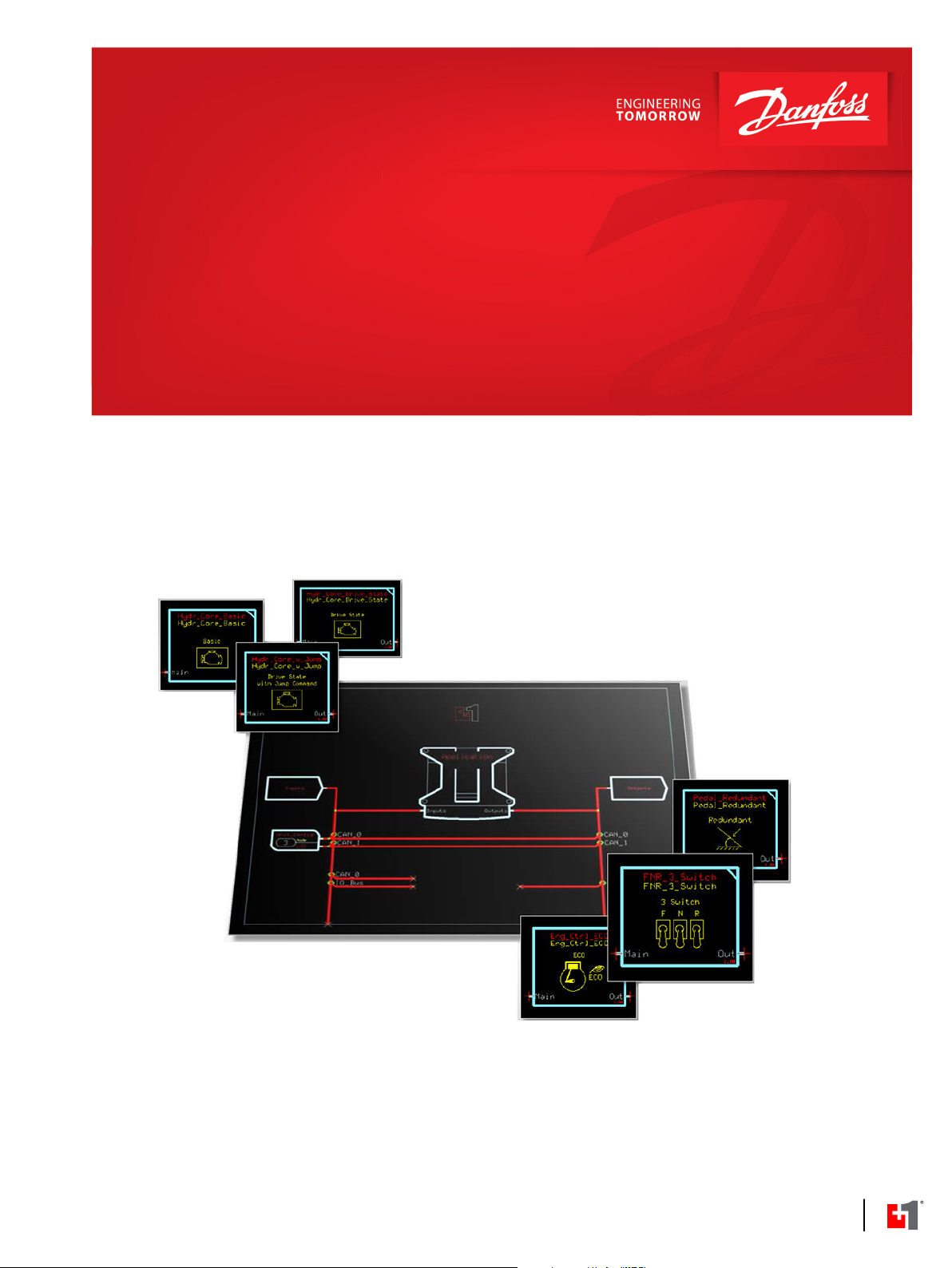
Propel Application Library (PAL)
Software Function Blocks
www.danfoss.com
Page 2
Technical Information
Propel Application Library (PAL) Software Function Blocks
Revision history Table of revisions
Date Changed Rev
June 2019 Correction, removed unreleased function block in PAL Basic and Advanced Function Block
Overview table
March 2019 Removed information regarding a Function block that needs further testing 0301
February 2019 Minor correction 0203
February 2019 Minor correction 0202
February 2019 Added new Function blocks descriptions and drawings 0201
December 2017 First version 0101
0302
2 | © Danfoss | June 2019 BC00000396 | BC262271566298en-000302
Page 3

Technical Information
Propel Application Library (PAL) Software Function Blocks
Contents
Introduction
What is PAL......................................................................................................................................................................................... 4
PAL Basic and Advanced Function Block Overview.............................................................................................................5
Basic Functions
Braking..................................................................................................................................................................................................6
Creeping Automotive..................................................................................................................................................................... 6
Creeping.............................................................................................................................................................................................. 7
Drive Modifier Basic.........................................................................................................................................................................7
Drive State machine with FNR + Hold.......................................................................................................................................8
Engine Control (basic).....................................................................................................................................................................9
Engine Control with Temperature Limitation........................................................................................................................9
FNR 2 Switch.......................................................................................................................................................................................9
FNR 3 Pushbuttons........................................................................................................................................................................10
FNR 3 Switch.................................................................................................................................................................................... 10
FNR 3 pin (LED) Output................................................................................................................................................................11
Hydrostatic Core Basic..................................................................................................................................................................11
Hydrostatic Core Drive State......................................................................................................................................................12
Hydrostatic Core (jump).............................................................................................................................................................. 13
Inching Function............................................................................................................................................................................ 14
Mode Transition Control............................................................................................................................................................. 14
Pedal................................................................................................................................................................................................... 15
Redundant Pedal............................................................................................................................................................................15
Rocker Pedal.................................................................................................................................................................................... 16
Vehicle Speed..................................................................................................................................................................................16
Advanced Functions
Antistall..............................................................................................................................................................................................17
Command Modifier....................................................................................................................................................................... 18
Command Modifier Multiply......................................................................................................................................................19
Cruise Control (basic)....................................................................................................................................................................19
Cruise Control with Jog Up / Down.........................................................................................................................................20
Electronic Pressure Control Override ePCOR.......................................................................................................................20
Electronic Pressure Limiter ePL.................................................................................................................................................21
Engine Control ECO.......................................................................................................................................................................21
Engine Overspeed EOS................................................................................................................................................................ 22
Hydromotor Overspeed Protection.........................................................................................................................................22
Max Hydromotor Torque Control............................................................................................................................................ 23
Stop to Shift..................................................................................................................................................................................... 23
Stop to Shift Driver........................................................................................................................................................................ 24
Temperature Derate......................................................................................................................................................................24
Vehicle Speed Limitation............................................................................................................................................................ 25
Service Tool and Documentation
Braking Function Example..........................................................................................................................................................26
System Builder Sales Tool
PAL Function Blocks Deck of Cards......................................................................................................................................... 28
PAL Function Blocks Card Game.............................................................................................................................................. 29
System Control Visualizer Tool
Graphical Elements Drag and Drop Function......................................................................................................................30
©
Danfoss | June 2019 BC00000396 | BC262271566298en-000302 | 3
Page 4
Technical Information
Propel Application Library (PAL) Software Function Blocks
Introduction
What is PAL
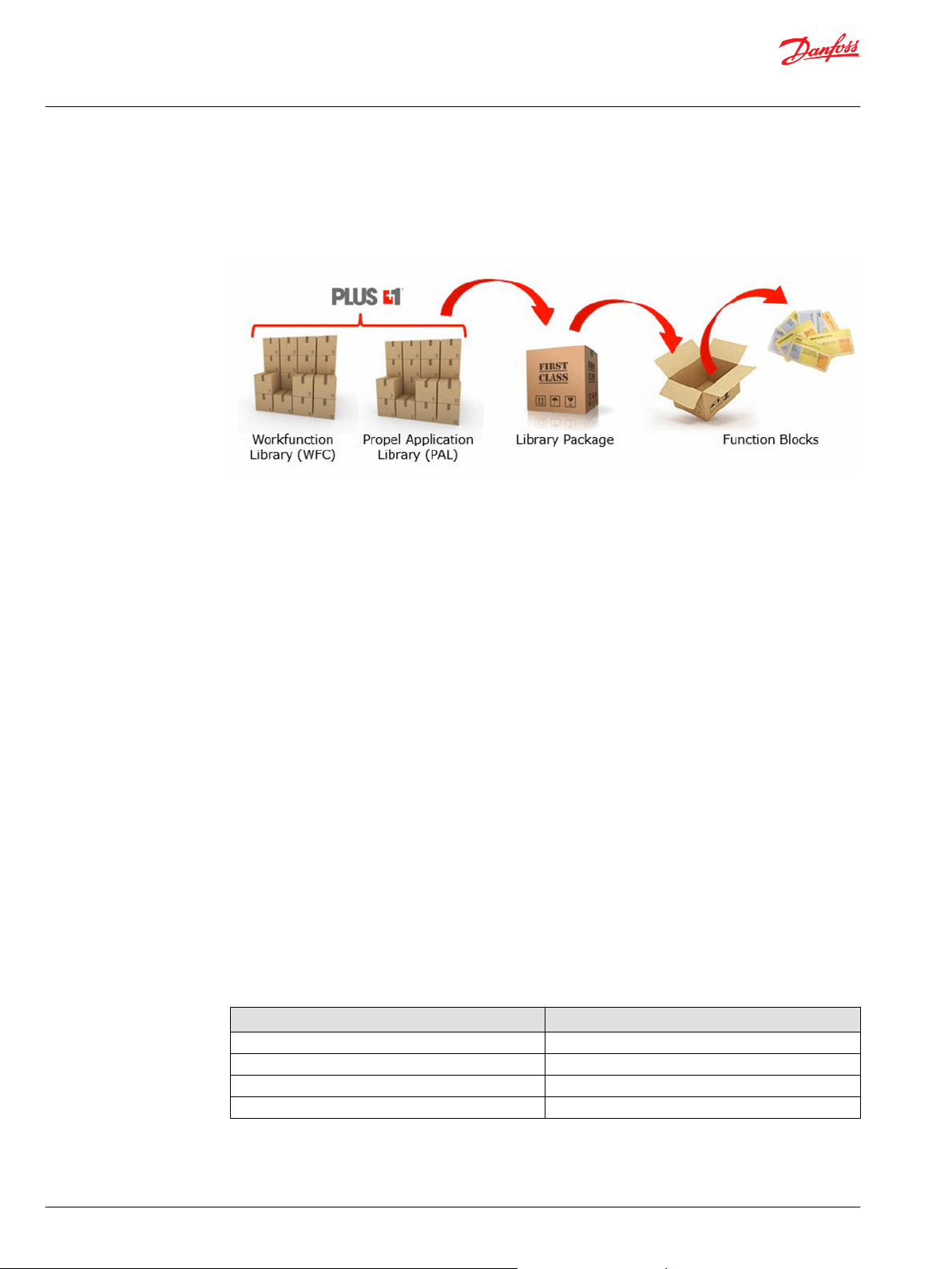
PLUS+1® GUIDE allows to implement different software libraries, such as Work Functions Control (WFC)
and Propel Application Library (PAL). Each library consists of one or more packages which includes
different function blocks.
Use Danfoss PLUS+1® and the library PAL to develop complete propel systems for mobile machinery or
easily integrate any PAL function block into an existing propel system regardless of the system
configuration or hardware in use.
PAL provides a competitive advantage by allowing for superior machine performance, it also dramatically
reduces development time therefore, getting to market faster. The reason for this is that PAL supports the
entire propel software development process, and is aligned with other PLUS+1® compliance blocks.
PAL offers two different library packages. The PAL Basic library package and the PAL Advanced library
package.
The PAL Basic library package offers multiple function blocks to design simple propel solutions; for
instance, one pump and one motor.
The PAL Advanced library package offers function blocks cruise control to get better driving behavior or
Engine Control ECO for fuel saving, which means function blocks for advanced features of propel
solutions. More detail is provided, see Advanced Functions on page 17.
All function blocks of PAL work very well together with PLUS+1® Compliance blocks and other Danfoss
PLUS+1® libraries.
PAL function blocks can be used with all MCxx and SCxx Controllers. Using PAL on application hardware
is not required.
PLUS+1® GUIDE Professional Software (minimum version 8.1 or higher) is required, PAL will not work with
the PLUS+1® GUIDE Express license.
Both PAL library packages can have licenses. The PAL Basic has a free license. The non free licenses are
valid for a limited time and can be renewed by a yearly subscription for each library package.
Each function block of the PAL library package will have the following documents and software files as
part of their scope.
PAL library package
File name File format
PLUS+1® Compliant Software Function Block .scs - PLUS+1® GUIDE
Safety Manual and Programmers Guide .pdf - Adobe PDF
PLUS+1 Service Tool Page .pfx - PLUS+1® Service Tool
User Manual snippet .doc - MS Word
4 | © Danfoss | June 2019 BC00000396 | BC262271566298en-000302
Page 5
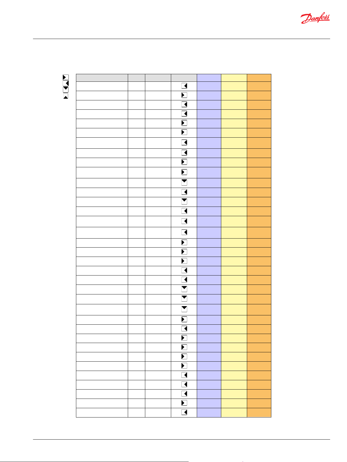
Function Block Basic Advanced FB-Group Input Function Output
Antistall X X
Braking X X
Command Modifier X X
Command Modifier Multiply X X
Creeping X X
Creeping Automotive X X
Cruise Control with jog up/
down
X X
Cruise Control Basic X X
Drive Modifier Basic X X
Drive Statemachine with FNR
+ Hold
X X
Engine Control Basic X X
Engine Control ECO X X
Engine Control Temp Limit X X
Engine Overspeed Protection X X
ePCOR (electronic pressure
control override)
X X
ePL (electronic pressure
limiter)
X X
FNR 2 Switch X X
FNR 3 Pushbutton X X
FNR 3 Switch X X
FNR LED Output X X
Hydro Motor Overspeed X X
Hydrostatic Core Basic X X
Hydrostatic Core Drive State X X
Hydrostatic Core Drive State
with Jump Command
X X
Inching X X
Maximum Motor Torque X X
Mode Transition Control X X
Pedal X X
Pedal Redundant X X
Rocker Pedal X X
Stop to Shift X X
Stop to Shift Driver
X
Temperature Derate X X
X
Vehicle Speed X X
Vehicle Speed Limitation X X
Front Add-on
Rear Add-on
Engine Core
Hydrostatic Core
Technical Information
Propel Application Library (PAL) Software Function Blocks
Introduction
PAL Basic and Advanced Function Block Overview
©
Danfoss | June 2019 BC00000396 | BC262271566298en-000302 | 5
Page 6
Brake Command
Drive Command in
Subtract
& Limit
Drive Command out
Override
Stop Request
Braking
Creeping Automotive
Scale &
Limit
Activation
Engine Speed out
Parameter
Creep Command
Engine Speed in
Technical Information
Propel Application Library (PAL) Software Function Blocks
Basic Functions
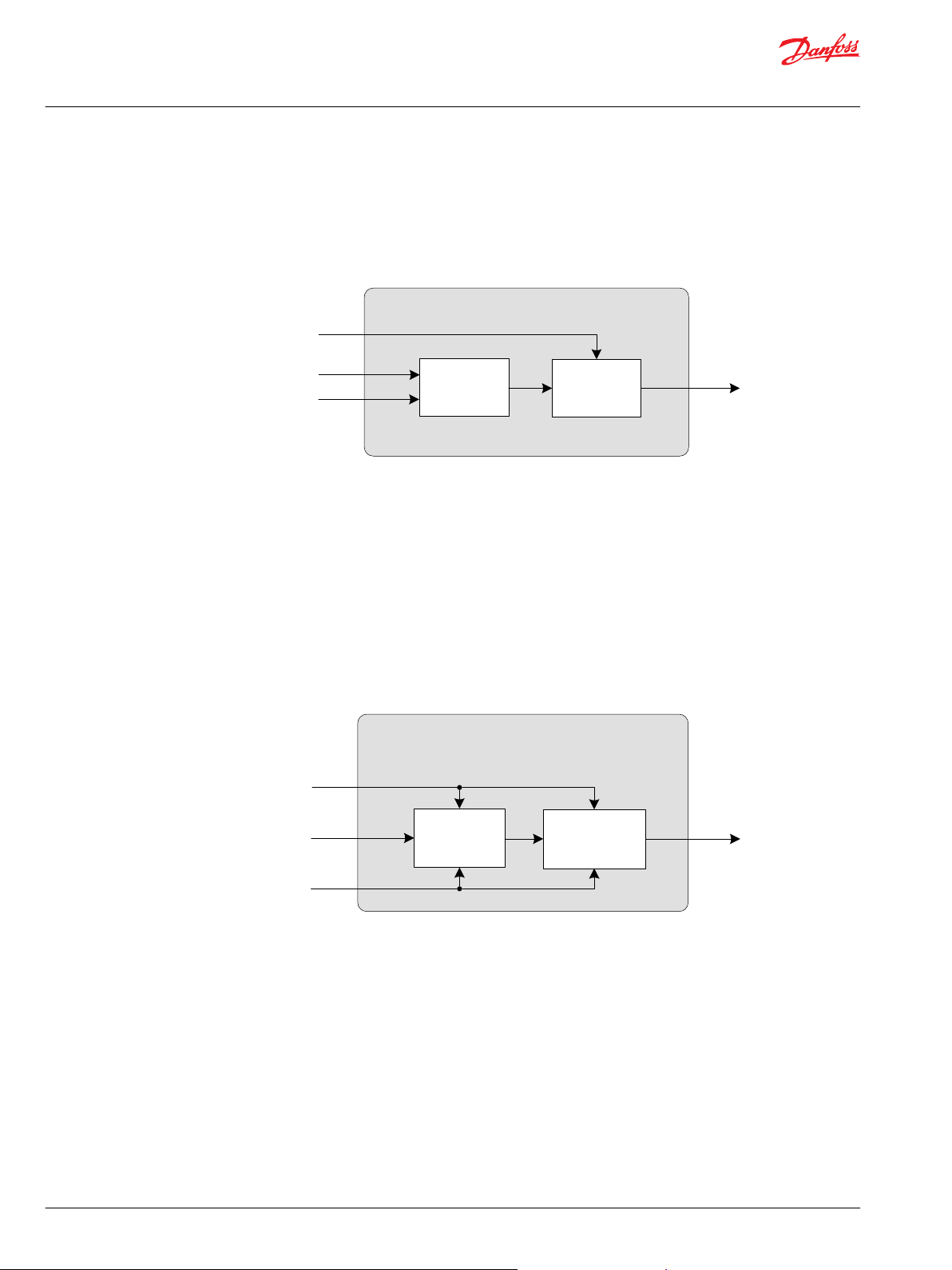
Braking
The Braking function has the purpose of reducing a Drive Command by a Brake Command. Both signals
can be read from a lever, potentiometer or pedal. The function can reduce the Drive Command down to
complete Stop.
The following diagram illustrates in a simplified way how the function block works:
Creeping Automotive
An Automotive drive Mode uses the engine rpm as the setpoint signal for the drive curves. The engine
rpm is measured with a PPU or received via CAN message. This engine rpm signal is virtually reduced by
the Creeping Command, the setpoint for the drive curves is reduced as well.
With a Creeping Command = 100% the Engine Speed In is directly sent to the Engine Speed Out signal.
By parameter a minimum Engine Speed out can be defined. A Creeping Command = 0% will reduce the
Engine Speed in to the minimum Engine Speed out.
This function requires a creeping pedal or potentiometer being installed on the machine. The creeping
signal needs to be prepared as a percentage value (for instance, by using Pedal function block).
The following diagram illustrates in a simplified way how the function block works.
6 | © Danfoss | June 2019 BC00000396 | BC262271566298en-000302
Page 7
Creeping
Multiply
& Limit
Activation
Drv_Cmd_Out
Parameter
Creep_Cmd
Drv_Cmd_In
6-point Profile
Time Ramp
Drv_Cmd_Out
Parameter
Drv_Cmd_In
Drv_Factor
Stop_Rqst
Drive Modifier Basic
Technical Information
Propel Application Library (PAL) Software Function Blocks
Basic Functions
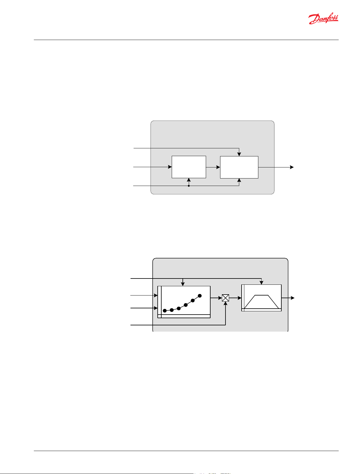
Creeping
Creeping is a function to scale (reduce) the Drive Command In proportionally.
With a Creeping Command = 100% the Drive Command in is equal to the Drive Command out. A
Creeping Command = 0% will reduce the Drive Command out to 0%. This function requires a creeping
pedal or potentiometer being installed on the machine. The creeping signal needs to be prepared as a
percentage value (for instance, by using Pedal function block).
The following diagram illustrates in a simplified way how the function block works.
Drive Modifier Basic
Drive Modifier Basic is a function that modifies an Input Drive Command with a 6-point profile. A
percentage factor is used to modify the output of the profile. If a stop request is received, the Output
Drive Command is pulled to zero. The final output is time-ramped at a rate settable by time rate
parameters.
The following diagram illustrates in a simplified way how the function block works.
©
Danfoss | June 2019 BC00000396 | BC262271566298en-000302 | 7
Page 8
Stop
Forward
Forward
Braking
Forward
Reversal
Reverse
Braking
Reverse
Reversal
Reverse
Hold Direction
Start Protection
Direction Request
Drive State
Direction State
Stop Request
Drive State Machine with FNR + Hold
Range
Check
Override
State
Machine
Technical Information
Propel Application Library (PAL) Software Function Blocks
Basic Functions
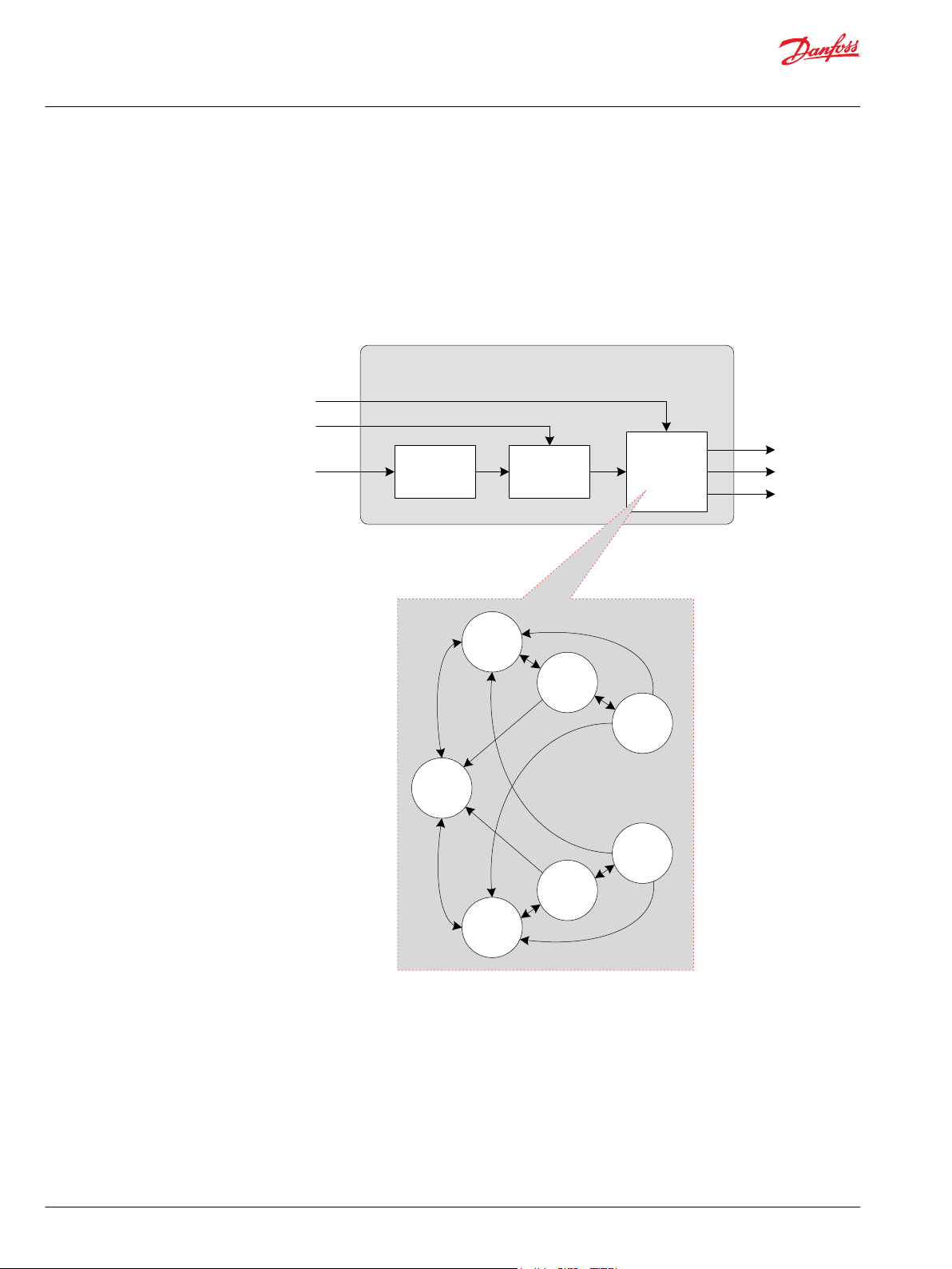
Drive State machine with FNR + Hold
The Drive State Machine is a function between a FNR to choose the driving direction and the hydraulic
power transmission for driving (pump + hydromotor). The Drive State Machine sets the Direction State
based on the request given via Direction Request (FNR). The Start Protection can block the Direction
Request e.g. if the engine rpm is too low.
The function Hold Direction can hold (store) the Direction Request if there is a reason not to change the
driving direction e.g. vehicle speed is too fast for a safe direction change.
The following diagram illustrates in a simplified way how the function block works.
8 | © Danfoss | June 2019 BC00000396 | BC262271566298en-000302
Page 9
Engine Speed Command
Drive Command
Engine Control (basic)
Scale Ramp
Parameter
Scale
Ramp
Parameter
Temperature
Limitation
Limited
Engine Control with
Temperature Limitation
Drive
Command
Temperature
Engine Speed
Command
FNR 2 Switch
Parameter
Forward Input
Reverse Input
Direction
Request
Fault
Detection
Override
FNR
Logic
Technical Information
Propel Application Library (PAL) Software Function Blocks
Basic Functions
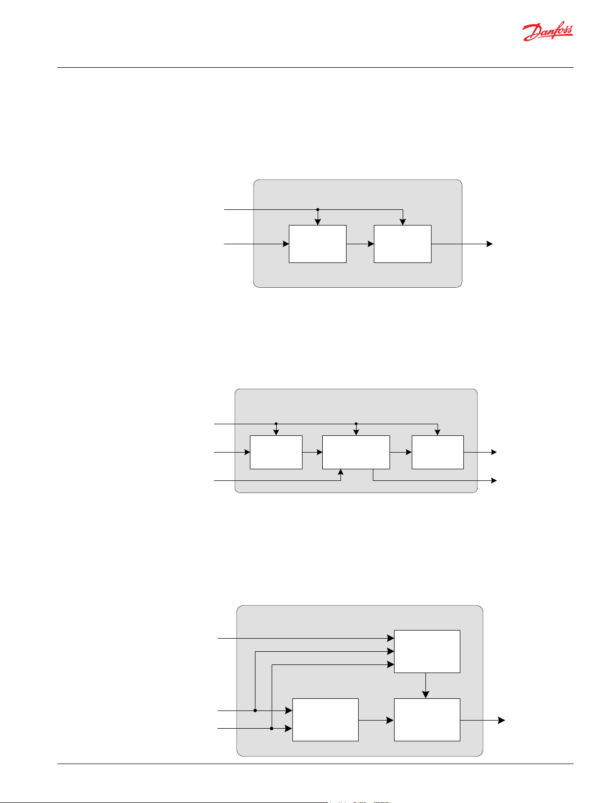
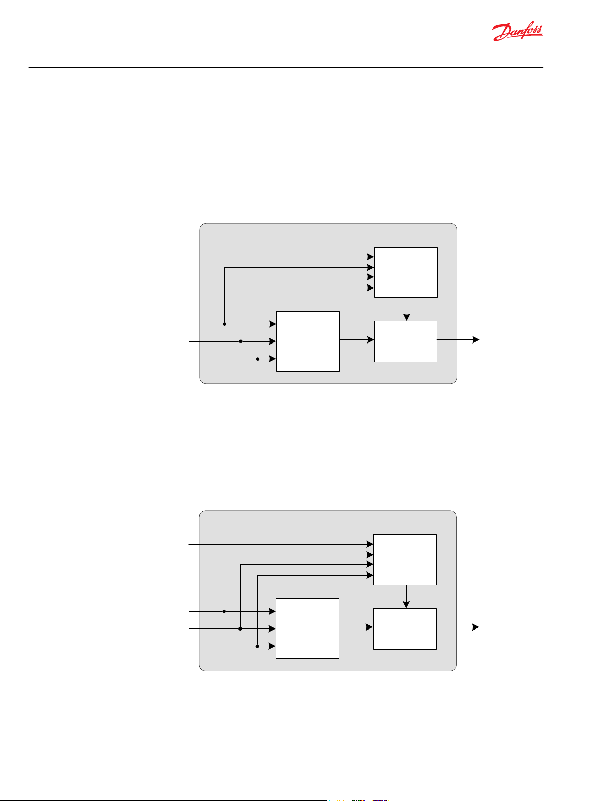
Engine Control (basic)
The Engine Control Basic is a function that converts a Drive Command into an Engine Speed Command
and passes the output command through a time ramp. This requires an interface to the diesel engine
such as a CAN bus or throttle actuator.
The following diagram illustrates in a simplified way how the function block works.
Engine Control with Temperature Limitation
This function converts a Drive Command into an Engine Speed command and passes the output
command through a time ramp. If the measured Temperature is below a threshold value the engine
speed command will be limited to a parameter value and the output Limited will indicate that the engine
speed limitation is active. This function block shall be used for generating an engine speed setpoint. This
requires an interface to the diesel engine such as a CAN bus or throttle actuator.
The following diagram illustrates in a simplified way how the function block works.
FNR 2 Switch
The FNR switch for 2 pushbuttons function block generates a Driving Direction request (Forward, Neutral
or Reverse) based on Forward Switch and Reverse Switch. If Forward Switch is active exclusively, the
Direction Request will be Forward. If Reverse Switch is active exclusively, the Direction Request will be
Reverse. If no switch is active, the Direction Request will be Neutral. If both switches are active for more
than Error Delay Time, a fault will be declared and the Driving Direction request output is forced to
Neutral.
The following diagram illustrates in a simplified way how the function block works.
©
Danfoss | June 2019 BC00000396 | BC262271566298en-000302 | 9
Page 10
FNR 3 Pushbuttons
Forward Input
Reverse Input
Neutral Input
Direction
Request
Parameter
FNR Logic
Override
Fault Detection
FNR 3 Switch
Forward Input
Reverse Input
Neutral Input
Direction RequestFNR Logic Override
Fault Detection
Parameter
Technical Information
Propel Application Library (PAL) Software Function Blocks
Basic Functions
FNR 3 Pushbuttons
The FNR switch for 3 pushbuttons function block generates a Driving Direction request (Forward, Neutral
or Reverse) based on Forward Pushbutton, Reverse Pushbutton and Neutral Pushbutton. If Forward
Pushbutton is active exclusively, the Direction Request will be Forward. If Reverse Pushbutton is active
exclusively, the Direction Request will be Reverse. If Neutral Pushbutton is active exclusively, the
Direction Request will be Neutral. If no Pushbutton is active the last Direction Request will be kept. If
more than one pushbutton is active at the same time for more than Error Delay Time, a fault will be
declared and the Driving Direction request output is forced to Neutral.
The following diagram illustrates in a simplified way how the function block works.
FNR 3 Switch
The FNR switch for 3 state switch function block generates a Driving Direction request (Forward, Neutral
or Reverse) based on three input signals. The signal must be held (continuously). If Forward Switch is
active exclusively, the Direction Request will be Forward. If Reverse Switch is active exclusively, the
Direction Request will be Reverse. If Neutral Switch is active exclusively, the Direction Request will be
Neutral. If none or more than one switch is active for more than Error Delay Time, a fault will be declared
and the Driving Direction request output is forced to Neutral.
The following diagram illustrates in a simplified way how the function block works.
10 | © Danfoss | June 2019 BC00000396 | BC262271566298en-000302
Page 11

Limit
Decode
Direction
Request
Output Forward
Output Neutral
Output Reverse
FNR 3 pin (LED) Output
Parameter
Error
Drive Command
Hydrostatic
Command
Hydrostatic Core Basic
Profile Ramp
Technical Information
Propel Application Library (PAL) Software Function Blocks
Basic Functions
FNR 3 pin (LED) Output
This FNR LED Output block derives three output signals Forward, Reverse and Neutral from the input
Driving Direction. It can be used to control direction indication lamps.
The following diagram illustrates in a simplified way how the function block works.
Hydrostatic Core Basic
This function block takes an input Drive Command and converts it into a Hydrostatic Command. It allows
implementing different drive concepts for pump and motor such as Automotive Control and NonAutomotive Control. The Drive Command can be from various signals. For Automotive Control the drive
command will be the engine speed. For implementing a Non-Automotive Control the drive command
can be a pedal position or a hydrostatic ratio command. There’s no specific hardware for this function
block required. It is recommended that the engine goes to Low Idle instead of High Idle in case of an
error (such as, a lost connection).
The following diagram illustrates in a simplified way how the function block works.
©
Danfoss | June 2019 BC00000396 | BC262271566298en-000302 | 11
Page 12

Parameter
Profile
Error
Ramp
Parameter
Selector
Force
To Zero
Drive State
Drive Command
Hydrostatic
Command
Hydrostatic Core Drive State
Technical Information
Propel Application Library (PAL) Software Function Blocks
Basic Functions
Hydrostatic Core Drive State
This function block takes an input Drive Command and converts it into a Hydrostatic Command. It allows
implementing different drive concepts for pump and motor such as Automotive Control and NonAutomotive Control. The drive command can be from various signals. For Automotive Control the drive
command will be the engine speed. For implementing a Non-Automotive Control the drive command
can be a pedal position or a hydrostatic ratio command.
Different sets of parameters are used for internal profile and time ramp depending on the actual drive
state. The input drive command is automatically forced to zero when the Drive State is at Braking,
Reversal, Stop, Parking or an undefined state. So only when drive state is Forward or Reverse the drive
command will be forwarded to the corresponding profile. There’s no specific hardware for this function
block required. It is recommended that the engine goes to Low Idle instead of High Idle in case of an
error (e.g. lost connection).
The following diagram illustrates in a simplified way how the function block works.
12 | © Danfoss | June 2019 BC00000396 | BC262271566298en-000302
Page 13

Parameter
Profile
Error
Ramp
Parameter
Selector
Jump
Function
Force
To Zero
Drive State
Drive Command
Hydrostatic
Command
Hydrostatic Core (jump)
Technical Information
Propel Application Library (PAL) Software Function Blocks
Basic Functions
Hydrostatic Core (jump)
This function block is intended to be used for controlling NFPE pumps.
This function block takes an input Drive Command and converts it into a hydrostatic command. It allows
implementing different drive concepts for pumps such as Automotive Control and Non-Automotive
Control. The drive command can be from various signals. For Automotive Control the drive command will
be the engine speed. For implementing a Non-Automotive Control the drive command can be a pedal
position or a hydrostatic ratio command.
Different sets of parameters are used for internal profile and time ramp depending on the actual drive
state. The input Drive Command is automatically forced to zero when the Drive State is at Braking,
Reversal, Stop, Parking or an undefined state. Only when drive state is Forward or Reverse the Drive
Command will be forwarded to the corresponding profile.
In this kind of hydrostatic core function block it is possible to perform a jump of the hydrostatic
command. The jump feature is useful when implementing an Automotive Control using a NFPE pump.
Typically the current controlling a NFPE pump is overdriven to ensure that the pump is at maximum
displacement. When triggering a Reversal, Braking or Stop state the pump current will ramp down, but
without any vehicle deceleration as long as the pump current is above a machine specific threshold. The
jump feature allows skipping this current range by jumping directly to this threshold. There’s no specific
hardware for this function block required. It is recommended that the engine goes to Low Idle instead of
High Idle in case of an error (e.g. lost connection).
The following diagram illustrates in a simplified way how the function block works.
©
Danfoss | June 2019 BC00000396 | BC262271566298en-000302 | 13
Page 14

Inching
Profile
Multiply
& Limit
Activation
Drive
command out
Drive Command in
Inch Command
Parameter
Encode
ModeIntlk_1
ModeIntlk_15
ModeIntlkMand
.
.
.
.
.
&&&&&&
Select
Parameter
Mode_Rqst
Init_Mode
Parameter
ModeIntlkMsk
Mode
Select
Init Mode
Mode_Actual
Mode_Pend
a
b
a = b
a
b
a = b
0
(bitwis e)
(U16)
Mode Transition Control
Technical Information
Propel Application Library (PAL) Software Function Blocks
Basic Functions
Inching Function
The Inching signal reduces the drive command. A 0% Inch Signal leaves the drive command unchanged
(Drive Command in = Drive Command out). A 100% Inch signal reduces the Drive Command out to 0. The
Inch Command can be profiled by an 8 point profile.
The following diagram illustrates in a simplified way how the function block works.
Mode Transition Control
The Mode Transition Control function block checks whether a requested mode change can be performed
or not. For each possible mode change, one parameter is available to select which of 15 Mode Interlock
condition inputs must be checked. Mode Interlock condition inputs must be 0 (False) for a mode change.
The Mode Interlock mandatory input will block any mode change as long as it is 1 (True), this mode
change is not de-selectable.
The following diagram illustrates in a simplified way how the function block works.
14 | © Danfoss | June 2019 BC00000396 | BC262271566298en-000302
Page 15

Pedal
Nominal Signal
Supply Voltage
Pedal
Command
Parameter
Pressed
Linear Scale Calibration Override
Pedal Status
Fault
Detection
Redundant Pedal
Parameter
Redundant
Signal
Nominal Signal
Supply Voltage
Redundancy
Check
Linear
Scale
Calibration Override
Fault
Detection
Pedal
Status
Pedal
Command
Pressed
Technical Information
Propel Application Library (PAL) Software Function Blocks
Basic Functions
Pedal
The Pedal function block converts a voltage signal from a pedal into a percentage output. This
percentage output is based on the signal characteristics of the sensor. A built-in calibration routine can
capture the electric signal at each end of the sensors range. This function block scales its output between
0% and 100%.
The following diagram illustrates in a simplified way how the function block works.
Redundant Pedal
The Redundant Pedal function block converts a voltage signal from a pedal into a percentage output.
This percentage output is based on the signal characteristics of the sensor. A built-in calibration routine
can capture the electric signal at each end of the sensor’s range. This function block scales its output
between 0% and 100%. It also uses a redundant pedal signal input to monitor if the nominal signal works
well.
The following diagram illustrates in a simplified way how the function block works.
©
Danfoss | June 2019 BC00000396 | BC262271566298en-000302 | 15
Page 16

Nom_Signal
Supply
Linear
Scale
Fault
Detection
Override Pedal_Cmd
Parameter
Calibration
Safe_Cmd
Pedal
Status
Pressed
Redundancy
Check
Red_Signal
Direction
Detection
Dir_Rqst
Rocker Pedal
Vehicle Speed
Scaling Veh_SpdHydr_Motor_Spd
Parameter
Technical Information
Propel Application Library (PAL) Software Function Blocks
Basic Functions
Rocker Pedal
A Rocker Pedal is quite similar to an analog joystick with spring controlled center position. In the center
position the pedal voltage is at about 50% of supply voltage. In the max forward position, the pedal
voltage is at about 90% of supply voltage. In the max reverse position, the pedal voltage is at about 10%
of supply voltage.
The Rocker Pedal block converts a raw signal from the Rocker Pedal sensor into a percentage output. This
percentage output is based on the signal characteristics of the sensor. A built-in calibration routine can
capture the electrical signal at each end of the sensor’s range and at the center position. The block scales
its output between 0% and +100%. Additionally, the block outputs a direction request signal, like a FNR
(Forward, Neutral, Reverse), based on the pedal voltage signal. The block also uses a redundant pedal
signal to monitor if the nominal signal works well.
Vehicle Speed
The Vehicle Speed function block takes an input of Hydro Motor Speed and outputs the Vehicle Speed
per physical dimensions (wheel circumference, axle ratio and gearbox ratio).
The following diagram illustrates in a simplified way how the function block works.
16 | © Danfoss | June 2019 BC00000396 | BC262271566298en-000302
Page 17

Parameter
Antistall
Scaling
PI
Controller
Active
AS_Adj
Eng_Spd_Cmd
Eng_Spd/Load
Eng_Scale
PI_Scale
Enable_B
Hold
Technical Information
Propel Application Library (PAL) Software Function Blocks
Advanced Functions
Antistall
The Antistall detects engine stalling conditions and generates an appropriate signal to manage power
use by vehicle functions so the engine can recover without stalling while keeping machines functions
operational at a reduced capacity.
Dependent on the setting of the parameter Detect Mode the Antistall function is based on one of two
strategies:
Speed Drop Error calculation
•
Engine Load Error calculation
•
The error signal is used as a loop back signal of the PI controller. The resulting Antistall Adjust signal can
be utilized by Command Modifier block.
The following diagram illustrates in a simplified way how the function block works.
©
Danfoss | June 2019 BC00000396 | BC262271566298en-000302 | 17
Page 18

Ran ge
Che ck and
Limi tation
Apply
Adju st
Valu es
Prio rity
Command Modifier
Priority 1 adjustment
Priority 3 adjustment
Priority 2 adjustment
Priority 4 adjustment
Priority 5 adjustment
Priority 6 adjustment
Priority 7 adjustment
Priority 8 adjustment
Command in
Priority 2 hold
Priority 3 hold
Priority 4 hold
Priority 5 hold
Priority 6 hold
Priority 7 hold
Priority 8 hold
Command adjust
Command out
Technical Information
Propel Application Library (PAL) Software Function Blocks
Advanced Functions
Command Modifier
The Command Modifier function block is used to modify a command signal by adding adjust value. This
could be a different control functions (e.g. Motor Overspeed Protection, Engine Overspeed Protection,
Speed Limiter, Antistall, etc.).
Furthermore the Command Modifier function block calculates a hold signal for each of the control
functions. The hold signals allow to hold the adjust value of a control function with a lower priority at its
momentary value if another control function with a higher priority becomes active (adjust value no
longer zero).
The following diagram illustrates in a simplified way how the function block works.
18 | © Danfoss | June 2019 BC00000396 | BC262271566298en-000302
Page 19

Command Modifier Multiply
Command_In
Prio8_Adjust
Prio7_Adjust
Prio6_Adjust
Prio5_Adjust
Prio4_Adjust
Prio3_Adjust
Prio2_Adjust
Prio1_Adjust
Prio1_LimitMask
Priority
Prio2_Hold
Prio3_Hold
Prio4_Hold
Prio5_Hold
Prio6_Hold
Prio7_Hold
Prio8_Hold
Command_Out
Prio3_LimitMask
Prio2_LimitMask
Prio5_LimitMask
Prio4_LimitMask
Prio7_LimitMask
Prio6_LimitMask
Prio8_LimitMask
Value to
Factor
Calculation
Range is
limited
Apply
Adjust
Factors,
limit to
Command
Range
a
b
a > b
Error
Resume
Enable
Activate
Deactivate
Drive Command In
Control
Logic
Mem
Override
Logic
Drive Command Out
Cruise Control (basic)
Only ramping
the transitions
at deactivation
and resume
Update
Active
Time Ramp
Technical Information
Propel Application Library (PAL) Software Function Blocks
Advanced Functions
Command Modifier Multiply
There may be more than one functions (such as, motor overspeed protection, engine overspeed
protection, ePCOR, …) that need to modify a hydro motor command signal (in terms of displacement) by
applying their adjust values to it. The control functions may have different priority. Therefore, the adjust
value of a control function with a lower priority must be held at its momentary value if another control
function with a higher priority becomes active (adjust value no longer zero). The Prio’n’_Hold outputs
(n=2..8) serve this purpose. The Command Modifier Multiply first converts the adjust values provided by
up to eight control functions into adjust factors which are then applied sequentially onto a hydro motor
command signal, beginning with the lowest priority adjust factor. The Prio’n’_LimitMask outputs (n=1..8)
indicate that by applying Prio’n’_Adjust_Factor the modified hydro motor command signal has reached
the upper or the lower limit (can be used to avoid winding up of the corresponding control function).
The following diagram illustrates in a simplified way how the function block works.
Cruise Control (basic)
The Cruise Control function stores (freeze) the Drive Command value (vehicle speed) when activated. The
cruise operation can be deactivated and resumed.
The following diagram illustrates in a simplified way how the function block works.
©
Danfoss | June 2019 BC00000396 | BC262271566298en-000302 | 19
Page 20

Activation
Logic
Mem
Active
Update
a
b
a > b
Override
Logic
Active
Inc/Dec
Logic
Update
Error
Cruise Control with Jog Up / Down
Drive Command in
Drive Command out
Increase
Decrease
Enable
Activate
Deactivate
Resume
Time Ramp
ePCOR
Scaling
PI
Controller
Parameter
Drive_Pressure
Pressure_Limit
Enable_B
Hold
Active
ePCOR_Adj
Technical Information
Propel Application Library (PAL) Software Function Blocks
Advanced Functions
Cruise Control with Jog Up / Down
The Cruise Control function stores (freeze) the Drive Command value (vehicle speed) when activated. The
cruise operation can be deactivated and resumed. The stored value can be increased or decreased in
steps.
The following diagram illustrates in a simplified way how the function block works.
Electronic Pressure Control Override ePCOR
The Electronic Pressure Control OverRide (ePCOR) compares the actual Drive_Pressure with the
Pressure_Limit. Based on this deviation the PI Controller calculates an ePCOR Adjust. This value is
intended to be applied to the motor command for reducing the Drive_Pressure.
The following diagram illustrates in a simplified way how the function block works.
20 | © Danfoss | June 2019 BC00000396 | BC262271566298en-000302
Page 21

ePL
Deviation
Scaling
PI
Controller
Selector
and
Factor
Parameters
FWD_Press
Press_Lim_Drv
REV_Press
Press_Lim_Brk
Dir_State
Enable_B
Hold
Braking
Active
ePL_Adj
Factor
Scale
Ramp
Parameter
Modifier
PI
Controller
ECO
Activation
ECO Mode Hold
Vehicle Speed
Enable ECO
Drive Command
Engine Speed
Command
Engine Control ECO
Technical Information
Propel Application Library (PAL) Software Function Blocks
Advanced Functions
Electronic Pressure Limiter ePL
The Electronic Pressure Limiter (ePL) function utilizes pressure sensors to monitor forward and reverse
pressures. As they approach or exceed pressure limits, an adjustment value is calculated and is later
applied to another command (such as, pump command). This adjustment reduces system pressure thus
preventing overpressure situations without dissipating energy.
The following diagram illustrates in a simplified way how the function block works.
Engine Control ECO
An Engine Control (ECO) is used to drive the vehicle with reduced engine rpm at the maximum vehicle
speed. The hydrostatic driveline needs to be oversized (faster) to be able to reduce the engine rpm.
The Drive Command (for instance, from the drive pedal) creates the Engine Speed Command. If the ECO
is enabled but not active, then PI controller of the ECO function serves as a speed limiter. When a certain
vehicle speed is reached and maintained for a defined time, the ECO will be activated and reduces the
engine speed automatically. Then the PI controller works as a constant speed drive (CSD). The pump
displacement must in turn be increased to keep the vehicle speed on the same level with a reduced
engine speed.
If the vehicle slows down the ECO is automatically switched off (inactive) and the Drive Command (pedal)
drops or the Drive State is changed.
The following diagram illustrates in a simplified way how the function block works.
©
Danfoss | June 2019 BC00000396 | BC262271566298en-000302 | 21
Page 22

Parameter
Parameter
Parameter
Engine Speed
EOS_Active
EOS_Adj
Overspd Calc
Time Ramp
Profile
EOS_Calc
EOS_Calc_Ramp
EOS
Parameter
Hydromotor Speed
Hold
Active
Overspeed
Adjust
Hydromotor
Overspeed Protection
PI
Controller
Technical Information
Propel Application Library (PAL) Software Function Blocks
Advanced Functions
Engine Overspeed EOS
The Engine Overspeed (EOS) is a function which provides engine protection by changing the setpoint of
the Pump, Motor1 or Motor2. The block compares the Actual Engine speed with the maximum speed and
calculates the Engine overspeed adjust value to modify the setpoint of the Pump, Motor1 or Motor2. The
block is intended to be used exclusively for the Pump, Motor1 or Motor2 for better performance.
The following diagram illustrates in a simplified way how the function block works.
Hydromotor Overspeed Protection
The function block compares the actual hydro motor speed with the parameter value for maximum
allowed speed. If actual speed is below maximum speed the hydro motor Overspeed Adjust will be zero.
If actual speed is above maximum speed the function calculates a negative overspeed adjust value. This
value is later applied to another command, (such as pump or hydro motor command depending on the
used components) to reduce the hydro motor speed.
The following diagram illustrates in a simplified way how the function block works.
22 | © Danfoss | June 2019 BC00000396 | BC262271566298en-000302
Page 23

Hydromotor
Command Out
Max Hydromotor
Torque Control
Selector
Parameter
Hydromotor
Command In
Vehicle Speed
Enable
Active
Memorize
Parameter
Allow
Shifting
Enable
Vehicle Speed
Gear Command In
Gear Command Out
Stop to Shift
Technical Information
Propel Application Library (PAL) Software Function Blocks
Advanced Functions
Max Hydromotor Torque Control
The Max Hydromotor Torque block will command the Hydromotor to max displacement until a defined
vehicle speed is reached. This will provide the max torque/tractive force when starting from stop. The
Hydromotor command for the drive profile will be overwritten as long as the function is active.
The following diagram illustrates in a simplified way how the function block works.
Stop to Shift
The Stop to Shift function block prevents gear shifting if vehicle speed is too high. It holds the last gear
command at the output as long as the vehicle speed is above the parameter Allow Shift Speed. If the
vehicle speed is below the parameter value and Enable input is true then the requested gear command is
forwarded.
When starting the microcontroller the gear command at the output is set to a default value, defined by
parameter.
This function requires a gearbox which can only shift in standstill.
A fault of the PPU used for measuring the vehicle speed can cause shifting at too high speeds. If the PPU
has a fault detection then this could be used to suppress the shifting.
The following diagram illustrates in a simplified way how the function block works.
©
Danfoss | June 2019 BC00000396 | BC262271566298en-000302 | 23
Page 24

State
Machine
NudgeNudge
ToggleToggle
Gear Command
Gear Feedback
Pump Command In
Direction State In
Gear Timeout
Gear 1 Command
Gear 2 Command
Gear 3 Command
Gear 4 Command
Pump Command Out
Direction State Out
Shift State
Stop to Shift Driver
Temp Derate
Parameters
Cmd_Out
Temp
6-point Profile
Cmd_In
Time Ramp
Temp_Factor
Technical Information
Propel Application Library (PAL) Software Function Blocks
Advanced Functions
Stop to Shift Driver
The Stop to Shift Driver gets a gear command and tries to engage the requested gear. If engaging does
not succeed, then assisting functions (Nudge, Toggle) can be executed. Nudging works on pump valves
and toggling works on gearbox valves.
The following diagram illustrates in a simplified way how the function block works.
Temperature Derate
The Temperature Derate block modifies an input command by multiplying it by a percentage
temperature factor. This factor is derived from a temperature input feeding into a 6-point profile. A Time
Ramp is used directly on the profile output to smoothen the result of any steep-sloped profiles. If the
function becomes inactive, the input command is passed straight through by multiplying by 100%. The
purpose of this function is to protect your system when it is too hot or too cold.
24 | © Danfoss | June 2019 BC00000396 | BC262271566298en-000302
Page 25

Vehicle Speed Limitation
PI
Controller
Parameter
Direction State
Drive Command
Enable
Hold
Active
Speed Limitation
Adjustment
Technical Information
Propel Application Library (PAL) Software Function Blocks
Advanced Functions
Vehicle Speed Limitation
The Vehicle Speed Limitation compares actual Vehicle Speed with Max Vehicle Speed in Forward and
Reverse direction. Depending on the selected driving direction one of the limits is used. If the Limit is
reached a correction signal (Speed Limit adjust) is modified. This value is intended to limit the vehicle
speed by applying it to another command (e.g. drive command).
The following diagram illustrates in a simplified way how the function block works.
©
Danfoss | June 2019 BC00000396 | BC262271566298en-000302 | 25
Page 26

Technical Information
Propel Application Library (PAL) Software Function Blocks
Service Tool and Documentation
Braking Function Example
Braking function purpose is described in Braking on page 6, with a simplified diagram of how the
function block works. The following screen is an overview of adjusting the Braking function.
Specific start-up procedure is not needed for this function.
Adjusting the Braking function
The Braking function can reduce the drive setpoint down to zero if a Stop Request is set by another
function.
Braking commands
Description
Drive Command In Drive command for driving comes from a foot pedal, lever or potentiometer.
Brake Command Brake command for decreasing driving speed comes from a foot pedal, lever or
potentiometer.
Stop Request Digital (Boolean) input signal.
Stop Request command.
1 (True): Performs braking regardless of the Brake Command input
0 (False): Performs normal action
Limit Input Signal after subtraction and switch input to limitation.
Drive Command Out Modified Drive Command.
Fault Signal that indicates if an input fault is declared.
It is a bitwise code, so multiple items can be reported at a time.
Fault codes provided:
0x0000: No fault
0x8002: Drive Command In/Brake Command value is/are too high
Material Number Material/identification number of the overall software application.
Software Version Software version number of the overall software application.
Fault Analysis
If Drive Command In or Brake Command is greater than 100.00% then Fault displays 0x8002 and Drive
Command In or Brake Command is clamped to 100.00%.
26 | © Danfoss | June 2019 BC00000396 | BC262271566298en-000302
Page 27

Technical Information
Propel Application Library (PAL) Software Function Blocks
System Builder Sales Tool
The PAL System Builder Sales Tool is like a card game to support the visualization of propel software
solutions with PAL function blocks during the design phase of the propel software development process.
PAL deck of cards
PAL System Builder Sales Tool is a deck of 60 cards plus 1 instruction card:
37 software function blocks of the PAL Basic and PAL APM library package
•
12 blank cards for customized functions (4 of each color)
•
11 compliance block cards (4 motor driver, 4 pump driver, speed and pressure sensors)
•
Design phase of the propel software development process
©
Danfoss | June 2019 BC00000396 | BC262271566298en-000302 | 27
Page 28

4 different card types
4 different
library packages
4 different
function block groups
Name of function block
Library package symbol
Group symbol
Inputs, Functions, Outputs of the function block
Technical Information
Propel Application Library (PAL) Software Function Blocks
System Builder Sales Tool
PAL Function Blocks Deck of Cards
4 different card types
(1x compliance 3x function blocks)
4 different library packages
4 different function block groups
Name of function block
(1 card = 1 function block)
Library package symbol
Group symbol
Inputs, Functions, Outputs of the
function block
GREY = Compliance blocks
BLUE = Input function blocks
YELLOW = Function blocks
ORANGE = Output function blocks
Available::
Basic (Basic) and Advanced (APM) function block library packages
Unavailable::
No release defined for Multi-Motor (MM) and Dual Path (DuPa) function block library packages
Function block groups are Front Add-on, Engine Core, Rear Add-on or Hydrostatic Core.
The name in this example is Hydrostatic Core function block, followed by the name of the sub-function.
Some function blocks sub-functions are Drive State (shown in this example), Basic, or DS with Jump.
In the example, the symbol stands for the Basic library package. These symbols are included for the software
developer to easily find the library package needed for a propel software solution.
In the example, the symbol stands for the Hydrostatic Core group. These symbols are included for the
software developer to easily find a function block group in the library.
BLUE area = Inputs signals necessary for the function block
YELLOW area = Functions of the function block, short description
ORANGE area = Outputs signals delivered by the function block
28 | © Danfoss | June 2019 BC00000396 | BC262271566298en-000302
Page 29

Technical Information
Propel Application Library (PAL) Software Function Blocks
System Builder Sales Tool
PAL Function Blocks Card Game
Using a white sheet of paper or white board is the best way to layout function block cards.
It makes sense to start with motor, pump or sensor, as well as the remaining sensors, such as FNR switch
or braking lights with compliance function blocks within the controller, followed by the necessary PAL
function blocks cards. Controller memory and connections to the PAL function blocks and compliance
blocks are drawn lines. If a function block is not available in the deck of cards of the PAL System Builder
Sales Tool, there are blank function block cards, that are for writing a specific name with a nonpermanent writing utensil, and can be added to the layout.
Example on paper
This very fast process supplies a visual of a software design to photograph. The next step of the software
development starts in PLUS+1® GUIDE with PAL.
Example of digital software development
©
Danfoss | June 2019 BC00000396 | BC262271566298en-000302 | 29
Page 30

Technical Information
Propel Application Library (PAL) Software Function Blocks
System Control Visualizer Tool
The System Control Visualizer is a simple tool to visualize PLUS+1® software based on compliance blocks
and function blocks of different libraries like PAL or WFC.
This tool also supports the actual design phase of the software development process.
This tool is only available as an online version at: http://experttoolsonline.com/danfoss/cards/
Graphical Elements Drag and Drop Function
The System Control Visualizer has a drag and drop function to place graphical elements that provide a
PLUS+1® software visual to demonstrate benefits and how to use PAL and PAL Systems Builder Sales Tool.
30 | © Danfoss | June 2019 BC00000396 | BC262271566298en-000302
Page 31

Technical Information
Propel Application Library (PAL) Software Function Blocks
©
Danfoss | June 2019 BC00000396 | BC262271566298en-000302 | 31
Page 32

Danfoss
Power Solutions GmbH & Co. OHG
Krokamp 35
D-24539 Neumünster, Germany
Phone: +49 4321 871 0
Danfoss
Power Solutions ApS
Nordborgvej 81
DK-6430 Nordborg, Denmark
Phone: +45 7488 2222
Danfoss
Power Solutions (US) Company
2800 East 13th Street
Ames, IA 50010, USA
Phone: +1 515 239 6000
Danfoss
Power Solutions Trading
(Shanghai) Co., Ltd.
Building #22, No. 1000 Jin Hai Rd
Jin Qiao, Pudong New District
Shanghai, China 201206
Phone: +86 21 3418 5200
Products we offer:
Hydro-Gear
www.hydro-gear.com
Daikin-Sauer-Danfoss
www.daikin-sauer-danfoss.com
DCV directional control
•
valves
Electric converters
•
Electric machines
•
Electric motors
•
Hydrostatic motors
•
Hydrostatic pumps
•
Orbital motors
•
PLUS+1® controllers
•
PLUS+1® displays
•
PLUS+1® joysticks and
•
pedals
PLUS+1® operator
•
interfaces
PLUS+1® sensors
•
PLUS+1® software
•
PLUS+1® software services,
•
support and training
Position controls and
•
sensors
PVG proportional valves
•
Steering components and
•
systems
Telematics
•
Danfoss Power Solutions is a global manufacturer and supplier of high-quality hydraulic and
electric components. We specialize in providing state-of-the-art technology and solutions
that excel in the harsh operating conditions of the mobile off-highway market as well as the
marine sector. Building on our extensive applications expertise, we work closely with you to
ensure exceptional performance for a broad range of applications. We help you and other
customers around the world speed up system development, reduce costs and bring vehicles
and vessels to market faster.
Danfoss Power Solutions – your strongest partner in mobile hydraulics and mobile
electrification.
Go to www.danfoss.com for further product information.
We offer you expert worldwide support for ensuring the best possible solutions for
outstanding performance. And with an extensive network of Global Service Partners, we also
provide you with comprehensive global service for all of our components.
Local address:
Danfoss can accept no responsibility for possible errors in catalogues, brochures and other printed material. Danfoss reserves the right to alter its products without notice. This also applies to products
already on order provided that such alterations can be made without subsequent changes being necessary in specifications already agreed.
All trademarks in this material are property of the respective companies. Danfoss and the Danfoss logotype are trademarks of Danfoss A/S. All rights reserved.
©
Danfoss | June 2019 BC00000396 | BC262271566298en-000302
 Loading...